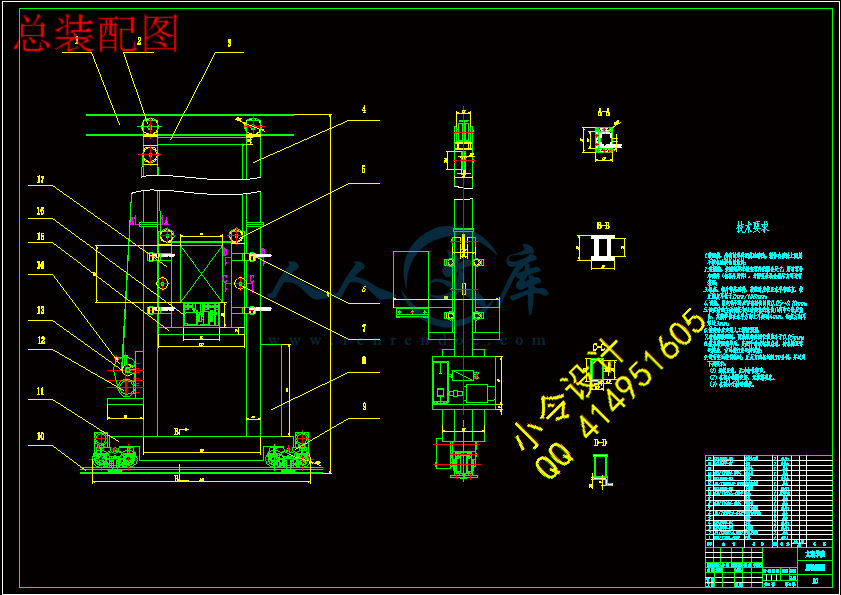
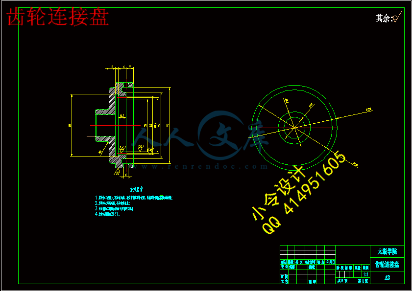
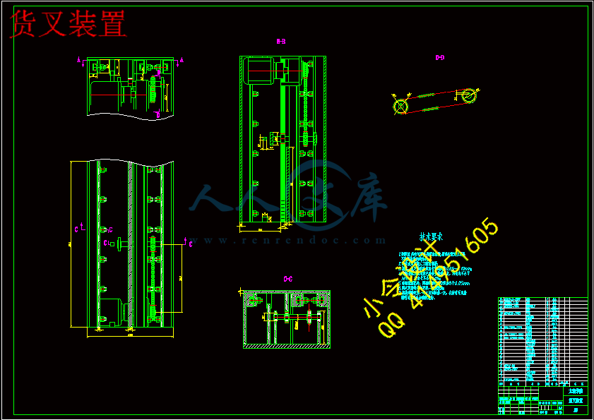
齿轮连接盘.dwg
齿轮连接盘.dwg

自动化立体仓库堆垛起重机机械设计【5张CAD图纸+毕业论文】【答辩通过】

收藏

压缩包内文档预览:
预览图
编号:437779    类型:共享资源    大小:920.48KB    格式:RAR    上传时间:2015-05-31 上传人:好资料QQ****51605 IP属地:江苏
45
积分
关 键 词:
自动化 立体仓库 堆垛 起重机 机械设计
资源描述:

摘  要


近年来,随着企业生产与管理的不断提高,越来越多的企业认识到物流系统的改善与合理性对企业的发展非常重要。堆垛机是自动化立体仓库中最重要的起重堆垛设备,它能够在自动化立体的巷道中来回穿梭运行,将位于巷道口的货物存入货格;或者相反取出货格内的货物运送到巷道口。

本文详细论述了在现代大多数企业中普遍使用的双立柱堆垛机的设计方案,文章的重点放在其两个部件:升降机构、货叉伸缩机构的设计上,并对安全机构和控制部分进行简单的选取和计算其中包含电机,减速器的选取,齿轮,齿条的计算,卷筒的计算,轴的校核,电器原理图的配置等。首先,提出各个机构的总体设计方案;其次,对各个机构的受力情况进行了分析并计算,然后估算初取值,再进行校核,最后确定各个实际值。


关键词:自动化立体仓库;堆垛机;升降机构;货叉伸缩机构


Abstract

   In recent years, along with the unceasing raising of enterprise production and management, more and more enterprises know that thing flows out reasonability and the improvement of system, is very important for the development of enterprise. Stacker cranes is automation three-dimensional storehouse in most important take heavy crane pile up equipment, it can in the tunnel of automation cube in the shuttle operation of round trip, will locate in tunnel the goods of mouth stock goods shelf; or opposite take out the goods transit in goods shelf go to tunnel mouth.

   This paper describes the majority of enterprises in the widespread use of modern double-column stacking machine design, the article focused on its two components: lifting mechanism, telescopic fork design of institutions, and security agencies and the control part simple selection and calculation including motor, reducer selection, gear, rack of calculation, the calculation of roll, axis calibration, electrical schematic diagram of the configuration. First, the proposed design programs of various agencies; Secondly, the force of the various agencies to conduct the analysis and calculation, and then estimate the initial value, and then checked, and finally establish the actual value.


Keyword:automation three-dimensional storehouse;stacker cranes;lifting mechanism; telescopic fork institutions


目  录

摘  要.......................................................................................................................................... III                  

ABSTRACT................................................................................................................................. IV                                                                

目  录........................................................................................................................................... V                                                                              

1 绪论............................................................................................................................................ 1                                                                                

 1.1 研究的背景与内容............................................................................................................................. 1

   1.1.1 概述............................................................................................................................... 1                                                                        

   1.1.2 有轨巷道堆垛机的发展现状及特点........................................................................... 1

   1.1.3 有轨巷道堆垛机的类型............................................................................................... 2

   1.1.4 巷道堆垛机的特点....................................................................................................... 5

 1.2 设计的目的和意义.............................................................................................................. 5

 1.3 设计的内容及要求.............................................................................................................. 5

 1.4 设计参数.............................................................................................................................. 6

 2.1 堆垛机三维运动速度的确定............................................................................................. 7

 2.2 堆垛机各个部分的方案选择.............................................................................................. 8

   2.2.1 堆垛机起升机构传动方式的选择........................................................................................... 8

   2.2.2 堆垛机行走机构传动方式的选择............................................................................... 9

   2.2.3 堆垛机机架的设计思路............................................................................................... 9

   2.2.4 堆垛机货叉的设计思路............................................................................................... 9

   2.2.5 堆垛机安全方案的确定............................................................................................. 11

 2.3 堆垛机的技术参数............................................................................................................ 11

 2.4 堆垛机的技术要求............................................................................................................ 11

3 堆垛机起升机构的设计.......................................................................................................... 15

 3.1 起升机构的总体选型........................................................................................................ 15

 3.2 卷筒的设计........................................................................................................................ 18

   3.2.1 卷筒部件计算............................................................................................................. 18

   3.2.2 齿轮连接盘的计算..................................................................................................... 22

4 堆垛机行走机构和机架的选型设计...................................................................................... 25

 4.1 堆垛机行走机构的选型设计........................................................................................... 25

 4.2 堆垛机机架的选型设计................................................................................................... 27

5 堆垛机货叉的设计.................................................................................................................. 28

 5.1 货叉传动装置的总体选型................................................................................................28

 5.2 货叉传动齿轮、齿条的计算............................................................................................28

 5.3 货叉传动链轮、链条的设计计算....................................................................................32

 5.4 制动器的制动容量的设计................................................................................................34

6 堆垛机安全装置.......................................................................................................................35


 6.1 防撞保护装置.................................................................................................................... 35

 6.2 钢丝绳断绳保护装置........................................................................................................ 35

7 结论与展望.............................................................................................................................. 36

 7.1 结论................................................................................................................................... 36

7.2 不足之处及未来展望........................................................................................................... 36

致  谢.......................................................................................................................................... 37

参考文献...................................................................................................................................... 38


1绪论

1.1 研究的背景与内容

 1.1.1 概述

自动化立体仓库是实现物流系统合理化的关键。它具有空间利用率高、便于实现自动化管理、实时自动结算库存货物种类和数量、立体仓库信息库可以和中央计算机系统联网运行等许多优点,对加快物流速度、提高劳动生产率、降低生产成本都有重要意义,已开始应用于汽车、电子、医药、烟草、建材、邮电等许多行业。而堆垛机对立体仓库的出人库效率有重要影响,是立体仓库能否达到设计要求和体现其优点的关键设备之一。

有轨巷道堆垛起重机是随着立体仓库的出现而发展起来的专用起重机,是在高层货架的窄巷道内作业的起重机,通常简称为堆垛机。堆垛机是立体仓库中最重要的起重运输设备,可大大提高仓库的面积和空间利用率,是自动化仓库的主要设备,是代表立体仓库特征的标志。堆垛机的功能是堆垛机接受计算机指令后,能在高层货架巷道中来回穿梭,把货物从巷道口出人库货台搬运到指定的货位中,或者把需要的货物从仓库中搬运到巷道口出人库货台,再配以相应的转运、输送设备通过计算机控制实现货物的自动出人库。在立体仓库中的搬运设备有高位叉车、工业机器人、桥式堆垛机和有轨巷道式单双立柱堆垛机。有轨巷道式双立柱堆垛机由于效率高,高度可达30-40 m,便于实现无人操作,行走稳定,载货量大,噪声小,在目前的立体仓库中得到广泛应用。


 1.1.2 有轨巷道堆垛机的发展现状及特点

随着经济全球化步伐的口益加快和信息技术的快速发展,传统行业和消费方式正发生着深刻的变化,物流在经济活动中的作用越来越受到企业的重视,物流人才的需求也在口益增长。目前,物流人才已经被列为我国12大类紧缺人才之一,有报道称“物流人才的需求已超过600万”。物流实验室的建设正是要搭建一座理论与实践的桥梁,目前,我国许多高校已经建立了物流实验室,据不完全统计,已经有160多所高校建立了自己的物流实验室。物流实验室为学生提供实训平台,深化学生对现代物流理论的理解,提高学生的操作能力,内融机械、电气、电子及计算机等技术于一体的综合技术,在这种技术中,不同领域和层次的知识与能力融会在一起。

另外,为了更好的模拟货物在自动化立体仓库各仓储单元内存储的物流过程,研究提高物流效率以及堆垛机性能和作业效率方法,许多物流研究中心业纷纷建立起来。山东大学现代物流控制实验中心是目前我国第一个现代的物流控制实验室,在物流调度、物流控制、机械手拣选控制和机器视觉的综合研究和开发应用方面目前处于国内领先地位。


图1.1仓储


1.1.3 有轨巷道堆垛机的类型

有轨巷道堆垛机可按其结构形式、支承方式和运行轨迹等进行分类,一般可分为以下几种类型:

(1) 按结构形式,分为双立柱有轨巷道堆垛机和单立柱有轨巷道堆垛机:

①双立柱有轨巷道堆垛机

双立柱有轨巷道堆垛机由两根立柱、上横梁、下横梁和带货叉的载货台组成,立柱、上横梁和下横梁组成一个长方形的框架,一般称为机架。立柱形式有方管和圆管两种,方管可兼作起升导轨,圆管需要附加起升导轨。这种堆垛机的最大优点就是强度和刚性都比较好,能快速起、制动,并且运行平稳。一般用在起升高度较高、起重量较大和水平运行速度较高的立体仓库中,其缺点是自重较大。其结构如图1.2所示。


图1.2双立柱有轨巷道堆垛机


②单立柱有轨巷道堆垛机

单立柱有轨巷道堆垛机的机架由一根立柱、下横梁和上横梁组成。立柱多采用型钢或焊接制作,立柱上附加导轨。整机重量较轻,消耗材料少,因此制造成本相对较低,但刚性稍差。由于载货台和货物对立柱有偏心作用,以及行走、制动时产生的水平惯性力作用,使单立柱有轨巷道堆垛机在使用上有较大的局限性。不适于起重量大和水平运行速度高的堆垛机。单立柱堆垛机的起升结构,普遍采用钢丝绳传动,由电机减速机驱动卷筒转动,通过钢丝绳牵引载货台沿立柱或起升导轨作升降运动。对于钢丝绳传动,传动和布置相对容易,但定位准确性稍差。其结构如图1.3所示。


图1.3单立柱有轨巷道堆垛机


(2) 按支承方式分类,有轨巷道堆垛机分为悬挂型和地面支承型。

①悬挂型有轨巷道堆垛机

悬挂型有轨巷道堆垛机悬挂在巷道上方的轨道上运行,其运行机构安装在堆垛机门架的上部。在地面铺设导轨,使门架下部的导向轮以一定的间隙夹在导轨的两侧,从而防止堆垛机运行时产生摆动和倾刹。悬挂式堆垛机有如下优点:在设计门架时,可以不考虑横向的弯曲强度,钢结构的自重可以减轻,加减速时的惯性摆动小,稳定所需的时间短;其缺点是维修和检查不方便。

②地面支承型有轨巷道堆垛机

堆垛机的运行轨道铺设在地面上,堆垛机用下部行走轮支承和驱动,上部导向轮用来防止堆垛机倾倒或摆动。和悬挂型有轨巷道堆垛机相比,这种堆垛机的立柱主要考虑轨道平面内的弯曲强度,因此,需要加大立柱在行走方向截面的惯性矩。由于驱动装置均装在

下横梁上,容易保养和维修。

(3) 按其运行轨迹形式不同,分为直线运行型堆垛机和曲线运行型堆垛机。

①直线运行型堆垛机

直线运行型堆垛机只能在巷道内直线轨道上运行,不能自行转换巷道。只能通过其他输送设备转换巷道,直线运行型堆垛机可以实现高速运行,能够满足出入库频率较高的立体仓库作业,应用最为广泛。

②曲线运行型堆垛机

曲线运行型堆垛机行走轮与下横梁是通过垂直轴铰接的,能够在环形或其他曲线轨道上运行,不通过其他输送设备便可以从一个巷道自行转移到另一个巷道。曲线运行型堆垛机在使用上有局限性,只适用于出入库频率较低的立体仓库。

本文研究的堆垛机是结构形式为双立柱,支承方式为地面支承型,并且其运行轨迹为直线型巷道堆垛机。

 1.1.4 巷道堆垛机的特点

   由于使用场合的限制,巷道堆垛机在结构和性能方面有以下特点:

   (1)整机结构高而窄,其宽度一般不超过储料单元的宽度,因此限制了整机布置和结构选型。

   (2)金属结构件除应满足强度和刚度要求外,还要有较高的制造和安装精度。

   (3)采用专门的取料装置,常用多节伸缩货叉或货板机构。

   (4)各电气传动机构应同时满足快速、平稳和准确。

   (5)配备可靠的安全装置,控制系统应具有一系列连锁保护措。

1.2 设计的目的和意义

仓储自动化建设是一项系统工程,物资储运作业自动化是其重要的内容。实现仓库物资储运作业自动化,仓储机械设备、设施及管理、信息、人才系统配套、协调发展是重要的发展趋势。

通过引入计算机、自动控制技术和人工智能等高新技术对仓储机械的技术该做,仓储机械的技术性能将较大提高。载重量大、机动性强、操作方便、可维修性好的叉车、无人叉车、牵引车、托盘运输车、堆高车、堆垛机、码垛机、管道输送机、带状输送机、自动拣选机等先进的装卸搬运机械设备将广泛应用于仓储系统。

本设计通过设计用于仓储货架的堆垛机,完成堆垛机水平行走机构、起升机构、载货台及货叉机构、机架和电气设备的设计,能及时、准确地把物品自动送到指定位置,从而加深对堆垛机的认识与了解。

1.3 设计的内容及要求

   有轨巷道堆垛机的内容包括:

   第一,分析、论述目前堆垛机堆垛的原理、方法,堆垛机的设计思路,探讨各种解决途径。


   第二,论述本设计采用的方法、原理及可行性,进行结构设计、运动学计算和强度计算。

   第三,堆垛机的工作方式及货物识别控制原理。

   第四,绘制堆垛机总装图和主要零部件图。

   有轨巷道堆垛起重机的设计要求包括:

   1.结构简单、操作方便。

   2.堆垛方式准确可靠。

   3.结构紧凑坚固,使用维护方便,外形美观。

1.4 设计参数

   立体仓库为8巷道16排40列7层

堆垛机总高度:8m  总长度:3.1m  总宽度:1m

堆垛机额定起重量300kg

行走最大速度130m/min(2.2m/s)

升降最大速度30m/min(0.5m/s)

货叉速度9m/min(0.15m/s)

加减速度:升降0.6  行走0.6  伸缩0.2

货架上下7层,层高1100mm

货架每层40格,格宽900mm

货箱尺寸:长×宽×高=600×500×800mm

货格尺寸:长×宽×高=900×600×1100mm

宽度方向为货叉叉取方向。


内容简介:
编号无锡太湖学院毕业设计(论文)相关资料题目: FMS自动化立体仓库 堆垛起重机机械结构设计 信机 系 机械工程及自动化专业学 号: 09230102 学生姓名: 赵 磊 指导教师: 尤丽华 (职称:副教授 ) 2013年5月25日目 录一、毕业设计(论文)开题报告二、毕业设计(论文)外文资料翻译及原文三、学生“毕业论文(论文)计划、进度、检查及落实表”四、实习鉴定表无锡太湖学院毕业设计(论文)开题报告题目: FMS自动化立体仓库 堆垛起重机机械结构设计 信机 系 数 控 专业学 号: 00923102 学生姓名: 赵 磊 指导教师: 尤丽华 (职称:教授 ) 2012年11月28日 课题来源本课题来源于工程生产实际,应教学要求,使我们在学习期间接触到一些先进的技术装备和控制技术等重要知识,配合有关课程开设“柔性制造系统综合实验”的需求,培养独立进行科学研究、综合分析思考以及实际动手的能力,此毕业设计由此设立。科学依据目前自动化仓库在发达国家已相当普遍,日本是自动化仓库发展最快,建造数量最多的国家,此外美国、德国、瑞士、意大利、英国、和法国等国家也建造了许多自动化仓库,发展至今,自动化仓库在设计、制造自动化控制盒计算机管理方面的技术也日趋成熟。50年代初,美国美国出现了采用桥式堆垛起重机的立体仓库。60年代初,出现了司机操作的香道式堆垛起重机立体仓库。1963年美国率先在立体仓库中采用计算机控制技术,建立了世界上第一座计算机控制的立体仓库。进入80年代,我国对老式仓库进行技术改造,开始采用自动化立体仓库。1980年由北京机械工业自动化研究所等单位研制建成我国第一座自动化立体仓库,在北京汽车制造厂投产。据不完全统计,目前我国已建成立体仓库已有300座左右,其中全自动的立体仓库有50多座,其中高度在12米以上的大型立体仓库有8座,主要集中在传统优势行业。在此基础上我国对仓库的研究也向着智能化的方向发展,但是目前还处于自动化仓储的推广和应用阶段。研究内容 1.完成FMS自动化立体仓库堆垛起重机机械结构设计的总体设计; 2.完成机架、行走机构、提升机构和载货台、货叉等关键部件设计; 3.绘制相应的二维总装图及主要零部件图纸; 4.设计工作量要求:至少完成A0图纸2张和一份40页以上的毕业论文; 5.查阅相关外文资料并完成不少于8000字符的外文资料翻译; 6.完成一份毕业设计实习报告。拟采取的研究方法、技术路线、实验方案及可行性分析本文从实际问题出发,以现有设备为依托,先确定出堆垛机的总体结构及各部分的结构草图,然后运用理论力学、材料力学、机械设计、制造技术等专业知识,并查阅相关设计手册,对其机械部分进行了详细的设计计算,包括:机架、行走机构、提升机构、载货台和货叉伸缩机构等。设计过程中,以实现堆垛机的机械性能为目的,在满足其强度、刚度、运行稳定性等要求的前提下,综合考虑结构的合理性和所选材料的经济性,力求达到高质量、低成本。可行性分析:由此可见,该设计方案切实可行。研究计划及预期成果研究计划:大致分为如下几个阶段。第一阶段,熟悉老师提供的设计资料,设计参数等,仔细阅读任务书,理清设计思路,搜集资料了解研究目标,构思设计方案。第二阶段,进行方案实施,根据设计参数进行计算,按设计要求进行设计使之满足生产实际,完成设计。第三阶段,制定检测方案及检测方法从而进行校核,改善不满足要求的设计,最后完成图纸。预期成果: 巷道堆垛起重机满足所给自动化立体仓库中各项要求,如:在规定货架上自由提取,存放货物以及完成与输送系统的配合,速度控制严格满足稳定性的要求等。实现最优化设计。特色或创新之处国内外其它行业采用自动化仓库的情况已经充分证明,使用自动化立体仓库能够产生巨大的社会效益和经济效益。这些效益主要表现在以下几个方面: 1.搞层货架存储 由于使用高层货架,存储区可以大幅度地向空间发展,充分利用仓库地面和空间,因此节省了库存占地面积,提高了空间利用率。 2.自动存取 自动化立体仓库使用机械和自动化设备,运行和处理速度快,提高了作业效率。 3.计算机控制与管理 计算机能够准确无误地对仓库的各种信息进行存储和管理,降低了操作人员的劳动强度,从而提高仓库的管理水平。 4.作业效率明显提高 能充分保证“先进先出”的合理作业原则。由于计算机管理、自动作业,可以方便地实施货位和账目的科学管理,改善库存结构,避免盲目压货,并改善劳动环境。 5.节约费用 随着经济的高速的发展,我国有关行业开始重视立体库的研究,对于促进传统观念的转变、提高现代化物流意识,形成新型的商品流通产业等方面均产生了强劲的推动作用。已具备的条件和尚需解决的问题已具备的条件:设计过程中所需要的几种软件、相关搜集资料的网站。尚需解决的问题:相关文献资料的缺乏,对一些结构设计部分的具体设计指导,以及三维软件的高级运用技巧。指导教师意见指导教师(签名): 年 月 日系主任(签名): 年 月 日英文原文:Realization of Neural Network Inverse System with PLC in Variable Frequency Speed-Regulating System Abstract. The variable frequency speed-regulating system which consists of an induction motor and a general inverter, and controlled by PLC is widely used in industrial field. .However, for the multivariable, nonlinear and strongly coupled induction motor, the control performance is not good enough to meet the needs of speed-regulating. The mathematic model of the variable frequency speed-regulating system in vector control mode is presented and its reversibility has been proved. By constructing a neural network inverse system and combining it with the variable frequency speed-regulating system, a pseudo-linear system is completed, and then a linear close-loop is designed to get high performance. Using PLC, a neural network inverse system can be realized in system. The results of experiments have shown that the performances of variable frequency speed-regulating system can be improved greatly and the practicability of neural network inverse control was testified.1.Introduction In recent years, with power electronic technology, microelectronic technology and modern control theory infiltrating into AC electric driving system, inverters have been widely used in speed-regulating of AC motor. The variable frequency speed-regulating system which consists of an induction motor and a general inverter is used to take the place of DC speed-regulating system. Because of terrible environment and severe disturbance in industrial field, the choice of controller is an important problem. In reference 123, Neural network inverse control was realized by using industrial control computer and several data acquisition cards. The advantages of industrial control computer are high computation speed, great memory capacity and good compatibility with other software etc. But industrial control computer also has some disadvantages in industrial application such as instability and fallibility and worse communication ability. PLC control system is special designed for industrial environment application, and its stability and reliability are good. PLC control system can be easily integrated into field bus control system with the high ability of communication configuration, so it is wildly used in recent years, and deeply welcomed. Since the system composed of normal inverter and induction motor is a complicated nonlinear system, traditional PID control strategy could not meet the requirement for further control. Therefore, how to enhance control performance of this system is very urgent.The neural network inverse system 45 is a novel control method in recent years. The basic idea is that: for a given system, an inverse system of the original system is created by a dynamic neural network, and the combination system of inverse and object is transformed into a kind of decoupling standardized system with linear relationship. Subsequently, a linear close-loop regulator can be designed to achieve high control performance. The advantage of this method is easily to be realized in engineering. The linearization and decoupling control of normal system can realize using this method.Combining the neural network inverse into PLC can easily make up the insufficiency of solving the problems of nonlinear and coupling in PLC control system. This combination can promote the application of neural network inverse into practice to achieve its full economic .In this paper, firstly the neural network inverse system method is introduced, and mathematic model of the variable frequency speed-regulating system in vector control mode is presented. Then a reversible analysis of the system is performed, and the methods and steps are given in constructing NN-inverse system with PLC control system. Finally, the method is verified in traditional PI control and NN-inverse control.2.Neural Network Inverse System Control MethodThe basic idea of inverse control method 6 is that: for a given system, an-th integral inverse system of the original system is created by feedback method, and combining the inverse system with original system, a kind of decoupling standardized system with linear relationship is obtained, which is named as a pseudo linear system as shown in Fig.1. Subsequently, a linear close-loop regulator will be designed to achieve high control performance.Inverse system control method with the features of direct, simple and easy to understand does not like differential geometry method 7, which is discusses the problems in geometry domain. The main problem is the acquisition of the inverse model in the applications. Since non-linear system is a complex system, and desired strict inverse is very difficult toobtain, even impossible. The engineering application of inverse system control dont meet the expectations. As neural network has non-linear approximate ability, especially for nonlinear the powerful tool to solve the problem.a th NN inverse system integrated inverse system with non-linear ability of the neural network can avoid the troubles of inverse system method. Then it is possible to apply inverse control method to a complicated non-linear system. a th NN inverse system method needs less system information such as the relative order of system, and it is easy to obtain the inverse model by neural network training. Cascading the NN inverse system with the original system, a pseudo-linear system is completed. Subsequently, a linear close-loop regulator will be designed.3. Mathematic Model of Induction Motor Variable FrequencySpeed-Regulating System and Its ReversibilityInduction motor variable frequency speed-regulating system supplied by the inverter of tracking current SPWM can be expressed by 5th order nonlinear model in d-q two-phase rotating coordinate. The model was simplified as a 3-order nonlinear model. If the delay of inverter is neglected, the model is expressed as follows: (1)where denotes synchronous angle frequency, and is rotate speed. are stators current, and are rotors flux linkage in(d,q)axis. is number of poles. is mutual inductance, and is rotors inductance. J is moment of inertia.is rotors time constant, and is load torque.In vector mode, thenSubstituted it into formula (1), then (2)Taking reversibility analyses of forum (2), thenThe state variables are chosen as followsInput variables areTaking the derivative on output in formula(4), then (5) (6)Then the Jacobi matrix is Realization of Neural Network Inverse System with PLC (7) (8)As so and system is reversible. Relative-order of system is When the inverter is running in vector mode, the variability of flux linkage can be neglected (considering the flux linkage to be invariableness and equal to the rating). The original system was simplified as an input and an output system concluded by forum (2).According to implicit function ontology theorem, inverse system of formula (3)can be expressed as (9)When the inverse system is connected to the original system in series, the pseudo linear compound system can be built as the type of 4. Realization Steps of Neural Network Inverse System4.1 Acquisition of the Input and Output Training Samples Training samples are extremely important in the reconstruction of neural network inverse system. It is not only need to obtain the dynamic data of the original system, but also need to obtain the static date. Reference signal should include all the work region of original system, which can be ensure the approximate ability. Firstly the step of actuating signal is given corresponding every 10 HZ form 0HZ to 50HZ, and the responses of open loop are obtain. Secondly a random tangle signal is input, which is a random signal cascading on the step of actuating signal every 10 seconds, and the close loop responses is obtained. Based on these inputs, 1600 groups training samples are gotten.4.2 The Construction of Neural Network A static neural network and a dynamic neural network composed of integral is used to construct the inverse system. The structure of static neural network is 2 neurons in input layer, 3 neurons in output layer, and 12 neurons in hidden layer. The excitation function of hidden neuron is monotonic smooth hyperbolic tangent function. The output layer is composed of neuron with linear threshold excitation function. The training datum are the corresponding speed of open-loop, close-loop, first orderderivative of these speed, and setting reference speed. After 50 times training, the training error of neural network achieves to 0.001. The weight and threshold of the neural network are saved. The inverse model of original system is obtained.5 .Experiments and Results5.1 Hardware of the System The hardware of the experiment system is shown in Fig 5. The hardware system includes upper computer installed with Supervisory & Control configuration software WinCC6.0 8, and S7-300 PLC of SIEMENS, inverter, induction motor and photoelectric coder.PLC controller chooses S7-315-2DP, which has a PROFIBUS-DP interface and a MPI is connected with S7-300 by CP5611 using MPI protocol.The type of inverter is MMV of SIEMENS. It can communicate with SIEMENS PLC by inverter in this system.5.2 Software Program5.2.1 Communication IntroductionMPI (Mu Point Interface) is a simple and inexpensive communication strategy using in slowly and non-large data transforming field. The data transforming between and PLC is not large, chosen. The MMV inverter is connected to the PROFIBUS network as a slave station, which is mounted with CB15 PROFIBUS module. PPO1 or PPO3 data type can be chosen. It permits to send the control data directly to the inverter addresses, or to use the system function blocks of SFC14/15.OPC can efficiently provide data integral and intercommunication. Different type servers and clients can access data sources of each other. Comparing with the traditional mode of software and hardware development, equipment manufacturers only need to develop one driver. This can short the development cycle, save manpower resources, and simplify the structure of the entire control system. Variety data of the system is needed in the neural network training of , which can not obtain by reading from PLC or directly. So OPC technology can be used l to obtain the needed data between . Setting as OPC DA server, an OPC client is constructed in Excel by VBA. System real time data is and to Excel by, and then the data in Excel is transform to for offline training to get the inverse system of original system.5.2.2 Control Program Used STL to program the communication and data acquisition and control algorithm subroutine in STEP7 V5.2, velocity sample subroutine and storage subroutine are programmed in regularly interrupt A, and the interrupt cycle chooses 100ms. In order to minimum the cycle time of A to prevent the run time of A exceeding 100ms and system error, the control procedure and procedure B. In neural network algorithm normalized the training samples is need to speed up the rate of n input and output data before the final training. 5.3 Experiment ResultsWhen speed reference is square wave signal with 100 seconds cycle, where the inverter is tracking performance of neural network control is better than traditional PI control. When speed reference keeps in constant, and the load is reduced to no load at 80 seconds, and increased to full load at 120 seconds, the response curves of speed with traditional PI control and neural network inverse control are shown in Fig. 11 and 12 respectively. It is clearly that the performance of resisting the load disturbing with neural network inverse control is better than the traditional PI control. (Speed response in PI control) (Speed response in neural network inverse control)6. Conclusion In order to improve the control performance of PLC Variable Frequency Speed-regulating System, neural network inverse system is used. A mathematic model of variable frequency speed-regulating system was given, and its reversibility was testified. The inverse system and original system is compound to construct the pseudo linear system and linear control method is design to control. With experiment, neural network inverse system with PLC has its effectiveness and its feasibility in industry application.中文译文PLC变频调速的网络反馈系统的实现 摘要。变频调速系统,包括一个异步电动机和通用逆变器、且PLC控制被广泛地应用于工业领域。然而,对多变量、非线性和强耦合的异步电机的控制性能却不足,不能很好地满足客户的调速要求。该数学模型的变频调速系统提出了矢量控制方式,其可逆转性得到证实。通过构建一种基于神经网络的逆系统,并结合变频调速系统,pseudo-linear系统被完成了,并且为了得到性能优良的系统采用了一个线性闭环调节器。采用PLC、神经网络逆系统在实际系统可以实现。实验结果表明变频调速系统的性能得到了很大的提高,并且神经网络反馈控制的可行性得到了验证。1. 导论近年来,随着电力电子技术、微电子技术和现代控制理论,逐渐涉及到交流电机系统,这些技术已经广泛应用于变频器调速的AC马达。变频调速系统,包括一个异步电动机和通用逆变器,用来代替直流调速系统。由于在工业领域中的糟糕的环境和严重的干扰,选择控制器是一个十分重要的问题。在文献123,介绍了利用工业控制计算机和数据采集卡实现了神经网络反馈控制。工业控制计算机的优势有较高的计算速度,庞大的记忆能力以及与其他软件良好的兼容性等。但是工业控制计算机在工业应用上也有一些不足,比如运行不稳定,不可靠及更恶劣的通信能力。可编程序控制器(PLC)控制系统是专为工业环境中的应用而设计的,它的稳定性和可靠性好。PLC控制系统,可以很容易地集成到现场总线控制系统并得到高性能的通信结构,所以它在近年来被广泛地使用,并且深受欢迎。该系统由普通的逆变器和异步电机组成,是一种复杂的非线性系统,传统的PID控制策略,并不能满足要求和进一步控制。因此,如何加强系统的控制性能是非常迫切的事情。神经网络逆系统45, 在未来几年里将是一种新型的控制方法。其基本的想法是:对于一个给定的系统,原系统的逆系统是由一个动态神经网络引起的,对象信号和反馈信号的组合系统被转化成一种线性关系的解耦标准系统。随后,一个线性闭环调节器设计可以达到较高的控制性能。该方法的优点是在工程上很容易实现。在线性化及其解耦控制正常的非线性系统能实现采用这种方法。把神经网络反馈结合到可编程序控制器(PLC)上就可以很容易地弥补不足的问题,解决在PLC控制系统上的非线性耦合。这个组合可以促进神经网络反馈付诸实践,来实现其全部的经济效益和社会效益。在这篇文章中,首先对神经网络反馈方法进行了介绍,并且描述了采用矢量控制的变频调速系统的数学模型。然后是对反馈系统进行分析的的介绍,并给出了关于PLC控制系统中构造NN-反馈系统的方法和步骤。最后,该方法在实验中被验证,并将传统的PI控制和NN-反馈控制进行了对比。2. 神经反馈网络控制方法基本的反馈控制方法6就是:对于一个给定的系统、一种-th由反馈方法建立的完整的反馈系统,并结合反馈系统与原系统的特点,提出了一种解耦的线性关系,以标准化体系,并命名为伪线性系统。随后,一个线性闭环调节器运行并将达到较高的控制性能。当在“几何领域”讨论这些问题时,反馈系统控制方法并不像微分几何方法,其特点是直接,简单,易于理解。主要的问题是怎样在应用软件中获得反馈模型。由于非线性系统是一个复杂的系统,所以很难要求严格解析反馈信号,这甚至是不可能的。反馈系统控制在工程应用中不能达到期望值。作为神经网络非线性逼近能力,尤其是对于非线性的复杂系统,它会是来解决问题的强大工具。反馈系统集成了具有非线性逼近能力的反馈系统,其中具有非线性逼近能力的反馈系统能够避免使用反馈方法带来的麻烦。这样就可能,运用反馈控制方法去控制一个复杂的非线性系统。a th NN 反馈系统的控制方法只需要较少的系统信息,比如与系统相关的命令,并且容易获得运行网络的反馈模型。原系统的层叠式的 NN反馈系统,会形成一个伪线性系统。然后,一个线性闭环调节校准器将工作。3. 异步电机变频调速系统的数学模型和它的反馈性能异步电机变频调速系统提供的跟踪电流正弦脉宽调制逆变器可以表示为非线性模型在两相循环的协调。该模型简化为一个3-order非线性模型。如果忽略逆变器的延迟,该模型表述如下: (1) (表示同步角频率;表示转速;表示定子的电流;表示转子在(qd)轴线上的不稳定部分;表示点的数量;表示互感系数;表示惯性转矩;表示转子的时间常数;表示负载转矩。)用矢量模式,得代进公式(1),得 (2)可逆转性分析(2),得 (3) (4)可供选择的状态变量如下输入变量由公式(4)得出结果,得 (5) (6)然后雅可比矩阵 (7) (8)作为 所以并且系统是可逆的。相关
温馨提示:
1: 本站所有资源如无特殊说明,都需要本地电脑安装OFFICE2007和PDF阅读器。图纸软件为CAD,CAXA,PROE,UG,SolidWorks等.压缩文件请下载最新的WinRAR软件解压。
2: 本站的文档不包含任何第三方提供的附件图纸等,如果需要附件,请联系上传者。文件的所有权益归上传用户所有。
3.本站RAR压缩包中若带图纸,网页内容里面会有图纸预览,若没有图纸预览就没有图纸。
4. 未经权益所有人同意不得将文件中的内容挪作商业或盈利用途。
5. 人人文库网仅提供信息存储空间,仅对用户上传内容的表现方式做保护处理,对用户上传分享的文档内容本身不做任何修改或编辑,并不能对任何下载内容负责。
6. 下载文件中如有侵权或不适当内容,请与我们联系,我们立即纠正。
7. 本站不保证下载资源的准确性、安全性和完整性, 同时也不承担用户因使用这些下载资源对自己和他人造成任何形式的伤害或损失。
提示  人人文库网所有资源均是用户自行上传分享,仅供网友学习交流,未经上传用户书面授权,请勿作他用。
关于本文
本文标题:自动化立体仓库堆垛起重机机械设计【5张CAD图纸+毕业论文】【答辩通过】
链接地址:https://www.renrendoc.com/p-437779.html

官方联系方式

2:不支持迅雷下载,请使用浏览器下载   
3:不支持QQ浏览器下载,请用其他浏览器   
4:下载后的文档和图纸-无水印   
5:文档经过压缩,下载后原文更清晰   
关于我们 - 网站声明 - 网站地图 - 资源地图 - 友情链接 - 网站客服 - 联系我们

网站客服QQ:2881952447     

copyright@ 2020-2025  renrendoc.com 人人文库版权所有   联系电话:400-852-1180

备案号:蜀ICP备2022000484号-2       经营许可证: 川B2-20220663       公网安备川公网安备: 51019002004831号

本站为文档C2C交易模式,即用户上传的文档直接被用户下载,本站只是中间服务平台,本站所有文档下载所得的收益归上传人(含作者)所有。人人文库网仅提供信息存储空间,仅对用户上传内容的表现方式做保护处理,对上载内容本身不做任何修改或编辑。若文档所含内容侵犯了您的版权或隐私,请立即通知人人文库网,我们立即给予删除!