选题申报表.doc

三通管注塑模具设计【24张CAD图纸+WORD毕业论文】【注塑模具类】

收藏

资源目录
跳过导航链接。
三通管注塑模具设计【CAD图纸+WORD毕业论文】【注塑模具类】.rar
A3222-[M]全套设计-三通管注塑模具设计
[M]全套设计-三通管注塑模具设计
选题申报表.doc---(点击预览)
说明书正文.doc---(点击预览)
说明书摘要.doc---(点击预览)
程序清单.doc---(点击预览)
开题报告.doc---(点击预览)
工艺过程卡片.doc---(点击预览)
实习报告.doc---(点击预览)
任务书.doc---(点击预览)
三维图集.doc---(点击预览)
A4-顶杆.dwg---(点击预览)
A4-限位套.dwg---(点击预览)
A4-锁紧块.dwg---(点击预览)
A4-轴.dwg---(点击预览)
A4-浇口套.dwg---(点击预览)
A4-导柱.dwg---(点击预览)
A4-导套.dwg---(点击预览)
A4-复位杆.dwg---(点击预览)
A3-顶杆固定板.dwg---(点击预览)
A3-顶出底板.dwg---(点击预览)
A3-滑轨.dwg---(点击预览)
A3-滑板2.dwg---(点击预览)
A3-滑板1.dwg---(点击预览)
A3-模脚.dwg---(点击预览)
A3-定位圈.dwg---(点击预览)
A3-型芯.dwg---(点击预览)
A3-凹模2.dwg---(点击预览)
A3-凹模1.dwg---(点击预览)
A3-三通管.dwg---(点击预览)
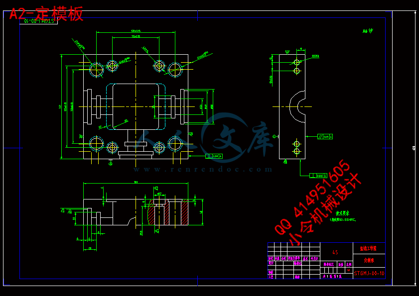
A2-定模板.dwg---(点击预览)
A2-定模底板.dwg---(点击预览)
A2-动模板.dwg---(点击预览)
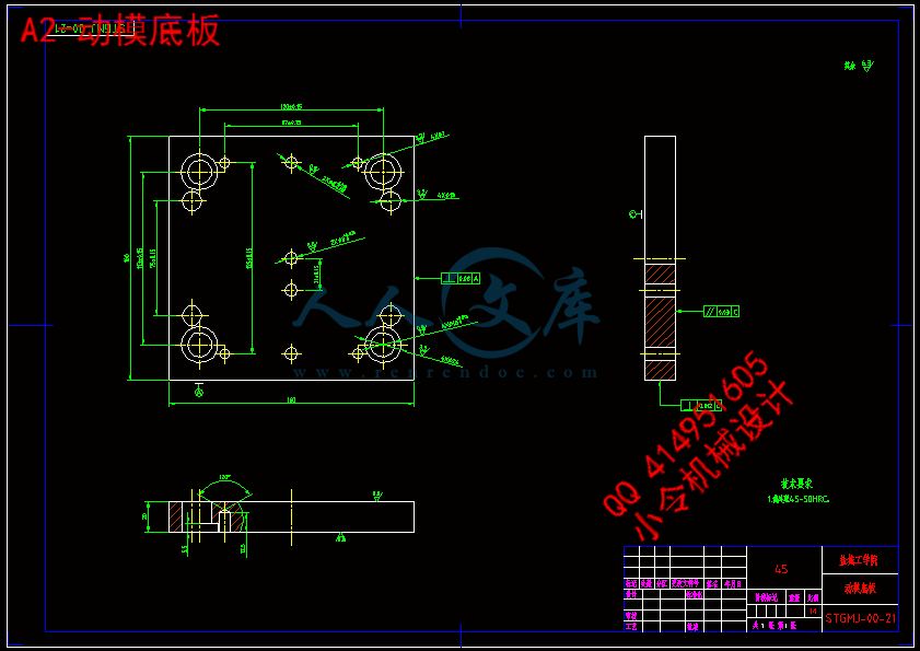
A2-动模底板.dwg---(点击预览)
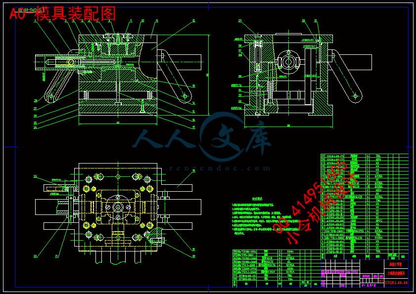
A0-模具装配图.dwg---(点击预览)
外文翻译
文献资料
压缩包内文档预览:
预览图
编号:438277    类型:共享资源    大小:10.44MB    格式:RAR    上传时间:2015-06-02 上传人:好资料QQ****51605 IP属地:江苏
45
积分
关 键 词:
三通 注塑 模具设计 cad 图纸 word 毕业论文 模具
资源描述:

三通管注塑模具设计

摘 要:模具工业是国民经济的基础工业,而塑料模具又是整个模具行业的霸主。本次设计的是聚氯乙烯塑件(三通管),因为该制件三面通孔,故采用的是一模一腔注射,使用双分型面模具,利用侧向抽芯机构去除型芯。注射机的选择应依据制件的质量和体积,并且对注射剂的参数进行校核。该产品采用点浇口注射,并利用间隙排气。型腔是由两镶块构成,利用斜滑轨侧向分型,并通过限位销限制抽芯的距离。该模具通过推杆推出制件,闭合时,同样在导柱和导套的导向作用下通过复位杆的弹簧使复位杆先于型腔复位,以免顶杆碰到型腔,损坏模具。借助三维软件PRO/E进行模具的三维造型,并对模具分析,简化了设计过程,减少了劳动量。本次模具设计合理,符合实际应用,能够生产结构合理、精度高、表面质量好的塑料模具。


关键词:注射模;型腔;型芯;PRO/E


Design of Injection Mold for Tee

Abstract: The mold industry is the national economical foundation,and the plastic mold is also the overlord in the entire mold industry. The design is plastic parts of HPVC. Because the parts have three holes distrabute in three sides, it has one part in one cavity, seperates in two position, takes out the core by side. The selection of injection machine depends on the volume and quality of the parts, then it needs to check whether the injection machine’s parameters is in line with requestions. The mold injects plastic through a gate of point, and push the gas out of the mold from the gap. The cavity is formed with two inserts, and uses Oblique slider to separate the mold, and limites the distance of the pin. The mold pushes the part with the putter. when closes it, the guiding Column and case guide the spring make the reposition pole back to it’s former location, in order to prevent the pole encontered the cavity to hurt the mold.With the help of the software PRO/E, it can make three-dimensional of the mold, to simplify the designing process and reduce manual labor. The design is reasonable, in line with actual application, and it can produce right construction, high precision, well surface quality plastic mold.


Key word: Injection mold; Cavity; Core; PRO/E;


目    录

1 绪论1

2 塑件的工艺分析2

2.1 塑件材料成型工艺分析2

2.2 塑件结构工艺性分析3

2.3 型腔布局及分型面的选择4

3 成型设备的选择6

3.1 估算制件的体积和质量6

3.2 选择注射机6

3.3注射机有关参数的校核6

3.4 模架的选择7

4 注射模的结构设计9

4.1 浇注系统的设计9

4.1.1 主流道的设计9

4.1.2 主流道衬套的固定10

4.1.3分流道的设计10

4.1.4浇口的设计11

4.1.5排气方案的确定11

4.2 成型零部件设计12

4.2.1成型零部件结构设计12

4.2.2成型零件工作尺寸计算13

4.3 导向机构与定位机构的设计16

4.3.1 导柱的结构16

4.3.2 导套的结构17

4.3.3 锁紧块的结构17

4.4 脱模机构的设计18

4.5 侧向抽芯机构的设计19

5 温度调节系统的设计21

6 模具的装配22

6.1  模具的装配顺序22

6.2  开模过程分析22

7 凹模的机械加工仿真23

8 结论28

参考文献29

致  谢30

附    录31


1 绪论

本次设计的题目是三通管的注塑模具设计,课题以社会实际产品为原型,设计一副能够生产所给塑件、结构合理、能保证制品的精度、表面质量的塑料模具。

随着塑料制品在机械、电子、交通、国防、建筑、农业等各行业 广泛应用,对塑料模具的需求日益增加,塑料模在国民经济中的重要性也日益突出。模具作为一种高附加值和技术密集型产品,其技术水平的高低已经成为一个国家制造业水平的重要标志之一。

本设计严格按照模具设计的步骤,及模具设计中的要求来设计的:对塑件工艺性的分析、型腔数量的确定、分型面的确定、注塑机的选择及校核、浇注系统的设计、成型零件的设计等,其次,还要对模具导向机构、脱模机构、抽芯机构进行结构设计,温度调节系统对模具也有重要作用,模具温度直接影响到塑件的质量如收缩率、翘曲变形、耐应力开裂性和表面质量等,并且对生产效率起到决定性的作用。设计中要进行一整套的程序,自己要在各方面的都应了解。在塑料材料、制品设计及加工工艺确定以后,塑料模具设计对制品质量与产量,就决定性的影响。首先,模腔形状、流道尺寸、表面粗糙度、分型面、进浇与排气位置选择、脱模方式以及定型方法的确定等,均对制品(或型材)尺寸精度形状精度以及塑件的物理性能、内应力大小、表观质量与内在质量等,起着十分重要的影响。其次,在塑件加工过程中,塑料模结构的合理性,对操作的难易程度,具有重要的影响。再次,塑料模对塑件成本也有相当大的影响,除简易模外,一般来说制模费用是十分昂贵的,大型塑料模更是如此。加工工艺要求、塑件使用要求、塑件外观要求,起着无可替代的作用。高效全自动化设备,也只有装上能自动化生产的模具,才能发挥其应有的效能。此外,塑件生产与更新均以模具制造和更新为前提。

同时在设计中也要求对机械的相关知识有相当的了解:机械制图、公差与配合、机械制造、材料成型、数控技术等。对模具的仿真过程也是对我们能力的一种培养,设计完成之后,对模具装配的可靠性检查也是模具设计过程中必不可少的。


2 塑件的工艺分析

制品的分析是对所要成型的产品有个初步的了解,在接受设计任务书以后就要对塑料的品种、批量的大小、尺寸精度与技术条件,产品的功用及工作条件有个整体概念,以便在设计模具时优选各种方式来成型塑件。


内容简介:
Visual Feedback Control of a Micro Lathe Hirotaka OJIMA1, Katsuhiro SAITO1, Libo ZHOU1, Jun SHIMIZU1, Hiroshi EDA11Ibaraki UniversityKeywords: Micro lath, Visual feedback, Position controlAbstractMicromachining progresses rapidly in recent years. In this research, a micro lathe which is installable and operationalinside SEM vacuum chamber has been designed anddeveloped. As a first step, visually guided micro lathesystem is developed with image of CCD camera deviceinstead of SEM image. Unlike the conventional feedbackcontrol which positions the X- Y table only, this scheme offers a direct control of the position, path and speed of thetool tip. Using proposed method, cutting experiment wasachieved, and it is confirmed that developed micro lathesystem is effective to do cutting.1 Introduction Recently, the system capable of producing the micro partsare requested along with the miniaturization1.Micromachining progresses rapidly in recent years. Theexploratory research has approached to a level of accessing asingle molecule or atom. As a driving force, MEMS (microelectronic- mechanical system) has been playing a major rolein making micro components and devices. However, MEMS is based on the photolithography technology and therebyapplicable into limited materials such as siliconmonocrystalline. In orderto meet the demands of miniaturization in electronic and optical applications, alternative micromachining technology which is able toaccess a variety of materials in a 3 dimensional way isrequired2.Micro- Meso Mechanical Manufacturing (M4) offersaccessibility to different kinds of material according to eachobjective, and attains high repeatability and accuracy withthe latest ultraprecision means. There are, however, manyscientific and technological barriers encountered inpragmatic implementation of M4. One of them is the surfacechemistry effects. When machining parts are at micro scale,it is recognized that the surface- area- to- volume ratio will beincreased in both chips and the resulting part as compared to conventional (macro) machining process. Another problem is the direct motion and position control. Sensors that arecapable of directly measuring the relative displacementbetween the tool and workpiece are not yet available.In this research, a micro lathe which is installable andoperational inside SEM vacuum chamber has been designedand developed3. Fig. 1 shows the concepts of the developedmicro lathe. At such oxygen- free condition, cutting tests areconducted to understand surface chemistry effects on micromachining. However, since developed micro lathe issmall in size, rigidity of the lathe is low. Thus the position ofthe tool of the lathe is not able to be controlled accuratelywith a conventional method which controls X- Y table only.Therefore, the vision guided control method is proposed.Theimage from the SEM (scanning electronmicroscope) is digitized by CCD into pixels with 8- bit grayscale. Since each pixel contains 2D positional information,the vision system thus offers an orthogonal coordinate(hereafter referred as the pixel coordinate) for objects inview to refer to. The pixel coordinate is free from themechanical inaccuracy and offers a direct measurement ofSEMCCDMicro latheSEMCCDMicro latheFig. 1. Concept of the developed micro lathe ?H. Ojima, K. Saito, L. Zhou, J. Shimizu, H. Edathe relative position of tool and workpiece. The resolutionincreases together with the magnification of the microscopeand the number of CCD pixels. In this research, a visioncontrol scheme has been proposed and implemented forfeedbackcontrol of the tool movements. Unliketheconventional feedback control which positions the X- Y tableonly, this scheme offers a direct control of the position, pathand speed of the tool tip. As a first step, visually guidedmicro lathe system is developed with image of CCD cameradevice instead of SEM image. 2 Overview of system Actuating moduleSensing moduleProcessingmoduleImage information Actuator signalCapture boardMicro latheXZ stageAMPCPUDiamondtoolCCDWorkpieceD/A boardActuating moduleSensing moduleProcessingmoduleImage information Actuator signalCapture boardMicro latheXZ stageAMPAMPCPUCPUDiamondtoolCCDWorkpieceD/A boardFig. 2. Block diagram of systemTable 1. Specification of systemSize of micro lathe(WDH)909042 (mm)Spindle rotational speed0?8000 (rpm) Depth of cut Traverse feed1010 (mm) Center high adjustment30 (?m)ToolDiamondNose angle / nose radius40() / 2 (?m)Scanning rate20 (frame/s) Total pixels0.3 mega pixel Shown in Fig. 2 is the block diagram of developed microlathe system, which consists of three main modules; the actuating module that drives micro lathe, the sensing module that imports images and the processing module that implements feedback control. Each module is responsible fordifferent function. The actuating module is the core element where the cutting operation is carried out. The sensingmodule imports images from CCD image device, and obtainsthe position of the tool and the workpiece. The other tasks including the image processing and feedback control areexecuted by the processing module. Upper picture of Fig. 1shows the overall appearance of the system. Table .1 showsthe specifications of the system.The actuating module further incorporates a diamondtool with a XZ linear stage, and the sensing module includesa high resolution CCD image device. Through sensingmodule, the appearance of the working area is not only displayed on the monitor to the give the operator the visual information, but also converted into digital signal forsubsequent processing. As the control diagram show in Fig. 2, the movements ofthe diamond tool are governed with the visual feedbackcontrol. The sensing module first abstracts the positions ofthe tool and workpiece by comparing the pre- registeredtemplates with the captured visual information.Corresponding to the relative positions of tool and workpiece, the tool path and speed are calculated and converted intoappropriate pulse train.egfhefghacbdabcd? ?egfhefghacbdabcd? ?Fig. 4. Driving principle of XZ- stageXYZCenter highadjustmentDC motorSpindleXZ- stageMicro latheXYZXYZCenter highadjustmentDC motorSpindleXZ- stageMicro latheFig. 3. XZ- stage and micro lathe3 Actuating moduleThe developed micro lathe is shown rightward in Fig. 3. Thislathe consists of the main spindle with the collet chuck withthe DC motor, the centerhigh adjustment using apiezoelectric actuator and XZ- stage which performs both depth of cut (X- axis) and traverse feed (Z- axis). The XZ-stage is driven by the inertial sliding, and is composed of apiezoelectric actuator and the linear guide.XZ- stage is shown leftward in Fig. 3. An accurate toolpositioning is achieved by driving the XZ- stage precisely.Important points of driving the XZ- stage are the control of the driving direction, distance and velocity. Figure 4 shows the inertial sliding mechanism by the saw- tooth wave. Thedirection of the movement is decided by the rising/trailingedge of the saw- tooth wave as shown in Fig. 4. For example, ?Visual Feedback Control of a Micro Lathethe mechanism in the right direction (+) is explained as follows. The voltage gradually rises, and a piezoelectricactuator stretches most in (1). The actuator shrinks based on the centroid in (2) by falling rapidly of the voltage. Only theside where the frictional force is small moves as the actuatorstretches gradually with the ascent of the voltage in (3). Theactuator is stretches again in (4), and advances toward the right direction. The actuator similarly advances also towardthe left direction (- ) if a reverse pulse train is given.00.10.20.30.40200400600Frequency?HzSpeed?mm/s80V40VFig. 5. Velocity change depending on frequency and voltageNext, the velocity control of this mechanism is described.As shown in Fig. 5, the velocity is proportional to bothfrequency of the pulse train and driving voltage.Finally, driving distance can be controlled according tothe number of pulses, because the driving distance by oneplus is about 500?m at 80V or 250?m at 40V. (500,420)(140,420)(500,60)(140,60)XZ(320,240)4123(500,420)(140,420)(500,60)(140,60)XZ(320,240)4123Fig. 8. Experimental condition of linear path controlX pixelZ pixelcount210121011000200300400X pixelZ pixelcount210121011000200300400Fig. 7. Recognition accuracy of tool tip XZ- stageDiamondtoolCCDWork piece(X,Z)ZXXZ- stageDiamondtoolCCDWork pieceXZ- stageDiamondtoolCCDWork piece(X,Z)ZX(X,Z)ZXFig. 6. Visual sensing system4 Sensing module The diamond tool is mounted on XZ- stage, which uses piezoelectric actuator to drive tool. Those mechanicalinaccuracies,mainly caused by thermal expansion,hysteresis/drift in actuators and misalignment of orthogonal axis, may directly deliver a negative effect to the systemperformance. To solve these problems, a vision controlscheme as shown in Fig. 6 is developed. The left picture inFig. 6 shows the micro lathe and CCD image device locatedin Y- axis. From the right picture in Fig. 6, the incomingvisual information from the CCD is digitized into pixels with8- bit gray scale by the sensing module. As each pixel bears 2D positional information, the vision system thus offers anorthogonal coordinate (referred as the pixel coordinate) forobjects in view to refer to. The pixel coordinate is free fromthe mechanical inaccuracy and its resolution increasestogether with the magnification of the CCD. At a 480640 pixel frame used in the current research,for example, the resolution of the pixel coordinate is about6?m when the view of the CCD is twofold magnified. Whenthe CCD is aligned along Y- axis, the position of the tool tipand workpiece is projected into a 2D pixel coordinate (XZ)which is commonly shared by the XZ- stage and workpiece.Driven and controlled by the pixel coordinate, the tool isable to be positioned and moved at the accuracy of pixelresolution with no effect by the mechanical inaccuracy. Inaddition, if the rigidity between XZ- stage and tool is low,positioning of tool tip is not achieved by driving XZ- stage accurately. Thus, more importantly, this operation is aneffective method of positioning for the micro lathe with alow rigidity.Figure 7 shows the recognition accuracy that is made byuse of shape based pattern matching4 to recognize the actualtool tip repeatedly 500 times. We comprehend from thegraph that 88.5% reliability can be achieved within the limesof 1pixel (6?m).5 Processing module For the system which is consisted of the actuating andsensing module in previous section 3 and 4, the visual? H. Ojima, K. Saito, L. Zhou, J. Shimizu, H. Eda feedback control method is described in this section. The tool tip is driven by visual feedback control method with positions of the tool tip and targets from CCD image device. As a first step, we examined linear path control and circular path control of the tool tip. In these path controls, driving frequency is 300Hz (162?m/s). At first, liner path control of tool tip is described. As shown in Fig. 8, the target position is defined as (320, 240) which is the center of the image from CCD, and four kinds of path control are examined. In the case of liner path control, the angle formed by the target position and the present position of the tool tip is fed back to achieve the path control. Figure 9 (a) shows the resultant path of the tool tip without feedback control, and (b) shows that with feedback control. In the case of the path without feedback, final errors of four paths are between 5pixels (30?m) and 15pixels (90?m). On the other hand, the path with feedback follows along the target path, and final error is within 2pixels (12?m).Next, the circular path control which is multi-axial interpolation is described. The condition of the circular path control is shown in Fig. 10. The center of the target circular path is defined as (320, 240) which is the center of the image from CCD, and the radius of the target path is 100pixels (600?m), moreover the tool tip is driven from starting point (220, 240) along counterclockwise direction repeated 3 times. In the case of circular path control, we consider to feed back not only the angle formed the center of the target circular path and the present tool position, but also the deviation of the radius which is the error between the radius of the target circular path and the distance from the center of the target path to the present tool position. In the case of the driving the path without feedback control, the tool is driven by the angles prepared in advance. Figure 11 (a) shows the resultant path of the tool tip without feedback control, and (b) shows the path with feedback control of the angle only, and (c) shows the path with feedback control of the angle and radius. Figure 11 (a) shows that the resultant path departed from target path, and the center and the radius of the path are deflected from those of the target path. Figure 11 (b) shows the center of the resultant path matches the center of the target path, but extends the radius of the resultant path as the path goes around. Moreover, Fig. 11 (c) shows that the resultant path 0100200300400500100 200 300 400 500 600X pixelZ pixelgoal12340100200300400500100 200 300 400 500 600X pixelZ pixelgoal1234 (a) without feedback control 0100200300400500100 200 300 400 500 600X pixelZ pixelgoal12340100200300400500100 200 300 400 500 600X pixelZ pixelgoal1234 (b) with feedback control Fig. 9. Experimental results of linear path control (220,240)(320,240)XZCCW(220,240)(320,240)XZCCWFig. 10. Experimental condition of circular path control 0100200300400100200300400500X pixelZ pixel0100200300400100 200 300 400 500X pixelZ pixel0100200300400100200300400500X pixelZ pixeltooltarget tooltarget tooltarget 0100200300400100200300400500X pixelZ pixel0100200300400100 200 300 400 500X pixelZ pixel0100200300400100200300400500X pixelZ pixeltooltarget tooltarget tooltarget tooltarget tooltarget tooltarget (a) without feedback control? (b) with feedback control of the angle (c) with feedback control of the angle and radius Fig. 11. Experimental results of circular path control ?Visual Feedback Control of a Micro Lathefollows the target circular path closely, and errors are5pixels (30?m). From mentioned above, it is confirmedthat proposed feedback control method is effective toposition the tool tip of the micro lathe.Fig. 14. SEM picture of a resultant brass (4)(1)(2)(3)(4)(1)(2)(3)Fig. 13. Experiment of cutting a brass bar (300,180)(240,300)R=60(404,240)(300,300)30?XZ(c)(b)(a)30?(300,180)(240,300)R=60(404,240)(300,300)30?XZ(c)(b)(a)30?Fig. 12. Tool path strategyFinally, using the proposed control method, cutting of a brass bar is experimented. As shown in Fig. 12, the tool tipis driven with circular and linear paths. The target pathmoves 1pixel (6?m) rightward every 1 lap, then the tool tipis achieved to cut. In this experiment, total depth of cut is150?m. Figure 13 shows theappearance of cuttingexperiment, and cutting of a brass bar advances from (1) to (4). Figure 14 shows the resultant brass bar which
温馨提示:
1: 本站所有资源如无特殊说明,都需要本地电脑安装OFFICE2007和PDF阅读器。图纸软件为CAD,CAXA,PROE,UG,SolidWorks等.压缩文件请下载最新的WinRAR软件解压。
2: 本站的文档不包含任何第三方提供的附件图纸等,如果需要附件,请联系上传者。文件的所有权益归上传用户所有。
3.本站RAR压缩包中若带图纸,网页内容里面会有图纸预览,若没有图纸预览就没有图纸。
4. 未经权益所有人同意不得将文件中的内容挪作商业或盈利用途。
5. 人人文库网仅提供信息存储空间,仅对用户上传内容的表现方式做保护处理,对用户上传分享的文档内容本身不做任何修改或编辑,并不能对任何下载内容负责。
6. 下载文件中如有侵权或不适当内容,请与我们联系,我们立即纠正。
7. 本站不保证下载资源的准确性、安全性和完整性, 同时也不承担用户因使用这些下载资源对自己和他人造成任何形式的伤害或损失。
提示  人人文库网所有资源均是用户自行上传分享,仅供网友学习交流,未经上传用户书面授权,请勿作他用。
关于本文
本文标题:三通管注塑模具设计【24张CAD图纸+WORD毕业论文】【注塑模具类】
链接地址:https://www.renrendoc.com/p-438277.html

官方联系方式

2:不支持迅雷下载,请使用浏览器下载   
3:不支持QQ浏览器下载,请用其他浏览器   
4:下载后的文档和图纸-无水印   
5:文档经过压缩,下载后原文更清晰   
关于我们 - 网站声明 - 网站地图 - 资源地图 - 友情链接 - 网站客服 - 联系我们

网站客服QQ:2881952447     

copyright@ 2020-2025  renrendoc.com 人人文库版权所有   联系电话:400-852-1180

备案号:蜀ICP备2022000484号-2       经营许可证: 川B2-20220663       公网安备川公网安备: 51019002004831号

本站为文档C2C交易模式,即用户上传的文档直接被用户下载,本站只是中间服务平台,本站所有文档下载所得的收益归上传人(含作者)所有。人人文库网仅提供信息存储空间,仅对用户上传内容的表现方式做保护处理,对上载内容本身不做任何修改或编辑。若文档所含内容侵犯了您的版权或隐私,请立即通知人人文库网,我们立即给予删除!