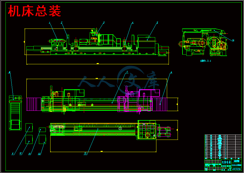
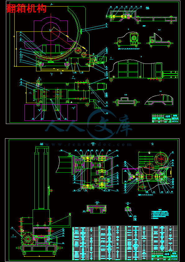
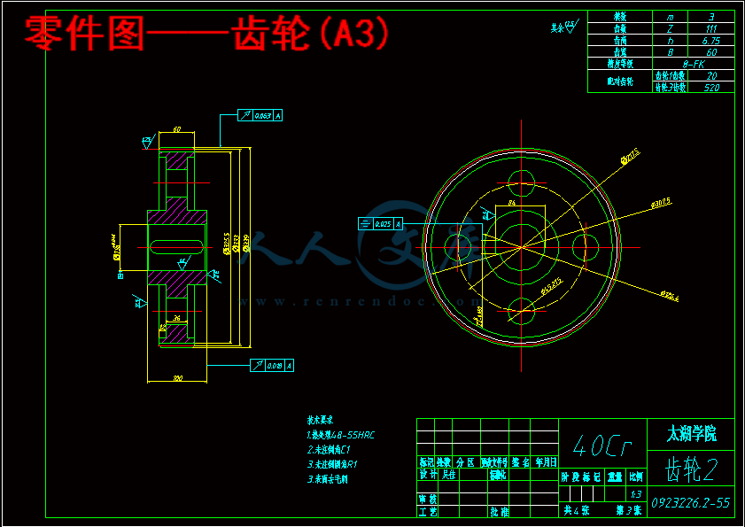
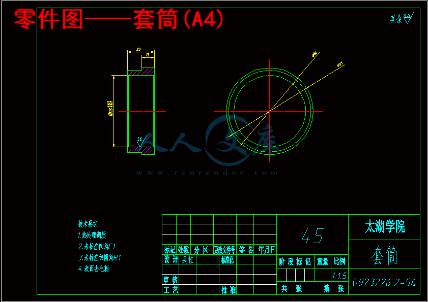
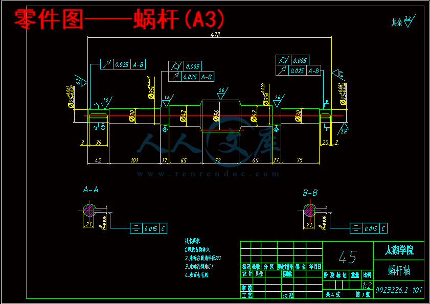
零件图——齿轮(A3).dwg
零件图——齿轮(A3).dwg

MKZ84125轧辊磨床轴承箱体翻转机构设计【7张CAD图纸+全套毕业论文】

收藏

压缩包内文档预览:
预览图
编号:439327    类型:共享资源    大小:1.99MB    格式:RAR    上传时间:2015-06-05 上传人:好资料QQ****51605 IP属地:江苏
45
积分
关 键 词:
mkz84125 轧辊 磨床 轴承 箱体 翻转 机构 设计
资源描述:

摘  要

自动数控磨床是钢材板材轧制生产线的重要配套设备,其磨削精度和磨削效率直接影响钢板的轧制质量与生产效率。它的作用是进行各种性质不同的钢材板材磨削,主要应用于钢材、铝箔和造纸行业等。然而其在磨削工作辊的过程中,两端的轴承箱体会与砂轮架发生干涉,而频繁的装卸轴承箱体则会使加工过程变得繁琐,因此设计了翻箱机构,将工件翻转90度。设计翻箱机构,包括翻箱机构的工作原理、机床各部件的组成、其操作要求和方法以及翻箱机构技术要求进行了概述,并详细设计了MKZ84125轧辊磨床的翻箱机构,其中包括法案的选择,电机的确定以及蜗轮蜗杆与各个轴以及齿轮的选择并画出了机床总装图,翻箱机构总装配图以及部分重要零件的部件图。其设计过程主要特点是采用三相异步电动机带动蜗轮蜗杆以及齿轮传动,以达到将工件翻转90度的效果,方便磨床加工。翻箱机构结构简单紧凑,操作简单,维护方便,翻转工件效率高。


关键词:翻箱机构;三相异步电动机;蜗轮蜗杆;齿轮传动


Abstract

The automatic CNC grinding machine is an important corollary equipment which rolls production line by steel and sheet metals. Its grinding accuracy and efficiency directly affect the quality of steel rolling and its production efficiency. Its role is to grind the various properties of steel and sheet metals, it mainly used in steel, aluminum foil, paper industry and etc. However, during the process of grinding, the bearing boxes of both sides will interfere with the wheel frame, and loading and unloading the bearing boxes frequently will make the process more complicated, so I designed the box turnover mechanism, it can let the workpiece rotate 90 degrees. Designing the box turnover mechanism, it consists of its working principle, the composition of each part of machine tool, its operating requirements and methods and providing an overview of technical requirements of the box turnover mechanism. What’s more, I also designed the box turnover mechanism of MKZ84125 rolling grinder. It involves the choice of the Act, the determination of motors and the selection of worms, each shaft and gears. In addition, I draw the assembly chart of machine, the general assembly chart of the box turnover mechanism and the parts diagram of some important parts. The main features of designing process are adopting the three-phase asynchronous motor to drive the worms and using the two-stage gears to drive to reach the effect which let the workpiece rotate 90 degrees. It will convenient the process. The structure of the box turnover mechanism is simple and compact. It can operate simply, maintain easily and the workpiece is efficient.


Key words: box turnover mechanism; three-phase asynchronous motor; worms; stage gears


目  录

摘  要III

ABSTRACTIV

目  录V

1 绪论1

1.1 立题依据1

1.2 翻箱机构的研究现状1

2 MKZ84125机床总体设计4

2.1 机床的技术参数4

2.2 机床总体布局设计4

2.2.1 布局方案的选择4

2.2.2 各部件的布局5

2.3 机床各部件的方案介绍5

2.3.1 床身5

2.3.2 头架6

2.3.3 尾架6

2.3.4 砂轮主轴系统7

2.3.5 砂轮架7

2.3.6 供油系统7

2.3.7 中心架8

2.3.8 CNC测量系统8

3 轴承箱体翻转机构设计9

3.1 设计的基本参数9

3.2 翻箱方案的选择9

3.3 翻箱机构的总体设计9

3.4 电动机的选择10

3.4.1 选择电动机类型10

3.4.2 选择电动机的容量10

3.4.3 电动机转速的确定11

3.5 总传动比和分配各级传动比的计算12

3.6 传动装置的运动和动力参数的计算12

3.6.1 各轴转速12

3.6.2 各轴功率12

3.6.3 各轴转矩12

3.7 传动零件的设计计算13

3.7.1 联轴器的类型的选择13

3.7.2 蜗杆传动的设计13

3.7.3 第一级齿轮传动的设计16

3.7.4 第二级齿轮传动的设计19

3.8 翻箱机构的结构设计21

3.8.1 轴1的结构设计21

3.8.2 轴2的结构设计22

3.8.3 轴3的结构设计23

3.8.4 翻箱机构其余部分的结构设计24

4 轴的校核26

4.1 轴1的校核26

4.2 轴2的校核28

4.3 轴3的校核30

5 结论与展望33

5.1 结论33

5.2 不足之处及未来展望33

致谢34

参考文献35

1 绪论

1.1 立题依据

该课题来自于无锡上机磨床有限公司的生产实际。

MKZ84125轧辊磨床它的磨削机理具有一般大型外圆磨床特点,但又不同于一般的外圆磨床的运动复杂得多,除砂轮与工件辊作相对回转运动外,还要求砂轮、工件二者作相对纵向运动的同时,作一定的径向相对位移,而且这个径向位移是不同于磨削锥度的复合运动。因此,它的传动机构比较复杂,机床工作精度要求也较高。工作辊是在造纸厂和轧钢厂的生产中用来轧制纸张和钢板的重要部件。其工作情况如图1.1所示。


图1.1 轧辊磨床工作辊工作示意图

由于工作辊在使用过程中磨损较快,平均两到三个小时就要进行修整磨削,否则将达不到所要求的加工精度。自动数控轧辊磨床在磨削工作辊的过程中,两端的轴承箱体会与砂轮架发生干涉,从而影响加工精度,而频繁的装卸轴承箱体则会使加工过程变得繁琐。

现在有客户提出希望上机磨床有限公司在设计轧辊磨床的同时能配上在线翻箱机构,在磨削工作辊时将轴承箱体翻转90°,既避免了在加工过程中轴承箱体和砂轮架干涉,又保证了加工的效率。


内容简介:
编号无锡太湖学院毕业设计(论文)相关资料题目: MKZ84125轧辊磨床轴承 箱体翻转机构设计 信机 系 机械工程及自动化专业学 号: 0923226学生姓名: 吴 佳 指导教师: 尤丽华 (职称:副教授 ) (职称: )2013年5月25日目 录一、毕业设计(论文)开题报告二、毕业设计(论文)外文资料翻译及原文三、学生“毕业论文(论文)计划、进度、检查及落实表”四、实习鉴定表无锡太湖学院毕业设计(论文)开题报告题目: MKZ84125轧辊磨床轴承 箱体翻转机构设计 机械 系 机械工程及自动化 专业学 号: 0923226 学生姓名: 吴 佳 指导教师: 尤丽华 (职称:副教授 ) (职称: )2012年11月25日 课题来源本课题来自于无锡上机磨床有限公司的生产实际。该公司设计生产的自动数控轧辊磨床在磨削工作辊的过程中,两端的轴承箱体会与砂轮架发生干涉,而频繁的装卸轴承箱体则会使加工过程变得繁琐。为了解决这个问题,本课题要设计一个轧辊磨床翻转机构,在磨削工作辊时将轴承箱体翻转90,既避免了在加工过程中轴承箱体和砂轮架干涉,又保证了加工的效率。科学依据(包括课题的科学意义;国内外研究概况、水平和发展趋势;应用前景等)十八世纪30年代,为了适应钟表、自行车、缝纫机和枪械等零件淬硬后的加工,英国、德国和美国分别研制出使用天然磨料砂轮的磨床。这些磨床是在当时现成的机床如车床、刨床等上面加装磨头改制而成的,它们结构简单,刚度低,磨削时易产生振动,要求操作工人要有很高的技艺才能磨出精密的工件。1876年在巴黎博览会展出的美国布朗-夏普公司制造的万能外圆磨床,是首次具有现代磨床基本特征的机械。它的工件头架和尾座安装在往复移动的工作台上,箱形床身提高了机床刚度,并带有内圆磨削附件。1883年,这家公司制成磨头装在立柱上、工作台作往复移动的平面磨床。1900年前后,人造磨料的发展和液压传动的应用,对磨床的发展有很大的推动作用。随着近代工业特别是汽车工业的发展,各种不同类型的磨床相继问世。例如20世纪初,先后研制出加工气缸体的行星内圆磨床、曲轴磨床、凸轮轴磨床和带电磁吸盘的活塞环磨床等。自动测量装置于1908年开始应用到磨床上。到了1920年前后,无心磨床、双端面磨床、轧辊磨床、导轨磨床,珩磨机和超精加工机床等相继制成使用;50年代又出现了可作镜面磨削的高精度外圆磨床;60年代末又出现了砂轮线速度达6080米/秒的高速磨床和大切深、缓进给磨削平面磨床;70年代,采用微处理机的数字控制和适应控制等技术在磨床上得到了广泛的应用。随着高精度、高硬度机械零件数量的增加,以及精密铸造和精密锻造工艺的发展,磨床的性能、品种和产量都在不断的提高和增长。磨床是各类金属切削机床中品种最多的一类,主要类型有外圆磨床、内圆磨床、平面磨床、无心磨床、工具磨床等。外圆磨床是使用的最广泛的,能加工各种圆柱形和圆锥形外表面及轴肩端面的磨床。万能外圆磨床还带有内圆磨削附件,可磨削内孔和锥度较大的内、外锥面。不过外圆磨床的自动化程度较低,只适用于中小批单件生产和修配工作。内圆磨床的砂轮主轴转速很高,可磨削圆柱、圆锥形内孔表面。普通内圆磨床仅适于单件、小批生产。自动和半自动内圆磨床除工作循环自动进行外,还可在加工中自动测量,大多用于大批量的生产中。 平面磨床的工件一般是夹紧在工作台上,或靠电磁吸力固定在电磁工作台上,然后用砂轮的周边或端面磨削工件平面的磨床;无心磨床通常指无心外圆磨床,即工件不用顶尖或卡盘定心和支承,而以工件被磨削外圆面作定位面,工件位于砂轮和导轮之间,由托板支承,这种磨床的生产效率较高,易于实现自动化,多用在大批量生产中。 工具磨床是专门用于工具制造和刀具刃磨的磨床,有万能工具磨床、钻头刃磨床、拉刀刃磨床、工具曲线磨床等,多用于工具制造厂和机械制造厂的工具车间。砂带磨床是以快速运动的砂带作为磨具,工件由输送带支承,效率比其他磨床高数倍,功率消耗仅为其他磨床的几分之一,主要用于加工大尺寸板材、耐热难加工材料和大量生产的平面零件等。专门化磨床是专门磨削某一类零件,如曲轴、凸轮轴、花键轴、导轨、叶片、轴承滚道及齿轮和螺纹等的磨床。除以上几类外,还有珩磨机、研磨机、坐标磨床和钢坯磨床等多种类型。由于长期以来对新技术的应用相对滞后,国内机床产品的总体技术水平比之先进国家同类型机床还有着相当大的差距,劳动生产率低下,在国际市场中竞争力不足,经济效益不高。在国外高档机床大举进攻中国市场的情况下,我们只有以积极的姿态面对这一严峻的形势。尽快应用先进的设计技术,能快速开发出结构合理、自动化水平高、加工精度高、低振动、低成本的机床新产品响应市场,我国的机床工业才有出路。为了达到这一目的,掌握先进的机床设计方法就显得尤为重要。我国机床工业的竟争能力的提高也就取决于机床新品的开发和关键技术的研究、掌握、应用和迅速推广。随着我国加入世界贸易组织和全球经济一体化环境的形成,机床行业的市场竞争将会愈演愈烈。目前,国内外机床产品技术水平之间的差距仍然很大,主要表现为:产品仿制多,创新少,市场竞争力不足,利润低:设计方法落后,机床结构设计,尚处于传统的经验、静态、类比的设计阶段,很少考虑结构动、静态特性对机床产品性能产生的影响,产品精度低,质量难以保证;设计周期长,成功率低,反复设计、试制与修改,产品更新换代慢,且成本高。研究内容轧辊磨床为金属切削机床,由床身、头架、尾架、托架、纵横拖板、磨头、测量架及电气数控系统组成,分为承载系统、驱动系统、磨削系统、测量系统和控制系统五个子系统。工件由头架、尾架和托架支撑,并由头架驱动旋转。数控系统根据轧辊表面母线的数学模型,控制机床作多轴复合运动,在运动过程中实现砂轮对辊面金属的磨削。在线测量系统实时地将测量数据反馈给磨床控制系统,并由控制系统对机床出闭环控制,从而完成对工件的精密加工。床身:采用砂轮床身与工件床身分离的结构。床身调整垫铁间距短,刚性强,床身精度不易变化。砂轮床身为大约为1200mm导轨间距的宽体床身,配备的伸缩式不锈钢防护罩保证永不生锈,安装在砂轮床身内的精密滚珠丝杆,用于驱动大拖板(Z轴)。头架:采用三级三角皮带传动保证了传动的平稳和精度;使用交流主轴电机驱动能使头架实现正向和反向旋转;头架的位置控制功能,可实现拨盘角度自动定位,方便轧辊的吊装,减少辅助时间。头架润滑系统选用了油脂泵,可实现自动定时给油。 尾架:移动采用电动驱动方式,液压自动锁紧。尾架配备大行程(1000mm)液压套筒。砂轮主轴系统:前后径后轴承均采用高精度动静压轴承,主轴轴向采用高精度推力轴承。另外,在后轴承设计中增强了工作腔动静压轴承的静态压力效果,以克服较大皮带拉力对轴瓦造成的损伤。主轴动静压轴承具有回转精度高,稳定性好,动态刚性强,不易振动等特点。 磨架及其进给机构:磨架采用单层整体结构,具有很高的刚性,磨架导轨为贴塑静压导轨,磨架进给机构由带减速装置的西门子交流伺服电机和经过精确预拉伸的精密滚珠丝杆副组成,具有很高的进给精度和灵敏度。拖板(Z轴):拖板采用V-平形形式的贴塑静压导轨,拖板进给机构由带减速装置的西门子交流伺服电机和经过精确预拉伸精密滚珠丝杆副组成,由数控系统通过交流伺服电机和圆光栅实现拖板的闭环位置控制。拖板采用滚珠丝杆传动,与国内外同类磨床所采用的传统齿轮齿条传动相比,具有机械传动链短、运动平稳、传动精度高、间隙小等优点。头架控制系统:头架采用西门子1PH7型交流主轴电机驱动,内装西门子Sine/Cos1Vpp,2048 S/R光电编码器,完成头架速度及位置的闭环控制。头架可实现正向和反向旋转以及拨盘角度自动定位。交流主轴电机的采用使头架电机的维护工作量大大减少。针对轧辊驱动的特点头架采用了低额定转速、大启动扭矩的交流主轴电机,在保证重型轧辊启动需要的同时节约宝贵的能源。砂轮控制系统:砂轮采用西门子1PH7型交流主轴电机驱动,内装西门子Sine/Cos1Vpp,2048 S/R光电编码器,完成砂轮速度及位置的闭环控制。砂轮可实现正向和反向旋转以及角度自动定位。另外,交流主轴电机的采用极大地方便了砂轮电机的维护。砂轮采用了高达100KW的交流主轴电机,保证了磨床具有强力磨削能力,满足用户的轧辊快速大负荷加工要求。 电气控制柜及柜内配电系统和控制元件:为保证磨床电气系统的整体可靠性,从电气控制柜箱壳到柜内的配电系统以及保护元件、开关元件、控制元件全部采用进口的国际名牌产品(西门子、威图)。拟采取的研究方法、技术路线、实验方案及可行性分析通过对MKZ84125自动数控轧辊磨床实地考察,总结得出该磨床的基本结构,工作方式与原理,然后根据考察的结果,再查阅相关书籍后对其进行整体设计的基础,再根据上机磨床厂给定的关于机床的尺寸参数,翻箱动作的具体要求以及大连重工集团有限公司设计的待加工工作辊的相关资料,对在MKZ84125自动数控轧辊磨床上使用的翻箱机构进行设计,进行初步设计。交由指导老师检查,修改。完成后,再对主要载荷部件进行校核。最后出主要零件的零件图,编写设计说明书。可行性分析:轧辊磨床通常是用来磨削工作辊的。由于工作辊在使用过程中磨损较快,平均两到三个小时就要进行修整磨削,否则将达不到所要求的加工精度,所以轧辊磨床除用于在加工工作辊时来磨削工作辊外,还需要在生产中用于对工作辊进行频繁的修磨。当轧辊磨床用于加工工作辊时,工作辊是在没有和其两端的轴承箱体进行装配的情况下,单独在磨床上进行磨削的。而工作辊在使用中两端会装配有轴承箱体,如果对工作辊进行带箱磨削,则由于轴承箱体的结构和存在一定的偏心,在重力作用下摆放的自然位置会和砂轮架发生干涉,使工作辊的工作表面不能得到完整的修磨。因此对工作辊进行修磨前要将轴承箱体拆卸下来,需要耗费大量的时间和人力。由此可见,该课题方案切实可行。研究计划对于本课题,初步确定按以下步骤进行:(1)应先通过查找文献了解机床的基本结构,熟悉机床的具体工作原理;(2)完成整机的总体布局设计,并绘制相应的二维图纸;(3)完成翻箱机构的设计,绘制相应的二维装配图;(4)完成部分零件图设计。预期成果由于工作辊在使用过程中磨损较快,平均两到三个小时就要进行修整磨削,否则将达不到所要求的加工精度,所以轧辊磨床除用于在加工工作辊时来磨削工作辊外,还需要在生产中用于对工作辊进行频繁的修磨。当轧辊磨床用于加工工作辊时,工作辊是在没有和其两端的轴承箱体进行装配的情况下,单独在磨床上进行磨削的。而工作辊在使用中两端会装配有轴承箱体,如果对工作辊进行带箱磨削,则由于轴承箱体的结构和存在一定的偏心,在重力作用下摆放的自然位置会和砂轮架发生干涉,使工作辊的工作表面不能得到完整的修磨。因此对工作辊进行修磨前要将轴承箱体拆卸下来,需要耗费大量的时间和人力。通过对该自动数控轧辊磨床上使用的翻箱机构进行设计,实现在磨削前将轴承箱体从自然位置翻转一定的角度,使其在磨削过程中不再和砂轮架发生干涉,从而实现带箱磨削,可大大提高用户在生产中的效率。已具备的条件和尚需解决的问题 设计过程中所需要的各种软硬件资源和相关产品实物照片。 相关文献资料的缺乏,对一些结构设计部分的具体设计指导,以及一些装配尺寸的确定。指导教师意见指导老师签名: 年 月 日 教研室(学科组、研究所)意见教研室主任签名: 年 月 日系意见教研室主任签名: 年 月 日Fundamentals of Mechanical DesignMechanical design means the design of things and systems of a mechanical naturemachines, products, structures, devices, and instruments. For the most part mechanical design utilizes mathematics, the materials sciences, and the engineering-mechanics sciences.The total design process is of interest to us. How does it begin? Does the engineer simply sit down at his desk with a blank sheet of paper? And, as he jots down some ideas, what happens next? What factors influence or control the decisions which have to be made? Finally, then, how does this design process end?Sometimes, but not always, design begins when an engineer recognizes a need and decides to do something about it. Recognition of the need and phrasing it in so many words often constitute a highly creative act because the need may be only a vague discontent, a feeling of uneasiness, of a sensing that something is not right.The need is usually not evident at all. For example, the need to do something about a food-packaging machine may be indicated by the noise level, by the variations in package weight, and by slight but perceptible variations in the quality of the packaging or wrap.There is a distinct difference between the statement of the need and the identification of the problem. Which follows this statement? The problem is more specific. If the need is for cleaner air, the problem might be that of reducing the dust discharge from power-plant stacks, or reducing the quantity of irritants from automotive exhausts.Definition of the problem must include all the specifications for the thing that is to be designed. The specifications are the input and output quantities, the characteristics of the space the thing must occupy and all the limitations on these quantities. We can regard the thing to be designed as something in a black box. In this case we must specify the inputs and outputs of the box together with their characteristics and limitations. The specifications define the cost, the number to be manufactured, the expected life, the range, the operating temperature, and the reliability.There are many implied specifications which result either from the designers particular environment or from the nature of the problem itself. The manufacturing processes which are available, together with the facilities of a certain plant, constitute restrictions on a designers freedom, and hence are a part of the implied specifications. A small plant, for instance, may not own cold-working machinery. Knowing this, the designer selects other metal-processing methods which can be performed in the plant. The labor skills available and the competitive situation also constitute implied specifications.After the problem has been defined and a set of written and implied specifications has been obtained, the next step in design is the synthesis of an optimum solution. Now synthesis cannot take place without both analysis and optimization because the system under design must be analyzed to determine whether the performance complies with the specifications.The design is an iterative process in which we proceed through several steps, evaluate the results, and then return to an earlier phase of the procedure. Thus we may synthesize several components of a system, analyze and optimize them, and return to synthesis to see what effect this has on the remaining parts of the system. Both analysis and optimization require that we construct or devise abstract models of the system which will admit some form of mathematical analysis. We call these models mathematical models. In creating them it is our hope that we can find one which will simulate the real physical system very well.Evaluation is a significant phase of the total design process. Evaluation is the final proof of a successful design, which usually involves the testing of a prototype in the laboratory. Here we wish to discover if the design really satisfies the need or needs. Is it reliable? Will it compete successfully with similar products? Is it economical to manufacture and to use? Is it easily maintained and adjusted? Can a profit be made from its sale or use?Communicating the design to others is the final, vital step in the design process. Undoubtedly many great designs, inventions, and creative works have been lost to mankind simply because the originators were unable or unwilling to explain their accomplishments to others. Presentation is a selling job. The engineer, when presenting a new solution to administrative, management, or supervisory persons, is attempting to sell or to prove to them that this solution is a better one. Unless this can be done successfully, the time and effort spent on obtaining the solution have been largely wasted.Basically, there are only three means of communication available to us. There are the written, the oral, and the graphical forms. Therefore the successful engineer will be technically competent and versatile in all three forms of communication. A technically competent person who lacks ability in any one of these forms is severely handicapped. If ability in all three forms is lacking, no one will ever know how competent that person is!The competent engineer should not be afraid of the possibility of not succeeding in a presentation. In fact, occasional failure should be expected because failure or criticism seems to accompany every really creative idea. There is a great to be learned from a failure, and the greatest gains are obtained by those willing to risk defeat. In the find analysis, the real failure would lie in deciding not to make the presentation at all.Introduction to Machine DesignMachine design is the application of science and technology to devise new or improved products for the purpose of satisfying human needs. It is a vast field of engineering technology which not only concerns itself with the original conception of the product in terms of its size, shape and construction details, but also considers the various factors involved in the manufacture, marketing and use of the product.People who perform the various functions of machine design are typically called designers, or design engineers. Machine design is basically a creative activity. However, in addition to being innovative, a design engineer must also have a solid background in the areas of mechanical drawing, kinematics, dynamics, materials engineering, strength of materials and manufacturing processes.As stated previously, the purpose of machine design is to produce a product which will serve a need for man. Inventions, discoveries and scientific knowledge by themselves do not necessarily benefit people; only if they are incorporated into a designed product will a benefit be derived. It should be recognized, therefore, that a human need must be identified before a particular product is designed.Machine design should be considered to be an opportunity to use innovative talents to envision a design of a product is to be manufactured. It is important to understand the fundamentals of engineering rather than memorize mere facts and equations. There are no facts or equations which alone can be used to provide all the correct decisions to produce a good design. On the other hand, any calculations made must be done with the utmost care and precision. For example, if a decimal point is misplaced, an otherwise acceptable design may not function.Good designs require trying new ideas and being willing to take a certain amount of risk, knowing that is the new idea does not work the existing method can be reinstated. Thus a designer must have patience, since there is no assurance of success for the time and effort expended. Creating a completely new design generally requires that many old and well-established methods be thrust aside. This is not easy since many people cling to familiar ideas, techniques and attitudes. A design engineer should constantly search for ways to improve an existing product and must decide what old, proven concepts should be used and what new, untried ideas should be incorporated.New designs generally have “bugs” or unforeseen problems which must be worked out before the superior characteristics of the new designs can be enjoyed. Thus there is a chance for a superior product, but only at higher risk. It should be emphasized that if a design does not warrant radical new methods, such methods should not be applied merely for the sake of change.During the beginning stages of design, creativity should be allowed to flourish without a great number of constraints. Even though many impractical ideas may arise, it is usually easy to eliminate them in the early stages of design before firm details are required by manufacturing. In this way, innovative ideas are not inhibited. Quite often, more than one design is developed, up to the point where they can be compared against each other. It is entirely possible that the design which ultimately accepted will use ideas existing in one of the rejected designs that did not show as much overall promise.Psychologists frequently talk about trying to fit people to the machines they operate. It is essentially the responsibility of the design engineer to strive to fit machines to people. This is not an easy task, since there is really no average person for which certain operating dimensions and procedures are optimum.Another important point which should be recognized is that a design engineer must be able to communicate ideas to other people if they are to be incorporated. Initially the designer must communicate a preliminary design to get management approval. This is usually done by verbal discussions in conjunction with drawing layouts and written material. To communicate effectively, the following questions must be answered:(1) Does the design really serve a human need?(2) Will it be competitive with existing products of rival companies? (3) Is it economical to produce?(4) Can it be readily maintained?(5) Will it sell and make a profit?Only time will provide the true answers to the preceding questions, but the product should be designed, manufactured and marketed only with initial affirmative answers. The design engineer also must communicate the finalized design to manufacturing through the use of detail and assembly drawings.Quite often, a problem well occur during the manufacturing cycle. It may be that a change is required in the dimensioning or telegramming of a part so that it can be more readily produced. This falls in the category of engineering changes which must be approved by the design engineer so that the product function will not be adversely affected. In other cases, a deficiency in the design may appear during assembly or testing just prior to shipping. These realities simply bear out the fact that design is a living process. There is always a better way to do it and the designer should constantly strive towards finding that better way.MachiningTurning The engine lathe, one of the oldest metal removal machines, has a number of useful and highly desirable attributes. Today these lathes are used primarily in small shops where smaller quantities rather than large production runs are encountered.The engine lathe has been replaced in todays production shops by a wide variety of automatic lathes such as automatic of single-point tooling for maximum metal removal, and the use of form tools for finish and accuracy, are now at the designers fingertips with production speeds on a par with the fastest processing equipment on the scene today.Tolerances for the engine lathe depend primarily on the skill of the operator. The design engineer must be careful in using tolerances of an experimental part that has been produced on the engine lathe by a skilled operator. In redesigning an experimental part for production, economical tolerances should be used.Turret Lathes Production machining equipment must be evaluated now, more than ever before, in terms of ability to repeat accurately and rapidly. Applying this criterion for establishing the production qualification of a specific method, the turret lathe merits a high rating.In designing for low quantities such as 100 or 200 parts, it is most economical to use the turret lathe. In achieving the optimum tolerances possible on the turret lathe, the designer should strive for a minimum of operations.Automatic Screw Machines Generally, automatic screw machines fall into several categories; single-spindle automatics, multiple-spindle automatics and automatic chucking machines. Originally designed for rapid, automatic production of screws and similar threaded parts, the automatic screw machine has long since exceeded the confines of this narrow field, and today plays a vital role in the mass production of a variety of precision parts. Quantities play an important part in the economy of the parts machined on the automatic to set up on the turret lathe than on the automatic screw machine. Quantities less than 1000 parts may be more economical to set up on the turret lathe than on the automatic screw machine. The cost of the parts machined can be reduced if the minimum economical lot size is calculated and the proper machine is selected for these quantities.Automatic Tracer Lathes Since surface roughness depends greatly upon material turned, tooling, and fees and speeds employed, minimum tolerances that can be held on automatic tracer lathes are not necessarily the most economical tolerances.Is some case, tolerances of 0.05mm are held in continuous production using but one cut. Groove width can be held to 0.125mm on some parts. Bores and single-point finishes can be held to 0.0125mm. On high-production runs where maximum output is desirable, a minimum tolerance of 0.125mm is economical on both diameter and length of turn.Milling With the exceptions of turning and drilling, milling is undoubtedly the most widely used method of removing metal. Well suited and readily adapted to the economical production of any quantity of parts, the almost unlimited versatility of the milling process merits the attention and consideration of designers seriously concerned with the manufacture of their product.As in any other process, parts that have to be milled should be designed with economical tolerances that can be achieved in production milling. If the part is designed with tolerances finer than necessary, additional operations will have to be added to achieve these tolerancesand this will increase the cost of the part.Grinding is one of the most widely used methods of finishing parts to extremely close tolerances and low surface roughness. Currently, there are grinders for almost for almost every type of grinding operation. Particular design features of a part dictate to a large degree the type of grinding machine required. Where processing costs are excessive, parts redesigned to utilize a less expensive, higher output grinding method may be well worthwhile. For example, wherever possible the production economy of center less grinding should be taken advantage of by proper design consideration.Although grinding is usually considered a finishing operation, it is often employed as a complete machining process on work which can be ground down from rough condition without being turned or otherwise machined. Thus many types of forgings and other parts are finished completely with the grinding wheel at appreciable savings of time and expense.Classes of grinding machines include the following: cylindrical grinders, center less grinders, internal grinders, surface grinders, and tool and cutter grinders.The cylindrical and center less grinders are for straight cylindrical or taper work; thus splices, shafts, and similar parts are ground on cylindrical machines either of the common-center type or the center less machine.Thread grinders are used for grinding precision threads for thread gages, and threads on precision parts where the concentricity between the diameter of the shaft and the pitch diameter of the thread must be held to close tolerances.The internal grinders are used for grinding of precision holes, cylinder bores, and similar operations where bores of all kinds are to be finished.The surface grinders are for finishing all kinds of flat work, or work with plain surfaces which may be operated upon either by the edge of a wheel or by the face of a grinding wheel. These machines may have reciprocating or rotating tables.机械设计基础机械设计基础是指机械装置和机械系统机器、产品、结构、设备和仪器的设计。大部分机械设计需要利用数学、材料科学和工程力学知识。我们对整个设计过程感兴趣。它是怎样开始的?工程师是不是仅仅坐在铺着白纸的桌旁就可以开始设计了呢?当他记下一些设想后,下一步应该做些什么?什么因会影影响或者控制着应该做出的决定?最后,这一设计过程是怎样结束的呢?有时,虽然并不总是如此,工程师认识到一种需要并且决定对此做一些工作时,设计就开始了。认识到这种需要,并用语言将其清楚地叙述出来,常常是一种高度创造性的工作。因为这种需要可能只是一个模糊的不满,一种不舒服的感觉,或者是感觉到了某些东西是不正确的。这种需要往往不是很明显的。例如,对食品包装机械进行改进的需要,可能是由于噪音过大、包装重量的变化、包装质量的微小的但是能够察觉得出来的变化等表现出来的。叙述某种需要和随后要解决的问题之间有着明显的区别。要解决的问题是比较具体的。如果需要干净的空气,要解决的问题可能是降低发电厂烟囱的排尘量,或者是降低汽车排除的有害气体。确定问题阶段应该制订设计对象所有的要求。这些设计要求包括输入量、输出两特性、设计对象所占据的空间尺寸以及这些参量的所有制约因素。我们可以把设计对象看作是黑箱中的某种东西。在这种情况下,我们必须具体确定黑箱的输入和输出,以及它们的特性和制约因素。这些设计要求将规定生产成本、产量、预期寿命、工作范围、操作温度和可靠性。还存在着许多由于设计人员所处的特定环境或者由于问题本身的性质所产生的隐含设计要求。某个工厂中可利用的制造工艺和设备会对设计人员的工作有所限制,因而成为隐含的设计要求的一部分。例如,一个小工厂中可能没有冷变形加工机械设备。因此,设计人员就必须选择这个工厂中能够进行的其他的金属加工方法。工人的技术水平和市场上的竞争情况也是隐含的设计要求的组成部分。在确定了要解决的问题,并且形成了一系列的书面的和隐含的设计要求之后,设计工作的下一阶段是进行综合以获得最优的结果。因为只有通过对所设计的系统进行分析,才能确定其性能是否满足设计要求。因此,不进行分析和优化就不能进行综合。设计工作是一个反复进行的过程。在这个过程中,我们要经历几个阶段,在对结果进行评价后,再返回到前面的阶段。因此,我们可以先综合系统中的几个零件,对它们进行分析和优化,然后再进行综合,看它们对系统的其他部分有时么影响。分析和优化都要求我们建立或者做出系统的抽象模型,以便对此进行数学分析。我们将这些模型称为数学模型。在建立数学模型时,我们希望能够找到一个可以很好地模拟实际物理系统的数学模型。评价是整个设计过程中的一个重要阶段。评价是对一个成功的设计的最后检验,通常包括样机的实验室实验。在此阶段我们希望弄清楚设计能否真正满足所有的要求。它是否可靠?在与类似的产品的竞争中它能否获胜?制造和使用这种产品是否经济?它是否易于维护和调整?能否从它的销售或使用中获得利润?与其他人就设计方案进行交流和沟通是设计过程的最后和关键阶段。毫无疑问,有许多伟大的设计、发明或创造之所以没有为人类所利用,就是因为创造者不善于或者不愿意向其他人介绍自己的成果。提出方案是一种说服别人的工作。当一个工程师向经营、管理部门或者其主管人员提出自己的新方案时,就是希望向他们说明或者证明自己的方案是比较好的。只有成功地完成这项工作,为得出这个方案所花费的大量时间和精力才不会被浪费掉。人们基本上只有三种表达自己思想的方式,即文字材料、口头表述和绘图。因此,一个优秀的工程师除了掌握技术之外,还应该精通这三种表达方式。如果一个技术能力很强的人在上述三种表达方式中的某一种的能力较差,他就会遇到很大的困难。如果上述三种能力都很差,那将永远没有人知道他是一个多么能干的人!一个有能力的工程师不应该害怕在提出自己的方案时遭到失败的可能性。事实上,偶然的失败肯定会发生的,因为每一个真正有创造性的设想似乎总是有失败或批评伴随着它。从一次失败中可以学到很多东西,只有不怕遭受失败的人们才能取得最大的收获。总之,决定不把方案提交出来,才是真正的失败。机械设计概论机械设计是一门通过设计新产品或者改进产品来满足人类需求的应用技术科学。它是一个广阔的工程技术领域,不仅要研究产品在尺寸、形状和详细结构等方面的基本构思,还要考虑产品在制造、销售和使用等方面的有关问题。进行各种机械设计工作的人员通常被称为设计人员或者设计工程师。机械设计是一项创造性的工作。设计工程师不仅在工作上要有创新性,还必须在机械制图、运动学、工程材料、材料力学和机械制造工艺等方面具有深厚的基础知识。如前面所述,机械设计的目的是生产能够满足人类需求的产品。发明、发现和科学知识本身并不一定能给人类带来益处,只有当它们被用在产品上才能产生效益。因而,应该认识到再一个特定产品进行设计之前,必须先确定人们是否需要这种产品。应当把机械设计看成是设计人员运用创造性的才能进行产品设计、系统分析和制订产品的制造工艺的一个良机。掌握工程基础知识要比熟记一些数据和公式更为重要。仅仅使用数据和公式是不足以再一个好的设计中做出所需的全部决定。另一方面,应该认真精确地进行所有运算。例如,即使将一个小数点的位置放错,也会使正确的设计变成错误的。一个好的设计人员应该勇于提出新的想法,而且愿意承担一定的风险,当新的方法不适用时,就恢复采用原来的方法。因此,设计人员必须要有耐心,因为所花费的时间和努力并不能保证带来成功。一个全新的
温馨提示:
1: 本站所有资源如无特殊说明,都需要本地电脑安装OFFICE2007和PDF阅读器。图纸软件为CAD,CAXA,PROE,UG,SolidWorks等.压缩文件请下载最新的WinRAR软件解压。
2: 本站的文档不包含任何第三方提供的附件图纸等,如果需要附件,请联系上传者。文件的所有权益归上传用户所有。
3.本站RAR压缩包中若带图纸,网页内容里面会有图纸预览,若没有图纸预览就没有图纸。
4. 未经权益所有人同意不得将文件中的内容挪作商业或盈利用途。
5. 人人文库网仅提供信息存储空间,仅对用户上传内容的表现方式做保护处理,对用户上传分享的文档内容本身不做任何修改或编辑,并不能对任何下载内容负责。
6. 下载文件中如有侵权或不适当内容,请与我们联系,我们立即纠正。
7. 本站不保证下载资源的准确性、安全性和完整性, 同时也不承担用户因使用这些下载资源对自己和他人造成任何形式的伤害或损失。
提示  人人文库网所有资源均是用户自行上传分享,仅供网友学习交流,未经上传用户书面授权,请勿作他用。
关于本文
本文标题:MKZ84125轧辊磨床轴承箱体翻转机构设计【7张CAD图纸+全套毕业论文】
链接地址:https://www.renrendoc.com/p-439327.html

官方联系方式

2:不支持迅雷下载,请使用浏览器下载   
3:不支持QQ浏览器下载,请用其他浏览器   
4:下载后的文档和图纸-无水印   
5:文档经过压缩,下载后原文更清晰   
关于我们 - 网站声明 - 网站地图 - 资源地图 - 友情链接 - 网站客服 - 联系我们

网站客服QQ:2881952447     

copyright@ 2020-2025  renrendoc.com 人人文库版权所有   联系电话:400-852-1180

备案号:蜀ICP备2022000484号-2       经营许可证: 川B2-20220663       公网安备川公网安备: 51019002004831号

本站为文档C2C交易模式,即用户上传的文档直接被用户下载,本站只是中间服务平台,本站所有文档下载所得的收益归上传人(含作者)所有。人人文库网仅提供信息存储空间,仅对用户上传内容的表现方式做保护处理,对上载内容本身不做任何修改或编辑。若文档所含内容侵犯了您的版权或隐私,请立即通知人人文库网,我们立即给予删除!