连接盖板冲裁模具设计.ppt

连接盖板冲裁模具设计【26张CAD图纸+毕业答辩论文】【冲压模具】

收藏

资源目录
跳过导航链接。
连接盖板冲裁模具设计【全套CAD图纸+毕业答辩论文】【冲压模具】.rar
连接盖板冲裁模具设计.ppt---(点击预览)
文志刚毕业设计(论文)开题报告.doc---(点击预览)
摘要文22.doc---(点击预览)
制件图.dwg---(点击预览)
A4-转动板.dwg---(点击预览)
A4-翘板固定块.dwg---(点击预览)
A4-翘板.dwg---(点击预览)
A4-滑块.dwg---(点击预览)
A4-支撑板.dwg---(点击预览)
A4-弹簧顶杆.dwg---(点击预览)
A4-压板.dwg---(点击预览)
A3-落料弯曲凸模.dwg---(点击预览)
A3-落料凹模.dwg---(点击预览)
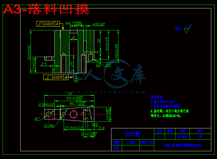
A3-落料凹摸.dwg---(点击预览)
A3-翘板顶块.dwg---(点击预览)
A3-滑块落料凸摸3.dwg---(点击预览)
A3-模柄.dwg---(点击预览)
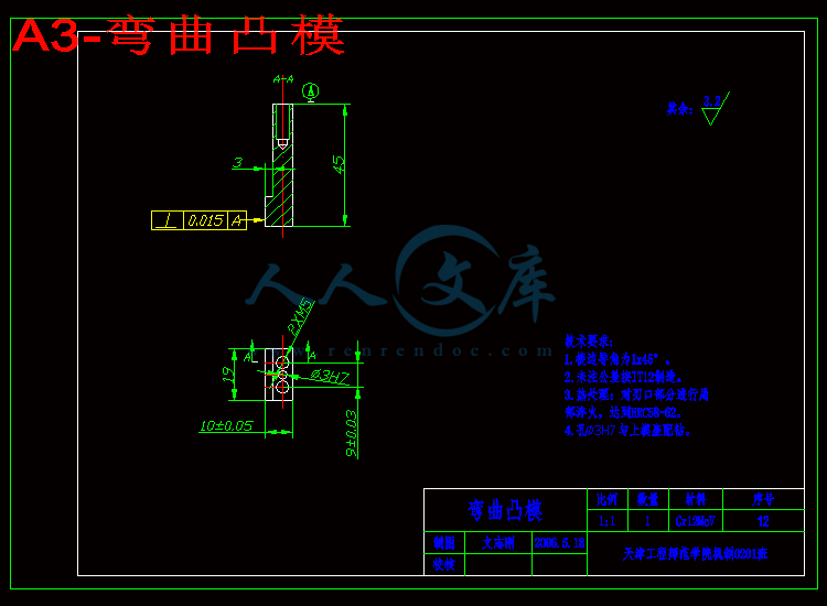
A3-弯曲凸模.dwg---(点击预览)
A3-导柱.dwg---(点击预览)
A3-导套.dwg---(点击预览)
A3-压料板.dwg---(点击预览)
A3-卸料板.dwg---(点击预览)
A3-凸模固定板.dwg---(点击预览)
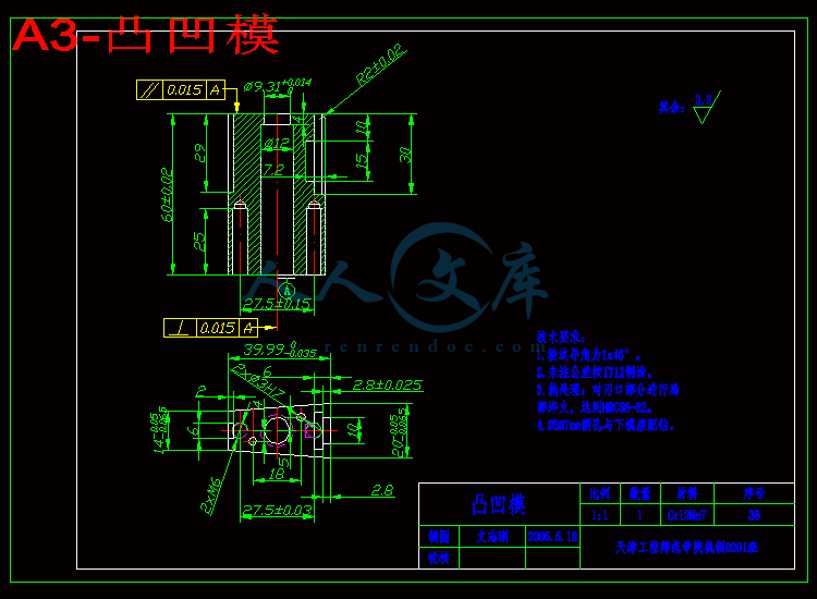
A3-凸凹模.dwg---(点击预览)
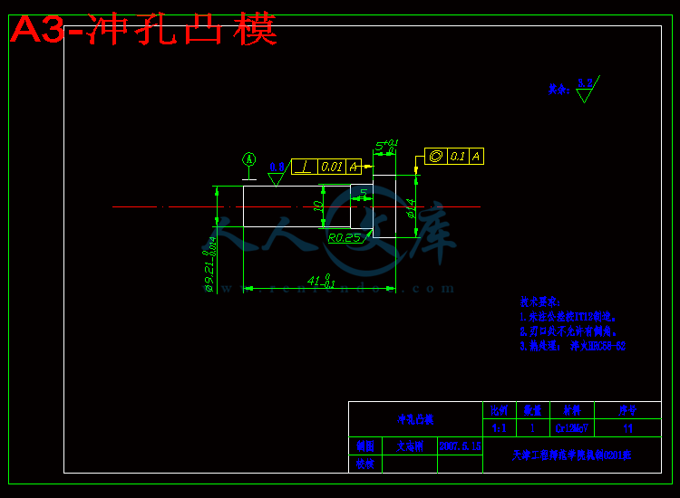
A3-冲孔凸模.dwg---(点击预览)
A3-上模垫板.dwg---(点击预览)
A2-下模座.dwg---(点击预览)
A2-上模座.dwg---(点击预览)
A1-装配图.dwg---(点击预览)
工艺卡1
论文
压缩包内文档预览:
预览图 预览图 预览图 预览图 预览图 预览图 预览图 预览图 预览图 预览图 预览图 预览图 预览图 预览图 预览图 预览图 预览图
编号:443466    类型:共享资源    大小:1.56MB    格式:RAR    上传时间:2015-06-24 上传人:好资料QQ****51605 IP属地:江苏
45
积分
关 键 词:
连接 盖板 模具设计 全套 cad 图纸 毕业 答辩 论文 冲压 模具
资源描述:

摘要

模具发展水平是体现当代工业国家发展水平的一个非常重要衡量标准,作为机械专业的学生,了解和认识模具对于国家的模具发展水平的提高是一个非常重要的发展基础,也是全面提高所学专业知识的途径之一。本文介绍和分析了冷冲模具的特点、结构和作用及它的发展趋势,主要内容为冲裁、弯曲等基本冲压工艺及其模具设计,既根据所给内容及工件要求对模具结构进行设计、零件排样,最佳方案选择,模具各主要部分力的计算,冲压设备的选择,弹性元件的计算及模架的选择,对主要工作机构进行合理的理论数值计算,及确定主要零件凸凹模刃口尺寸及公差,最终完成模具设计。通过本次设计,对于专业知识的实际综合运用能力,分析能力,实际问题的解决能力是一个重要的提高过程。  


关键词:模具结构,工艺力,弹性元件


ABSTRACT

Mold levels of development embodies contemporary industrial level of development of the country, a very important yardstick, as a mechanical professional students understanding and knowledge of our country's Die Mold raising its level of development is a very important foundation for the development, comprehensively improve the professional knowledge acquired one of the ways. This paper describes and analyzes the Die with the characteristics, structure and role and its development trend, mainly as blanking, Bending basic stamping and die design process, according to both the contents and requirements of the work piece to die structure for the design, Parts layout, the best options, die of the main part of the calculation, stamping equipment selection, elastic element of calculation and die-choice, the main organizations of reasonable theoretical numerical calculation, and identify key components of punch and die cutting edge dimensions and tolerances, and ultimately complete mold design. During this design expertise for the integrated use of the actual capabilities, analytical ability, the solution of practical problems is the ability to raise an important process.


Keywords: Die structure, process, the elastic element


目 录


第1章 绪论1

第2章 冲压加工概述2

2.1 冷冲压加工及冲压分类2

2.2 冲压技术的现状及发展方向3

第3章 冷冲压模具设计过程4

3.1冲压零件的技术要求4

3.2 冲压工艺设计4

3.3 主要工艺参数计算7

3.4 主要工作部分尺寸计算9

3.5 冲裁模主要零件设计12

3.6 卸料、出件、弹性元件装置的设计13

3.7 模具总体结构设计15

3.8 模具装配要点18

3.9 模具动作过程20

结 论22

参考文献23

致 谢24

附录1英文资料及中文翻译25

1英文资料25

2译文如下31

附录236


第1章 绪论


冲压工艺与冲压设备正在不断地发展,特别是精密冲压,高速冲压,多工位自动冲压以及液压成型,超塑性冲压等各种冲压工艺的迅速发展,把冲压的技术水平提高到了一个新高度。新型模具材料的采用,模具的推广,模具结构的改善及其精度的提高,显著地延长了模具的寿命和扩大冲压加工工艺范围。

 由于冲压工艺具有生产效率高、质量稳定、成本低以及可以加工复杂形状工件等一系列优点。在机械、汽车、国防、家用电器、以及日常生活用品等行业应用非常广泛,占有十分重要的地位。随着工业产品的不断发展和生产技术水平的不断提高,冲压模具作为各部分的重要的基础工艺装备将起到越来越大的作用。

冷冲压具有生产效率高,加工成本低,材料利用率高,产品的尺寸精度稳定,操作简单,易于实现机械化和自动化等。因而在批量生产中得到了广泛的应用,在现代化工业生产中占有十分重要的地位,是国防工业和民用工业生产中必不可少的加工方法,在电子产品中,冲压件约占80%-85%,在汽车、农业机械产品中,冲压件约占75%-80%,在轻工业产品中,冲压件占约95%以上,此外,在航空及航天工业生产中,冲压件也占有很大比例。

随着工业产品质量的不断提高,冲压零件日趋复杂化及规模化,冲压模具正向着高效、精密、长寿命、大型化方向发展,冲模制造难度日益增大,制造的种类也日益增多。模具的制造正由过去的劳动密集、依靠人工的手工技巧及采用传统机械加工设备的行业转变为技术密集型行业,从过去单一的机械加工时代转变成机械加工、电加工以及其他特种加工相结合的时代。特别是近几年来在国外已经发展起来、国内亦开始使用的冲压柔性制造单元(FMC)和冲压柔性制造系统(FMS)代表了冲压生产新的发展趋势。模具制造技术现代化是模具工业发展的基础。计算机技术、信息技术、自动化技术等先进技术正在不断向传统制造技术渗透、交叉、融合,形成先进制造技术。模具制造技术,已经发展成为技术密集型的综合加工技术。


内容简介:
零件名上模垫板序号44材料45数量1工序号工序名称工序内容所选设备1备料锻造毛坯,尺寸45mmX25mmX6mm2铣削加工铣削六面,成尺40mmX20mmX5.2mm铣床3热处理调质HRC28-32 4磨削磨削尺寸5.2mm两端面至图纸要求 磨床5钳工划线按图样划全部孔线平板、高度尺、钢板尺等6钻孔钻通孔9mm、5mm及2X6mm钻床7加工销孔2X3H7mm销孔,在试冲、调整后,与上模座、凸模固定板配钻、扩、铰加工至图面要求钻床加工工艺过程卡片零件名上模座序号3材料HT200数量1工序号工序名称工序内容所选设备1备料铸造毛坯2涂漆工涂底漆3刨削上下平面留0.5磨削余量刨床4磨削上下平面至图纸要求磨床5钳工划线按图样划全部孔线和槽线平板、高度尺、钢板尺等6车削车模柄孔60mm车床7铣削按图纸要求铣出60mm深15mm模柄孔及深23深13的槽8钻孔钻孔10mm沉孔16mm深13mm钻孔8X7mm沉孔11mm深13mm钻孔2X7mm通孔 与模柄配钻4XM6螺纹底孔,并攻螺纹钻通孔9mm及7X5.6mm,2X42mm留镗量钻床 9镗孔镗导套孔2X42mmH7坐标镗床10加工销孔2X4H7mm,2X8H7mm,5X3H7mm销孔在试冲、调整后,与上模垫板、凸模固定板及拨叉固定块配合,钻、扩、铰至图面要求钻床加工工艺过程卡片零件名下模座序号27材料HT200数量1工序号工序名称工序内容所选设备1备料铸造毛坯2涂漆工涂底漆3刨削上下平面留0.5磨削余量刨床4磨削上下平面至图纸要求磨床5钳工划线按图样划全部孔线,槽线平板、高度尺、钢板尺等6铣削按照图纸要求铣削深16mm,深5mm的槽铣床7钻孔钻孔4X6mm沉孔11mm深15mm,25mm钻孔4X4.5mm沉孔7mm深25mm钻孔4X7mm沉孔10mm深20mm钻孔2X7mm沉孔11mm深20mm钻孔4mm沉孔8mm深17mm钻孔4mm沉孔8.5mm深17mm钻孔2X4mm沉孔8.5mm深17mm钻通孔14mm,5.1mm钻螺纹孔4XM6的底孔钻通孔28X40mm留镗量钻床8镗孔镗导柱孔28X40mm,坐标镗床9加工销孔2X3H7mm销孔与翘板固定块配钻4X3H7mm销孔与压板配钻2X3H7mm销孔与凸凹模配钻钻床10攻螺纹攻4XM6螺纹孔钳工加工工艺过程卡片零件名冲孔凸模序号12材料Cr12MoV数量1工序号工序名称工序内容所选设备1备料锻造毛坯尺寸15mmX38mm3车削车削12mm、9mm外圆9mm外圆留磨削余量,做顶尖孔车床4热处理淬火达到HRC58-625磨削磨外圆至图样要求磨床加工工艺过程卡片零件名凸凹模序号39材料Cr12MoV数量1工序号工序名称工序内容所选设备1备料锻造毛坯尺寸45mmX25mmX63mm 2铣削铣六面,成尺30mmX20.3mmX60.3mm铣床3 钳工划线按图样划全部孔和形状线平板、高度尺、钢板尺等4铣削铣削T形槽,再铣长15mm深7.2mm的沉槽铣削槽,再铣长6mm深26mm的槽按照图纸铣六方体为(底边20mm、顶边14mm高37.7mm厚60mm)的梯形,各面各留0.3mm的磨量铣床5钻孔钻2XM6螺纹底孔钻床6攻螺纹攻螺纹2XM6钳工7磨削磨削各表面达到图纸形位公差要求,留0.05mm磨量磨床8钻孔钻9.7mm冲孔,12mm落料孔坐标镗床9热处理对工作刃及刃口部分进行局部淬火,达到HRC58-6210磨削磨各工作面尺寸至图纸要求磨床11钳工修整钳工修整保证冲裁间隙加工工艺过程卡片零件名凸模固定板序号41材料45数量1工序号工序名称工序内容所选设备1 备料锻造毛坯,尺寸45mmX25mmX11mm2铣削加工铣削六面,成尺14mm(顶边),20mm(底边)高40mm 厚10mm的梯形厚度10mm留0.30mm 磨削余量铣床3热处理调质HRC28-32 4磨削磨削尺寸10mm两端面至图纸要求磨床5 钳工划线按图样划全部孔线平板、高度尺、钢板尺等6钻孔钻孔3X4mm底孔并攻螺纹钻孔5.6mm沉孔9mm深6.5mm钻孔2X4mm沉孔7深6.5mm钻孔9mm沉孔13mm深5mm钻床7绞孔绞9mm至10H7mm钻床8加工销孔2X3H7mm销孔,在装配后与上模座、上模垫板配钻、扩、铰加工至图面要求钻床加工工艺过程卡片零件名卸料板序号38材料45数量1工序号工序名称工序内容所选设备1备料锻造毛坯,尺寸75mmX65mmX10mm2铣削铣削六面,根据图纸要求铣到尺寸70mmX60mmX5mm 铣床4 钻孔按图样划全部孔线、槽线平板、高度尺、钢板尺等 5铣削按照图纸要求铣出长59.44mm梯形槽铣床6钻孔4XM8螺纹孔,并攻螺纹钻床加工工艺过程卡片零件名压料板序号11材料45数量1工序号工序名称工序内容所选设备1备料锻造毛坯,尺寸45mmX25mmX11mm2铣削铣削六面,根据图纸要求铣20mmX14mmX38mm厚10的梯形,厚度10mm留磨削余量铣床3磨削磨削尺寸10mm两端面至图纸要求 磨床4 钻孔按图样划全部孔线平板、高度尺、钢板尺等 5钻孔2XM3,M5螺纹底孔,并攻螺纹钻孔13mm钻床加工工艺过程卡片零件名压板序号7材料45数量1工序号工序名称工序内容所选设备 1备料锻造毛坯,尺寸45mmX25mmX65mm2铣削铣削六面,加工至40mmX20mmX59mm的六面长方体铣床3钳工划线按图样划全部轮廓线与孔线平板、高度尺、钢板尺等4铣削铣削深39mm(59mm-20mm)的凹槽,15mmX40mm的尺寸5钻孔钻2X5mm孔留0.2的铰削余量钻2XM6mm螺纹底孔钻床6攻螺纹攻2XM6mm的螺纹孔钳工7铰孔铰4.8mm孔至5mm立式钻床8加工销孔2X3H7mm,销孔与下模座配合,钻、扩、铰至图面要求钻床加工工艺过程卡片零件名称序号毛坯规格毛坯材料数量模柄165mmX80mmQ2351上模座3170mmX150mmX35mmHT2001上模垫板4345mmX25mmX6mm451凸模固定板4145mmX25mmX11mm451压料板1145mmX25mmX11mm451落料凹模1598mmX65mmX50mmCr12MoV1落料弯曲凸模3328mmX19mmX65mmCr12MoV1弯曲凸模1325mmX15mmX48mmCr12MoV1凸凹模3945mmX25mmX63mmCr12MoV1滑块落料凸模1925mmX15mmX50mmCr12MoV1下模座27170mmX130mmX40mmHT2001翘板顶块4045mmX35mmX90mm451翘板固定块2935mmX35mmX46mm451翘板3150mmX15mmX15mm451压板845mmX40mmX65mm451支撑块4535mmX20mmX60mm452转动板1435mmX8mmX78mm451滑块2360mmX35mmX30mm451导柱 2133mmX165mm202弹簧顶杆2610mmX60mm451卸料板3875mmX65mmX10mm451导套1650mmX75mm202冲孔凸模1215mmX38mmCr12MoV1备料清单零件名导套序号16材料20数量1工序号工序名称工序内容所选设备1备料 毛坯尺寸50mmX75mm2车削车端面保持长度72mm,钻孔28mm留镗量车42mm外圆留磨量并倒角切3mmX0.5mm的槽至尺寸镗孔28mm的孔至27.6mm镗油槽,镗29的孔至图纸要求,车床3车削车45的外圆至图纸要求,车端面保证长度70mm倒内圆角车床4热处理按热处理工艺进行,保证渗碳层深度0.8-1.2mm硬度 HRC 58-625磨削磨28mm内孔到图纸要求磨42mm外圆至图样要求内孔磨床6 磨削 磨削42 mm外圆万能外圆磨床加工工艺过程卡片零件名导柱序号21材料20数量1工序号工序名称工序内容所选设备1备料毛坯尺寸33mmX165mm2车削车端面保持长度162.5mm、打中心孔调头车端面保持长度160mm、打中心孔车外圆至28.4mm切10mmX0.5mm槽至图纸要求调头车外圆至28.4mm、端部倒圆角车床3热处理按热处理工艺进行,保证渗碳层深度0.8-1.2mm,硬度HRC58-624研中心孔研中心孔调头研另一端中心孔车床5磨削磨mm外圆长148mm留研磨量0.01m调头磨mm外圆长42mm至图纸要求尺寸外圆磨床6 研磨研磨mm 至图纸要求, 车床加工工艺过程卡片零件名弯曲凸模序号13材料Cr12MoV数量1工序号工序名称工序内容所选设备1备料锻造毛坯尺寸25mmX15mmX48mm2铣削根据图纸要求铣削19mmX10mmX45mm外形,铣削深3mm台阶铣床 3钳工划线 划出所有孔线 钳工 4钻孔 钻2XM5mm 螺纹孔 15mmH7销孔预钻钳工4热处理淬火达到HRC58-625磨削磨外圆至图样要求磨床加工工艺过程卡片零件名弹簧顶杆序号26材料45数量1工序号工序名称工序内容所选设备1备料 毛坯尺寸10mmX60mm2车削车削3mmX67.5、9X3mm、3mmX20.5外圆及保证其长度,车床加工工艺过程卡片零件名支撑板序号45材料45数量1工序号工序名称工序内容所选设备1 备料锻造毛坯,尺寸35mmX20mmX60mm2铣削加工铣削六面,成尺30mmX15mmX55mm铣床3 钳工划线按图样划全部孔线平板、高度尺、钢板尺等4钻孔钻孔2X6mm底孔并攻螺纹钻床5加工销孔2X3H7mm销孔与下模座配钻、扩、铰加工至图面要求,5H7mm钻床加工工艺过程卡片序号零件名称零件规格材料数量标准代号2内六角螺钉M5X25354GB70-764M6X50 mm3525M5X40 mm3546M3X30 mm3529M3X55 mm35228M6X50 mm351035M5X35 mm35137M6X83 mm35445M5X55 mm3517圆柱销3mmX25mm452GB119.1-2000175mmX30mm455225mmX65mm451243mmX30mm452305mmx32mm451423mmX35mm45218定位销钉5mmX22mmT8A1GB/T1298-198620定位销钉6mmX38mmT8A1GB/T1298-198621导柱28mmX160mm202GB2861.1-1990-16导套28mmX70mmX30mm202GB2861.6-199010弹簧A 6.5-155Si2Mn3GB/T 1972-199225A 5.8-1134A 8-1136A 9-14零件名模 柄序号1材料Q235数量1工序号工序名称工序内容所选设备1备料毛坯尺寸65mmX80mm2热处理调质 HRC28-323车削车削40mm、60mm外圆倒角,并留磨削余量车床4铣削根据图纸铣削11mm的4个对称槽铣床5磨削磨外圆至图样要求(外圆磨)磨床6钳工钻孔6.60mm孔与上模座配钻钻床加工工艺过程卡片零件名滑块序号23材料45数量1工序号工序名称工序内容所选设备1备料锻造毛坯,尺寸60mmX35mmX30mm2铣削铣削六面,根据图纸要求铣到尺寸54.26mmX30mmX25.7mm 铣床3 划线按图样划全部孔线、轮廓线平板、高度尺、钢板尺等 4钻孔钻6mm孔钻床5铣削按照图纸要求铣出18X12mm的轮廓,再铣出角度为20度的斜坡,然后铣深度34mm槽,10mm、6mm、5mm的槽,最后铣出6mmX1的孔铣床 6热处理淬火58-62HRC7磨削磨削滑块工作滑动底面磨床加工工艺过程卡片零件名滑块落料凸模序号19材料Cr12MoV数量1工序号工序名称工序内容所选设备1备料锻造毛坯尺寸25mmX15mmX50mm 2钳工划线 划出所有轮廓线和孔线 钳工3铣削按图纸要求铣削外形20mmX15mmX45mm铣深6mm的台阶,铣削宽15的槽和3mmX2mm的T型槽 铣床 4钻孔 钻15mm孔 钳工5热处理淬火达到HRC58-626磨削磨14.7mm尺寸两面至图样要求磨床加工工艺过程卡片零件名翘 板序号31材料45数量1工序号工序名称工序内容所选设备 1备料锻造毛坯,尺寸50mmX15mmX15mm 2调质调质28-32HRC3铣削铣削六面,加工至47mmX10MMX14MM的六面长方体铣床4磨削 磨削8mm尺寸两面磨床5钳工划线按图样划全部轮廓线与孔线平板、高度尺、钢板尺等6钻孔钻5mm孔钻床7铣削以5mm孔定位固定,根据图纸要求铣出零件形状铣床加工工艺过程卡片零件名翘板固定块序号29材料45数量1工序号工序名称工序内容所选设备 1备料锻造毛坯,尺寸35mmX35mmX46mm2铣削铣削六面,加工至47mmX10MMX14MM的六面长方体铣床3钳工划线按图样划全部轮廓线与孔线平板、高度尺、钢板尺等4钻孔钻5mm孔留0.2的铰削余量钻床5铣削根据图纸要求铣出零件形状铣床6钻孔钻7mm孔钻床7铰孔铰4.8mm孔至5mm立式钻床加工工艺过程卡片零件名翘板顶块序号41材料45数量1工序号工序名称工序内容所选设备 1备料锻造毛坯,尺寸45mmX35mmX90mm2铣削铣削六面,加工至40mmX30MMX86mm的六面长方体铣床3钳工划线按图样划全部轮廓线与孔线平板、高度尺、钢板尺等4钻孔钻2XM6mm螺纹底孔钻床5攻螺纹攻2XM6mm螺纹孔的螺纹钳工6加工销孔2X4H7mm销孔,与上模座配钻、扩、铰加工至图面要求立式钻床加工工艺过程卡片零件名落料凹模序号15材料Cr12MoV数量1工序号工序名称工序内容所选设备1 备料锻造毛坯,尺寸98mmX65mmX50mm2铣削加工铣削六面,成尺92mmX60mmX46.3mm铣床3钳工划线按图样划全部孔线,内腔轮廓线平板、高度尺、钢板尺等4 钻孔6XM6螺纹底孔,并攻螺纹钻穿丝通孔2mm钻床5铣削铣高度方向上的深36的内腔轮廓到图纸要求铣床6热处理对刃口部分进行局部淬火,达到HRC60-647 线切割按照图纸要求切出55.44mm尺寸的内腔轮廓外形,留钳工精修余量0.05mm线切割机床8钳工修整钳工精修刃口形状9 磨削磨削尺寸46mm两端面至图纸要求磨床10 加工销孔 可预作6mm孔钻床加工工艺过程卡片零件名落料弯曲凸模序号33材料Cr12MoV数量1工序号工序名称工序内容所选设备1备料毛坯尺寸28mmX19mmX65mm2铣削铣削23mmX14mmX60mm留0.10mm磨量0.1mm铣床3钳工划线按图样划全部孔线,轮廓线平板、高度尺、钢板尺等 4铣削按照图纸铣削5mm,10mm,18mm,37mm处形状,铣削6mmX2mmX10mm台阶,铣床5钻孔钻 7mm的通孔钳工6热处理对工作刃部分,局部淬火达到HRC56-607磨削按照图纸要求,磨削面至图样要求磨床加工工艺过程卡片零件名转动板序号14材料45数量1工序号工序名称工序内容所选设备 1备料锻造毛坯,尺寸35mmX10mmX80mm2铣削铣削六面,加工至32mmX5mmX77mm的六面长方体铣床3磨削磨削5mm尺寸两面磨床4钳工划线按图样划全部轮廓线与孔线平板、高度尺、钢板尺、划规等5钻孔钻5mm孔,5.1mm钻床6铣削铣削长19mm、宽5.2mm的槽,根据图纸要求利用分度头铣出零件形状万能铣床加工工艺过程卡片Tianjin University of Technology and Education毕 业 设 计专 业:机械制造及工艺教育班级学号: 机制0201-14号 学生姓名: 文志刚 指导教师: 阎兵 杨全利 二七年 六 月天津工程师范学院本科生毕业设计连接盖板冲裁模具设计Flat link blanking die design 专业班级:机制0201班学生姓名:文志刚指导教师:阎兵 教授 杨全利 一级实习指导教师系 别:机械工程系2007 年06 月1天津工程师范学院2007届本科生毕业设计(论文)天津工程师范学院2007届本科生毕业设计(论文)目 录第1章 绪论1第2章 冲压加工概述22.1 冷冲压加工及冲压分类22.2 冲压技术的现状及发展方向3第3章 冷冲压模具设计过程43.1冲压零件的技术要求43.2 冲压工艺设计43.3 主要工艺参数计算73.4 主要工作部分尺寸计算93.5 冲裁模主要零件设计123.6 卸料、出件、弹性元件装置的设计133.7 模具总体结构设计153.8 模具装配要点183.9 模具动作过程20结 论22参考文献23致 谢24附录1英文资料及中文翻译251英文资料252译文如下31附录236第1章 绪论冲压工艺与冲压设备正在不断地发展,特别是精密冲压,高速冲压,多工位自动冲压以及液压成型,超塑性冲压等各种冲压工艺的迅速发展,把冲压的技术水平提高到了一个新高度。新型模具材料的采用,模具的推广,模具结构的改善及其精度的提高,显著地延长了模具的寿命和扩大冲压加工工艺范围。 由于冲压工艺具有生产效率高、质量稳定、成本低以及可以加工复杂形状工件等一系列优点。在机械、汽车、国防、家用电器、以及日常生活用品等行业应用非常广泛,占有十分重要的地位。随着工业产品的不断发展和生产技术水平的不断提高,冲压模具作为各部分的重要的基础工艺装备将起到越来越大的作用。 冷冲压具有生产效率高,加工成本低,材料利用率高,产品的尺寸精度稳定,操作简单,易于实现机械化和自动化等。因而在批量生产中得到了广泛的应用,在现代化工业生产中占有十分重要的地位,是国防工业和民用工业生产中必不可少的加工方法,在电子产品中,冲压件约占80-85,在汽车、农业机械产品中,冲压件约占75-80,在轻工业产品中,冲压件占约95以上,此外,在航空及航天工业生产中,冲压件也占有很大比例。随着工业产品质量的不断提高,冲压零件日趋复杂化及规模化,冲压模具正向着高效、精密、长寿命、大型化方向发展,冲模制造难度日益增大,制造的种类也日益增多。模具的制造正由过去的劳动密集、依靠人工的手工技巧及采用传统机械加工设备的行业转变为技术密集型行业,从过去单一的机械加工时代转变成机械加工、电加工以及其他特种加工相结合的时代。特别是近几年来在国外已经发展起来、国内亦开始使用的冲压柔性制造单元(FMC)和冲压柔性制造系统(FMS)代表了冲压生产新的发展趋势。模具制造技术现代化是模具工业发展的基础。计算机技术、信息技术、自动化技术等先进技术正在不断向传统制造技术渗透、交叉、融合,形成先进制造技术。模具制造技术,已经发展成为技术密集型的综合加工技术。第2章 冲压加工概述2.1 冷冲压加工及冲压分类2.1.1 冷冲压的概念冷冲压是利用安装在压力机上的冲模对材料施加压力,使其产生分离或塑性变形,从而获得所需要的零件(俗称冲压件或冲件)的一种压力加工方法。因为它通常是在室温下进行加工,所以称为冷冲压。又因为它主要是用板料加工成零件,所以又称板料冲压。冷冲压不但可以加工金属材料,而且还可以加工非金属材料。2.1.2 冷冲压的特点及应用冷冲压加工与其他加工方法相比,无论在技术方面,还是在经济方面,都具有许多独特的优点。主要有:冷冲压是少、无切屑加工方法之一,是一种省能、低耗、高效的加工方法,因而冲压件的成本较低。(1) 冷冲压件的尺寸公差由模具保证,具有“一模一样”的特征,所以产品质量稳定。(2) 冷冲压可以加工壁薄、重量轻、形状复杂、表面质量好、刚性好的零件。(3) 冷冲压生产靠压力机和模具完成加工过程,其生产率高、操作简便、易于实现机械化和自动化。由于进行冲压成型加工必须具备相应的模具,而模具是技术密集型产品,其制造属于单件小批量生产,具有难加工、精度高、技术要求高的特点,生产成本比较高。所以,只有在冲压零件生产批量大的情况下,冲压成型加工的优点才能充分体现出来,从而获得好的经济效益。2.1.3 冷冲压工序的分类由于冷冲压加工的零件形状、尺寸、精度要求、批量大小、原材料性能的不同,其冲压方法多种多样,但慨括起来可分为分离工序和变形工序两大类。分离工序是将冲压件和毛坯沿一定的轮廓互相分离;变形工序是材料不产生破坏的前提下使毛坯发生塑性变形,成为所以需要的形状及尺寸的制件。冷冲压可分为五个基本工序:(1) 冲裁 使板料实现分离的冲压工序。(2) 弯曲 将金属材料沿弯曲线弯成一定的角度和形状的冲压工序。(3) 拉深 将平面板变成各种开口空心件,或者把空心件的尺寸作进一步改变的冲压工序。(4) 成形 用各种不同的性质的局部变形来改变毛坯形状的冲压工序。(5) 立体压制(冲积冲压) 将金属材料体积重新分布的工序。2.2 冲压技术的现状及发展方向目前,我国冲压技术与先进工业发达国家相比还有一定差距,主要原因是我国在冲压基础理论及成型工艺、模具标准化、模具设计、模具制造工艺及设备等方面与工业发达国家上有相当大的差距,导致我国模具在寿命、效率、加工精度、生产周期等方面与先进工业发达国家的模具相比差距相当大。随着科学技术的不断进步和工业生产的迅速发展,冲压加工作为现代工业领域内重要的生产手段之一,更加体现出其特有的优越性。在现代工业生产中,由于市场竞争日益激烈,产品性能和质量要求越来越高,更新换代的速度越来越快,冲压产品正朝着复杂化、多样化、高性能、高质量方向发展,模具也正朝着复杂化、高效率、长寿命方向发展。因此各工业部门对冲压技术的发展也提出越来越高的要求。 第3章 冷冲压模具设计过程3.1冲压零件的技术要求 图3-1零件样图 工件名称:盖板 生产形势:批量材料:Q235料厚:mm技术要求:冲裁后进行表面氧化处理周边毛刺不大于0.1mm表面平整无起皱现象未注公差按IT12公差等级3.2 冲压工艺设计冲压工艺设计包括冲压零件的工艺性分析和冲压工艺方案的确定。良好的工艺性和合理的工艺方案,可以用最少的材料,最少的工序数和工时,使得模具结构简单且寿命长,能稳定地获得合格冲件,因而可以减小劳动量和冲件成本。3.2.1 分析零件的冲压工艺性工艺分析是制定工艺方案的基础,它包括技术分析和经济分析两方面内容。从技术方面看,主要分析冲压件的形状特点、尺寸大小、精度要求及材料性能等是否适应冲压加工的要求,即审查冲压件的工艺性。从经济方面看,主要根据冲压件的生产批量,分析产品成本,阐明采用冲压加工能否取得良好的经济效益,即分析冲压加工在技术上的可行性和经济上的合理性。所谓冲压工艺性好是指能用普通冲压方法,在模具寿命和生产率较高、成本较低的条件下得到质量合格的冲压零件。下面结合零件图要求进行具体分析:(1) 零件材料Q235钢,属于普通碳素结构钢,具有良好的冲压性能。(2) 工件结构该零件为梯形阶梯状弯曲零件,其形状的基本特征是一般带弯曲阶梯板类零件,形状简单,结构对称,主要成型方法是冲裁和弯曲。(3) 尺寸精度零件图上规定的1个中心孔 属于IT5级精度,其余尺寸未标注公差,可按IT12级确定工件的尺寸公差,一般冲压均能满足其尺寸精度要求。只是处,属于IT11级精度,可落料、冲孔同一工步完成最后弯曲,从而满足零件的要求。(4) 结论综上所述,该零件的材料、形状、尺寸、精度均符合冲压工艺性要求,故可以采用冲压方法进行加工。3.2.2 冲压工艺方案的确定冲压工序可分为单工序冲压、复合工序冲压和连续冲压。单工序冲压是在压力机一次行程中完成一道工序;复合工序冲压是在压力机一次行程中,在模具的同一位置同时完成两道或两道以上工序;连续冲压是把完成一个冲件的几个工序,排列成一定的顺序,组成连续模,在冲压过程中,条料在模具中依次在不同的工序位置上,分别完成冲件所要求的工序,除最初几次冲程外,以后每次冲程都可以完成一个(或几个)冲压件。组合冲压工序比单工序冲压生产效率高,加工的精度等级高。冲压方式根据下列因素确定:(1) 根据生产批量来确定 一般来说小批量与试制生产采用单工序冲压,中批量和大批量生产采用复合冲裁或连续冲裁。 (2) 根据冲压件尺寸和精度等级来确定 复合冲压所得到的冲压件尺寸精度等级高,避免了多次单工序冲压的定位误差,并且在冲压过程中可以进行压料,冲压件较平整。连续冲压比复合冲压的冲压零件尺寸精度等级低。 (3) 根据对冲压件尺寸形状的适应性来确定 冲压件的尺寸较小时,考虑到单工序送料不方便和生产效率低,常采用复合冲压或连续冲压。对于尺寸中等的冲压件,由于制造多副单工序模具的费用比复合模昂贵,则采用复合冲压;当冲压件上孔与孔之间或孔与边缘之间的距离过小时,不宜采用复合冲压或单工序冲压,宜采用连续冲压。所以连续冲压可以加工形状复杂、宽度很小的异形冲压件,且可冲压的材料厚度比复合冲压时要厚,但连续冲压受压力机台面尺寸与工序数的限制,冲压件尺寸不宜太大。 (4) 根据模具制造安装调整的难易来确定 对复杂形状的冲压件来说,采用复合冲压比采用连续冲压较为适宜,因为模具制造安装调整较容易,且成本较低。 (5) 根据操作是否方便与安全来确定 复合冲压其出件或清除废料较困难,工作安全性较差,连续冲压较安全。综上所述,下面对冲压件进行具体分析,可以得出多种工艺方案。该工件的主要成型方法冲裁和弯曲,包括落料、冲孔两个基本工序。可以有以下五种工艺方案:方案一:先落料,再冲孔,后弯曲,采用单工序模生产。方案二:先落料,再弯曲,后冲孔,采用单工序模生产。方案三:落料冲孔、弯曲(同工步)复合冲压,采用复合模生产。方案四:落料、冲孔(同工步)弯曲复合冲压,采用复合模生产方案五:落料冲孔弯曲连续冲压,采用连续模生产。下一步,必须对这些方案进行比较,选取在满足冲压件质量与生产率的要求下,模具制造成本较低、寿命较高、操作较方便及安全的工艺方案。一般对于这样的工件,通常采用先落料、冲孔,再弯曲的加工方法。由于该工件的生产批量较大,如果把三道工序放在一起,可以大大提高工作效率,并减轻工作量,节约能源,降低成本,而且可以避免原有的加工方法中须将手伸入模具的问题,对保护操作者也很有利。因此,该工件的加工工艺方案只能在方案三和方案四中选择。采用方案三加工工件,不易保证长度尺寸的精度,而且易使内孔冲头磨损,降低模具寿命。经分析、比较最后确定方案四为最佳方案。3.3 主要工艺参数计算3.3.1 毛坯的尺寸计算该毛坯的工件展开如图所示:按弯曲件展开来计算,由公式中性层半径为: (3-1)式中 r-中性层半径(mm); R-弯曲内半径,R=2mm; K-中性层位置因数,由表查得K=0.37; t-材料厚度,t=1mm 。则中性层半径 r = 2.5mm + 0.3 mm = 3.4 mm中性层长度 (3-2)直线部分长度为: a = 10 mm 2 mm 1 mm= 7 mm b = 42 mm 2mm 2 mm 1 mm- 1 mm=36 mm c = 8 mm 2mm- 1mm= 5 mm 则毛坯的外形尺寸为: mm 由表查得冲裁时的搭边值、,则条料宽度为: 送进步距为: 3.3.2 压力中心计算 因为该工件是轴对称零件,所以其重心在对称中心线上。计算压力中心时,仅考虑如图所示方向的值。设模具的压力中心坐标为,则=0。 3.3.3 各部分工艺力计算 (1) 落料力的计算按公式(2-7)得: (3-3)其中 落料力(N);工件外轮廓周长;材料厚度;材料的抗剪强度,由表查得。(2) 冲孔力的计算 (3-4)其中 工件内轮廓周长。材料的抗剪强度,由表查得。(3) 卸料力的计算按公式(2-11)得: (3-5) 式中卸料力因数,其值由表2-15查得。(4) 推件力的计算 (3-6) 式中 推件力因数,其值由表查得;卡在凸凹模内的工件数, ; (5) 弯曲力的计算按近似压弯力公式: (3-7) 式中 拉深力;弯曲件的宽度, ;弯曲件的厚度,;弯曲件的内弯曲半径,; 材料的强度极限,由表查得安全因数。 由表查得 修正系数则 (6) 压边力的计算压料力的值可近似取自由弯曲力的30%80%,即: (3-8)综合前述,可得总冲压力为: 3.3.4 冲压设备的选择为了安全起见,防止设备的超载,可按式,估算公称压力来选取压力机。参照相关资料,选公称压力为160的开式压力机。其主要技术参数为:公称压力:160kN滑块行程:55mm电动机功率:1.6kW最大闭合高度:220mm最大装模高度:180mm工作台尺寸:300mmX450mm模柄孔尺寸:40mmX60mm3.4 主要工作部分尺寸计算3.4.1 冲裁间隙的确定凸、凹模间隙对冲件质量、冲裁力、模具寿命等都有很大的影响。因此,在设计模具时一定要确定一个合理间隙值,以提高冲件的断面质量、尺寸精度、模具的寿命和减少冲裁力。但是分别从这些方面确定的合理间隙并不相同,只是彼此接近。考虑到模具制造偏差及磨损规律,生产中通常是选择一个适当的范围作为合理间隙。在此范围内,可以获得合格的冲裁件。这个范围的最小值称为最小合理间隙,最大值称为最大合理间隙。考虑到在生产过程中的磨损使间隙变大,故设计于制造新模具时应采用最小合理间隙值。通过对零件图的分析,对于工件的未注公差可按IT12计算,再结合上述讨论,该模具的具体间隙值,可根据查表2-10得:冲裁模刃口双面间隙,。3.4.2 凸、凹模刃口尺寸计算冲裁件的尺寸精度取决于凸、凹模刃口部分的尺寸。冲裁合理间隙也要靠凸、凹模刃口部分的尺寸来实现和保证。所以正确地确定刃口部分尺寸是相当重要的。落料件的尺寸取决于凹模尺寸,冲孔件的尺寸取决于凸模尺寸。因此,设计落料模时,以凹模为基准,间隙取在凸模上;设计冲孔模时,以凸模为基准,间隙去在凹模上。考虑到冲裁时凸、凹模的磨损,在设计凸、凹模刃口尺寸时,对基准件刃口尺寸在磨损后增大的,其刃口的公称尺寸应取工件尺寸公差范围内较小的数值。对基准件刃口尺寸在磨损后减小的,其刃口的公称尺寸应取工件尺寸公差范围内较大的数值。这样,在凸、凹模磨损到一定程度的情况下,仍能冲出合格的零件。(1) 落料刃口尺寸计算设冲裁凸模、凹模分别按和级制造,根据刃口尺寸计算原则,落料时应首先确定凹模刃口尺寸。由于基准凹模的刃口尺寸在磨损后会增大,因此应使凹模的基本尺寸接近工件轮廓的最小极限尺寸,再减小凸模尺寸以保证最小合理间隙值。凸模的制造取负偏差,凹模取正偏差。表31凸模尺寸凹模尺寸 校核: 对于: 对于: 对于: 对于: 对于: 证明了所取的和是合适的。查表3-13得因数x=0.75。(2) 冲孔刃口尺寸计算设工件尺寸为。根据刃口尺寸计算原则,冲孔时应首先确定凸模刃口尺由于基准件凸模刃的口尺寸在磨损后会减小,因此应使凸模的基本尺寸接近工件孔的最大极限尺寸,在增大凹模尺寸以保证最小合理间隙值。凸模的制造取负偏差,凹模取正偏差。对于为IT10级精度,则取模具的凸凹模的制造公差为IT8 级,查书末附录E3得,则: (3-9) (3-10)校核:证明了所取的和是合适的。(3) 弯曲部分尺寸计算 由于该弯曲不易施加侧向压力,所以不能施加校正弯曲力,而侧面与孔的距离又有精度要求,精度等级为IT11。因此,采用减少弯曲凸、凹模的间隙来减少回弹。 凸模的圆角半径与零件的弯曲半径相同,。 凹模的圆角半径又表3-7查得,=3mm。 凸、凹模单面间隙值Z/2=0.9t=0.9mm。 对于工件尺寸,取弯曲凸模,凹模的制造公差IT7和IT8级,查书末附录E3得。 按公式得, (3-11) (3-12)3.5 冲裁模主要零件设计3.5.1 落料凹模在冲压过程中,与凸模配合直接对冲制件进行分离或成形的工作零件。(1) 凹模刃口形式 刃口,根据冲裁件的形状、厚度、尺寸精度以及模具的具体结构决定,采用刃口形式为直筒形。(2) 凹模外形尺寸 凹模的外形尺寸是指平面尺寸和厚度,凹模的外形一般为圆形和矩形两种。凹模的外形尺寸应保证凹模有足够的强度与刚度。凹模的厚度还应考虑修磨量。凹模的外形尺寸一般根据被冲材料的厚度和冲裁件的最大外形尺寸来确定的。(3) 凹模的固定方法 凹模一般采用螺钉和销钉固定在下模座上,根据设计的情况,把落料凹模固定在上模板上用螺钉和销钉固定 。 3.5.2 凸凹模复合模中同时具有落料凸模和冲孔凹模作用的工作零件。凸、凹模存在于复合模中,是复合模的工作零件。凸、凹模工作面的内、外缘均匀刃口,内外缘之间的壁厚取决于冲裁件的尺寸。因此从强度方法考虑,其壁厚应受最小值限制。凸、凹模的最小壁厚与模具结构有关:当模具采用正装结构时,内孔不积存废料,胀力小,最小壁厚可以小一些;当模具为倒装结构时,内孔为直筒刃口形式,且采用下漏料方式,则内孔积存废料,胀力大,最小壁厚应大一些。 凸、凹模的最小壁厚值,目前一般按经验数据确定倒装复合模的凸凹模最小壁厚列于表3-2。正装复合模的凸凹模最小壁厚可比倒装的小些。 表3-2 倒装复合模的冲裁凸凹模的最小壁厚料厚t(mm)0.7最小壁厚a(mm)2.0料厚t(mm)1.2最小壁厚a(mm)3.2 该凸凹模具的最小壁厚为3.9mm,根据上表校核,知凸凹模的壁厚强度足够。再根据下卸料板弹簧和下卸料板厚度及模具结构等考虑,选择凸凹模的高度为60mm。3.6 卸料、出件、弹性元件装置的设计卸料与出件装置的作用是当冲压模具完成一次冲压之后,把零件或废料从模具工作部件上卸下来,以便下一步冲压工作能够继续进行。通常把冲压零件或废料从凸模上卸下称为卸料,把冲压零件或废料从凹模中卸下称为出件。3.6.1 设计卸料装置为了得到较平整的工件,使料条在落料过程中始终处于一个稳定的压力之下,从而改善了毛坯的稳定性,避免材料在切向应力的作用下发生起皱变形的可能,此模具落料工序采用弹压式卸料结构。卸料动作由弹簧退卸料板完成。3.6.2 设计出件装置出件装置的作用是将零件从模具的工作部件上卸下。通常把装载上模内的出件装置成为推件装置,装在下模内的称为顶件装置。顶件装置 顶件装置一般都是弹性的,在这次设计中均采用弹簧作为弹性元件,而为采购方便,节约成本考虑顶杆用内六角螺钉代替,所以基本零件是内六角螺钉和弹簧。根据本模具的结构及所需的顶件力,该顶件装置可由内六角螺钉和弹簧组成。3.6.3 弹性元件的设计及计算为了得到较平整的工件,此模具采用弹压式卸料结构,便条料在拉深过程始终处在一个稳定的压力之下,从而改善了毛坯的稳定性,避免材料在切向应力的作用下起皱的可能。(1) 下卸料采用作为弹簧弹性元件按公式计算每根弹簧分担的卸料力为: (3-13)则预压力根据模具结构尺寸,查附录C1中选取本次模具的弹簧序号38的弹簧,其F1=。其中,查书及负荷行程曲线,得到以下有关数据。 3865 22 21.9通过上表知所以38号弹簧符合要求,外径D=20mm,钢丝直径d=3mm,自由状态下高度H=65mm。弹簧装备高度。下卸料板厚度取5mm,所以模具下卸料结构选用,根据模具结构,内孔与凸凹模间隙9mm。(2) 上卸料采用作为弹簧弹性元件按公式计算每根弹簧分担的卸料力为: (3-14)则预压力根据模具结构尺寸,查附录C1中选取本次模具的弹簧序号 的弹簧,其F1=与弹簧最大工作负荷相同。其中,查书及负荷行程曲线,得到以下有关数据通过下表选取22号弹簧,外径D=12mm,钢丝直径d=1.6mm,自由状态下高度H=50mm。弹簧装备高度。下卸料板厚度取10mm,所以模具下卸料结构选用 2030 11.9 19.1 21 40 16 19.6 22 50 24 9.5 23.5 23 60 24.5 15 29 3.7 模具总体结构设计该工件模具的具体结构如下图所示。主要由冲孔凸模,落料凹模,凸凹模,弯曲凸模,弯曲凹模、上、下模座,及弯曲装置组成。根据模具主要工作部分的尺寸、结构以及弹性元件的尺寸,参照有关资料,可选择I级精度的后侧道主模架。即:上模座:170mmX140mmX35mm HT200下模座:240mmX140mmX40mm HT200导柱:28mmX160mm 20钢导套:28mmX70mmX42mm 20钢导柱和导套参碳深度081.2mm,硬度5862HRC 图32落料、冲孔、弯曲复合模1-模柄2-螺钉 3-上模座 4-螺钉 5-螺钉 6-圆柱销 7-压板 8-螺钉 9-弹簧 10-压料板 11-冲孔凸模 12-弯曲凸模 13-转动板 14-落料凹模 15-导套 16-圆柱销 17-定位销钉 18-滑块落料凸模 19-定位销钉 20-导柱 21-圆柱销22-滑块 23-圆柱销 24-弹簧 25-弹簧挡钉 26-下模座 27-螺钉 28-翘板固定块29-圆柱销 30-翘板 31-螺母 32-落料弯曲凸模 33-弹簧 34-螺钉 35-弹簧 36-螺钉37-卸料板 38-凸凹模 39-翘板顶块 40-圆柱销 41-冲孔凸模固定板 42-上模垫板 43-螺钉 44-拨叉固定块 45-螺钉3.8 模具装配要点3.8.1 冲模装配工艺要点(1) 选择装配基准件。装配时,先要选择基准件。选择基准件的原则是按照模具主要零件加工时的依赖关系来确定。可以作为装配基准件的主要有凸模、凹模、凸、凹模及固定板等。(2) 组件装配。组件装配是指模具在总装之前,将两个以上的零件按照规定的技术要求连接成一个组件的装配工作。如模架的组装,凸模和凹模于固定板的组装等。这些组件,应按照各零件所具有的功能进行组装,这将会对整副模具的精度起到一定的保证作用。(3) 总体装配。总装是将零件和组件结合成一幅完整模具的过程,在总装之前,应选好装配的基准件和安排好上、下模的装配顺序。(4) 调整凸、凹模间隙。在装配模具时,必须严格控制及调整凸、凹模间隙的均匀性。间隙调整后,才能紧固螺钉和销钉。(5) 检验、调试。在装配完毕之后,必须保证装配精度,满足规定的技术要求,并要按照模具的验收的技术条件,检验模具各部分的功能。在实际生产条件下进行试模,并按试模生产冲件的情况调整、修正模具,当试模合格后,模具加工、装配才算基本完成。3.8.2 有导柱复合模装配要点 复合模结构紧凑,模具零件加工精度较高,模具装配的难度较大,特别是装配对内、外形有同轴度要求的模具,更是如此。复合模属于单工位模具。复合模的装配程序和装配方法相当于在同一工位上先装配冲孔模然后以冲孔凸模为基准,再装落料模。基于此原理,装配复合模应遵循如下原则:(1) 复合模装配应以凸凹模作装配的基准件。先将装有凸凹模的固定板用螺栓和销钉安装、固定在指定模座的相应位置上;再按凸凹模的内形装配、调整冲孔凸模固定板的相对位置,使冲孔凸、凹模间的间隙趋于均匀,用螺钉固定;然后再以凸凹模的外形为基准,装配、调整落料凹模相对凸模的位置,调整间隙,用螺钉固定。(2) 试冲无误后,将冲孔凸模固定板和落料凹模分别用定位销,在相应模座经钻铰或配钻、配铰销孔后,打入定位。3.8.3 模具装配过程在装配之前,必须仔细研究图样,根据模具的结构特点和技术要求,确定合理的装配顺序和装配方法。此外,还检查模具零件的加工质量,按规定的技术要求进行装配。装配的次序和方法如下:(1) 主要组件的装配冲孔凸模装配 冲孔凸模11与凸模固定板41的配合要求是H7/m6。装配时,先在压力机上将冲孔凸模压入凸模固定板内,然后将冲孔凸模端面部分磨平。检查凸模的垂直度。弯曲凸模装配 将弯曲凸模12与上模板先用销定位,然后装入螺钉固定。模柄的装配 这副模具的模柄1是直接冲上模座3的上面向下压入的,所以在安装之前,应该先把模柄孔内的位置的零件及相关零件装配好,既上模垫板43连同冲孔凸模固定板与上模板一起固定,先打入销钉定位,然后装配螺钉固定;把卸料板顶杆螺钉44装入上模座滑槽,将弹簧9套入卸料板顶杆螺钉进入凸模固定板的限位槽里,再将卸料板顶杆螺钉43与卸料板37装配好,最后模柄装配,模柄于上模座的配合要求是H7/m6。装配时,先在压力机上将模柄压入再加工定位销孔,然后装上螺钉固定。安装好模柄后,用90度角尺检查与上模座上的垂直度。落料弯曲凸模的装配 因为落料弯曲凸模12为一个活动件所以在装备时,先将相关固定零件装备好,既用螺栓穿过翘板固定板28上端的孔再套入弹簧,穿过落料弯曲凸模的孔,最后根据图纸及模具调整实际情况,拧入螺母;再装配翘板30根据模具结构要求用销穿过翘板孔进行定位;将翘板固定板与下模座固定,先打入销定位再装上螺钉固定。再将弯曲凸模12装配,然后检查弯曲凸模的垂直度。凸凹模的装配 装配时,先连同下模座一起,打入定位销定位,然后装入螺钉固定,检查凸凹模38的垂直度,与弯曲凸模的间隙。滑块落料凸模装配 由于滑块落料凸模18是活动件,在装备时先将相关零件装配既将弹簧24装入弹簧挡钉25中,在将弹簧挡钉装入滑块落料凸模下端盲孔中,然后将滑块落料凸模T型槽压入凸凹模38滑槽,弹簧挡钉装入下模座26特定阶梯孔中,最后装上限位销钉17。(2) 总装配 模具的主要组件装配完毕后开始进行总装配。为了使它们和冲孔凸模12易于对中,总装时必须考虑上、下模的装配顺序,否则,可能出现无法装配的情况。上、下模的装配顺序与模具结构有关,通常是看上、下模中哪一个位置所受的限制大就先装,用另一个去调整位置。冲裁模的凹模装在下模座上,一般先装下模。装配步骤如下: 在冲孔凸模11与凸凹模38装备中,以冲孔凸模12为基准调整凸凹模38位置,然后根据凸凹模38位置调整落料弯曲凸模和滑块落料凸模18,在以落料弯曲凸模和滑块落料凸模18位置装配落料凹模。 将卸料螺钉36装入下模座,装入弹簧,将卸料板与卸料螺钉拧紧,装配完成后调整卸料板的上下高度以保证卸料板基本处于水平。 将翘板顶块39与上模座3固定,先打入销定位,再装配螺钉固定。 将压板44与转动板13用销装配到特定位置,再将压板与上模座装固定,先打入销16定位,再装配螺钉固定。 将滑块22装入导槽,并将滑块滑到一定位置,将转动板与滑块用销21装配到特定位置,最后装入限位钉。 调整凸、凹模的间隙。调整间隙可用切纸法进行,即以纸当作零件,用手锤敲击模柄,在纸上切出冲件的形状来。根据纸样有无毛刺和毛刺是否均匀,可以判断间隙的大小和均匀性。如果纸样的轮廓上没有毛刺或毛刺均匀,说明间隙是均匀的。如果局部有毛刺,说明间隙不均匀,调整时,用手锤轻轻敲击上模固定板7的侧面,使凸、凹模的位置改变,以得到均匀的间隙。 调整好间隙后,将上模取下加工落料凹模销孔并装入圆柱销,将下模取下加工24销孔并装入圆柱销。(3) 试冲与调整。3.9 模具动作过程3.9.1 模具合模过程模具的合模过程动作分别为:首先,压力机滑块沿导轨下移,从而通过模柄带动整个上模一起向下运动,当卸料板与条料板接触并贴紧后,弹簧产生弹性变形,是卸料板在工件条料上产生压紧力也就是压边力(压紧力大小为弹簧变形的弹力),这时凸凹模上端面和冲孔凸模下端面、落料凹模下端面与条料接触,此时上模继续下压冲孔凸模和落料凹模在条料上施加压力不断增大,当压力大于卸料板下面的弹簧的弹性极限时,弹簧也会产生受迫变形,直到条料在凸凹模与落料凹模的剪切作用下被迫断开,在这期间右端滑块与滑块落料凸模下端处于紧贴状态,起支撑滑块落料凸模作用,同时条料板也在冲孔凸模和凸凹模的两工作位置受到剪切力,在压力大于最大材料抗性极限时,条料板发生剪切直到被剪切部分分离,此时模具完成第一道工序落料和冲孔。随着上模不断下移,弯曲凸模与条料接触受到弯曲力,使条料发生弯曲变形条料受到的弯曲力作用到滑块落料凸模上,使滑块落料凸模下移,与滑块落料凸模接触的弹簧挡钉也向下移动,弯曲力通过与滑块落料凸模、弹簧挡钉的接触产生受迫变形,同时上模对拨叉作用,通过杠杆作用,拨叉对滑块作用使滑块向外移动,保证了滑块下移时不发生干涉,上模继续下移,翘板顶板与翘板接触使翘板转动,通过杠杆原理,作用与翘板的力转化为作用与落料弯曲凸模上,使落料弯曲凸模上移,上模继续下移,在弯曲凸模、落料弯曲凸模及凸凹模、压料板的作用下,在弯曲凸模、落料弯曲凸模下降达到一定高度时,条料左端向上弯曲,右端向下弯曲完成最后一道工序弯曲。使坯料成为最终的工件产品,此时压力机的滑块正好到下极限点,此后滑块开始沿着导轨向上运动。3.9.2 模具开模过程模具的开模过程动作分别为:伴随着滑块向上运动的同时,上模也在模柄的带动下一起向上移动,此时卸料板和压料板的强力弹簧开始回弹,使落料凹模及冲孔凸模、弯曲凸模、工件也一起随上模向上移动,同时翘板顶块也向下移动,在弹簧作用下落料弯曲凸模向下移动,同时力作用转化作用到翘板上使翘板贴落料弯曲凸模一端向下运动,贴翘板顶块一端则向上运动,右端上模带动转动板的作用下,转动板对滑块作用使其向左移动,随着上模的继续移动,压料板在卸料弹簧的弹力作用下继续向下运动,并将工件向下顶出,等连接卸料板的螺钉凸肩被上模垫板挡死时,卸料板停止运动,这时上模与下模脱离,整个下模停止运动。上模与下模脱离后,继续向上运动,翘板返回到左端不受力状态,右端滑块落料凸模在弹簧和滑块的作用下返回到原先位置,这时下模相关工作零件停止动作,成型工件由卸料板顶出完成全部动作,又由于上模一直向上运动,在这时,压力机的滑块到达行程极点,此后滑块开始沿导轨向下运动,进入下一个循环。结 论本次设计分为三个阶段。第一阶段是确定设计方案,第二阶段是根据设计方案绘制装配图后,拆分零件绘制零件图并修改和完善设计方案。第三阶段是编写说明书以及试做并对一些存在问题进行修正。到图书馆查阅各方面的相关资料,翻阅各种有关的期刊文献,上网对有关信息进行搜索查阅,根据设计零件的技术指标和类型对模具的结构、功能进行分析,初步确定了模具的总体设计方案,并绘出草图;再根据选定的方案及草图,查阅相关的手册及资料,确定各个零、部件的尺寸和位置,然后根据查阅所得资料绘制零件图和装配图,最后进行了设计说明书的编写。通过此次毕业设计,使我在模具基本理论知识方面的知识有了许多认识和了解,在模具设计方面有了一定的提高,也综合运用到在大学里所学的基本理论知识来解决一些实际问题,是一次很好的锻炼。同时也提高了我在思考问题、解决问题时独立性和能力。拓展了我在大学里所学知识的知识面,为今后的工作和学习打下很好的基础。此次设计过程中,接触到了一些现代相关的模具设计技术的新方法、新工艺、新理念、新的发展,对模具的发展方向有了一定的了解。同时,也让我看到自己在这方面的不足。让我认识到在以后的时间里,需要更加努力学习。此次设计的经历将让我终生受益,对我以后的工作和学习将会产生一定好的影响,使我更加努力学习,并向更高的目标前进!参考文献1许发樾.冲模设计应用实例,第1版,机械工业出版社,19992郑可锽.实用冲模模具设计手册,第1版,宇航出版社,第1版,1990 3朱冬梅、胥北澜.画法几何及机械制图,第5版,机械工业出版社,2000 4马正元、韩启.冷冲压工艺与模具设计,第1版,机械工业出版社,2003 5江维健、林玉璟.冷冲压模具设计,第1版,华南理工大学出版社,2005 6郑家贤.冲压工艺模具设计实用技术,第1版,机械工业出版社,20057翁其金.冷冲压技术,第1版,机械工业出版社,20048高鸿庭、刘建超.冷冲压设计及制造,第1版,机械工业出版社,20039冯小明.冷冲压工艺及模具设计,第1版,重庆大学出版社,200410姜奎华、肖景容.冲压工艺学,第1版,机械工业出版社,2004 11王孝培.实用冲压技术手册,第1版,机械工业出版社,200112沈兴东、韩森和.冲压工艺与模具设计,第1版,山东科学技术出版社,200513丁松聚.冷冲模具设计,第1版,机械工业出版社,200114王秀凤.冷冲压模具设计与制造,第1版,北京航天航天大学出版社,200515史铁梁.模具设计指导,第1版,机械工业出版社,200316中国机械过程学会、中国模具设计大典编委会,中国模具设计大典,江西科学出版社,2003致 谢5年的大学生涯如此短暂,毕业设计的时光更是短暂而宝贵。毕业设计作为大学本科教育中的一个重要环节,重在于培养学生运用所学基础理论、基本知识、分析和解决问题时的综合能力,是对学生全方位的能力的全面锻炼、检查和考核。是大学生走向社会前,自身对自身所交的一张总结、一份答卷、一份检讨书。非常感谢学院给我们创造的良好学习环境和学习条件,同时也感谢系领导、老师和同学们给我提供的帮助;特别感谢的是我们的指导老师张铁城、刘介臣、胡文泉、杨全利、周伟五位老师,在此次毕业设计中各个环节,自始至终他们热心指导和亲自关怀我们的毕业设计,五位老师严谨的治学态度,诲人不倦的品格与兢兢业业的精神使我们深受感染,终身收益;在设计过程中,五位老师给予我们很大的支持和悉心指导,在设计完成和论文的撰写中每一步进展都渗透着指导老师们的汗水。尤其是刘介臣老师,以他丰富的实际经验,敏锐而别具一格的思路,一丝不苟的工作态度,勤奋的作风,平易近人的为人准则,不仅仅对课题的进行提供了非常大的帮助,同时也给我产生了很大的影响。至此设计完成之际,谨向院领导,系领导老师,指导老师致以最真挚的谢意。在大学的最后的学习生活里,得到这么多老师、学长、同学们的帮助,是我人生的一笔可宝贵财富。最后,感谢参加答辩,并对论文进行评审的各位老师。由于本人的水平有限,其中难免有错误之处,希望各位专家和老师给予指正。附录1英文资料及中文翻译1英文资料Constructure and Technology of Machine ToolsShigley J E, Vicher J J. Theory of machines and mechanisms. McGraw-Hill Book Company, 2003Size, Bed and Tailstock of Engine latheSIZELathe size is determined by swing and length, of the bed. The swing is twice the distance from the live center point of the spindle to the top of the bed, or the largest diameter that can be turned over the ways of a lathe. For example, a 10-in, lathe will ruin a 10-in,-diameter workpiece over the ways, but not over the carriage cross-feed slide. Sometimes two numbers are used to indicate swing, such as 17-12. The 17-in. swing would be over the bed and the 12-in. swing over the cross slide.The length of the bed includes the part the headstock rests on. It determines also the distance between centers. A typical size might be a 3-foot bed with a distance of 23 in. between centers. Lathe beds are offered in many different lengths for each available swing size.A lathe should have a swing capacity and distance between centers that is at least 10 percent greater than needed to do any job that may be required. Standard lathes come in a variety of designs and styles and may have a swing ranging from about 9 to 53 in. They are generally classified as small, medium swing, and heavy duty. BEDThe bed is the base or foundation of the lathe. It is a heavy, rigid casting made in one piece. It is the backbone of the lathe and holds or supports all the other parts. Located on the top of the bed is the way. More expensive lathes have a combination of V ways and flat ways. Less expensive lathes have flat ways only. Construction of ways varies according to make. Some builders use ways made of hardened steel that can he replaced if necessary. Others use flame-hardened ways that are an integral part of the bed section.The accuracy of the ways determines the performance that can be expected from a lathe. Ways must be true and accurate So that the headstock, tailstock, and carriage are always in true alignment.Located directly under the front ways on the bed is a rack. Apinion gear meshes into the rack for moving the carriage when the hand-wheel is turne.TAILSTOCK ASSEMBLYThe tailstock can be moved along the bed ways and clamped in position. It consists of two castings or main parts. The lower part rests directly on the ways, and the upper part rests on the lower part, Adjusting screws hold the parts together. The upper casting can be moved toward or away from the operator to offset the tailstock for taperturning and to realign the tailstock center for straight turning. The tailstock spindle or ram moves in and out of the upper casting when the tailstock handwheel is turned. This spindle has a taper hole into which the dead center or other tools such as drills and reamers fit. Only tools having the same taper as the tailstock spindle should be placed in the apindle hole. To remove tools from the spindle, it is only necessary to back up on the handwheel until the spindle end is nearly inside the casting. The end of the screw that moves the spindle loosens the taper shank so it can be removed.Care must be taken to avoid using a taper which does not fit properly. When this happens, it is not possible to use the handwheel screw to remove the taper. Such a taper, may be removed without damaging the tailstock spindle using either of two methods:1) Run the tailstock spindle or ram out a short distance. Open the chuck jaws on the three-jaw chuck. Slide the tailstock forward until the stuck taper can be clamped in the chuck jaws. Tighten the tailstock clamp, and back up the handwheel to remove the part from the spindle.2) Fasten a lathe dog on the end of the part that is stuck in the spindle. Use amallet to tap the dog and remove the part.Care must be used when backing up the tailstock handwheel. If backed to the end of the screw with any great force, it will jam these strains, or may even damage the threads inside. Also, when the screw is jammed, it is usually impossible to move the handwheel forward by hand. When this happens, good judgment on your part prevents further damage. Place a large monkey wrench on the rim of the handwheel, and move it forward. Never attempt to hammeron the handle of the handwheel to free it.The dead center or tailstock center is a hardened taper part that fits the spindle hole. The outer end has a 60 point. This supports the end of the workpiece when turning between centers, or when turning long work that extends from a chuck. It is called a dead center because it does not revolve.Headstock of Engine LatheThe headstock assembly is permanently fastened to the left end of the lathe; it contains the headstock spindle, which is rotated by gears or by a combination of gears and pulleys. The spindle holds the attachments which, in turn, hold and turn the workpiece. Spindles come in several quality ratings and are supported in head-stocks by three to five bearings. Since the accuracy of the work done on a lathe depends on the axis of rotation of the spindle holding the workpiece, the spindle and all its accessories must be built and assembled with the greatest possible care.A hole extends through the spindle itself. The front end of this hole is tapered for holding tools having a tapered shank. A taper sleeve (a hollow-round part) fits into the taper spindle hole, when holding a headstock, or live center. The headstock center is called a live center because it turns with the work. The center is a tapered metal part with a pointed end. It is used to support the end of a workpiece as it is being turned. All lathe center points have a 60-degree () included angle.Three common types of spindle noses are used to hold attachments on the spindle.1) The threaded spindle nose has been used on lathes longer than any of the other types. Attachments to be mounted are screwed onto the spindle until they fit firmly against the spindle flange. The major disadvantage of the threaded spindle nose is that turning cannot be done in the reverse position (with the spindle turning clockwise). This is Because certain attachments, a chuck for example, would come loose.2).The cam lock spindle nose has a very short taper which fits into a tapered recess in the back of a faceplate or chuck. A series of cam lock studs projects from the back of the faceplate or chuck. These cam lock studs fit into the holes in the spindle nose. They are locked into position by turning a series of cams.3) The long (steep) taper key drive spindle nose has a long taper with a key attached and an internal threaded collar. The faceplate or chuck must have an equal taper and keyway plus an external thread. This positive lock-type of spindle is most popular on medina-size lathes. It permits cutting with the spindle ruining in either direction.Power for driving the spindle is provided by an electric motor. There are four common ways of transmitting the power from the electric motor to the spindle. These include:1)Flat belt drive. On most belt-driven lathes, direct drive power is delivered through belts to a step pulley attached to the spindle. The spindle speed is changed by moving the belt to different positions on the step pulley. To obtain slower speeds and more power, back gears are used.To understand how the back gears operate, study Notice that gear F is fastened securely to the spindle. This gear is often called a bull gear. The small end of the step pulley gas a small gear attached to it called the pinion gear. This gear (E) always turns when the pulley turns. The step pulley and pinion gear are connected with the bull gear by a sliding pin called the hull-gear lock-per. At the back of the headstock arc two gears mounted on the same shaft. They are spaced to line up or mesh with the bull gear (F) and pinion gear (E). These are called back gears. To engage the back gears, the pin in the bull gear is pulled out (when the pin is out, the pulley and pinion gear will turn, but the spindle will not turn). Pull the back gear handle forward to mesh the back gears with bull gear F and pinion gear E. Do this by turning the step pulley by hand-never while the power is on. When engaged, power is delivered directly to the bull gear (F) and spindle by the back gears.At the left end of the headstock assembly is a feed reverse lever. It is used for reversing, the direction or movement of the lead screw. This lever can be moved to three positions. When it is in the upper position with the automatic feed engaged, the carriage will move to-ward the headstock (to the left) and the cross feed will move in, when in the center position, the gears are out of mesh and the lead screw will not move. When in the lower position with the automatic feed engaged, the carriage will move toward the tailstock (to the right) and the cross-feed will move out.2) V-belt drive. A V-shaped groove is cut around the circumference of each pulley, and a V belt fits accurately into this groove. The V belt does not touch the bottom of the pulley. This type of drive has a back gear arrangement similar to that used on flat belt machines.3) Variable-speed drive. In this arrangement it is possible to change the speed between the driver and driven pulleys without stopping the lathe. In fact, the speed must be changed only when the machine is running. The driving pulley of a variable-speed drive is made with two parts having V-shaped sides. One side of the pulley may be opened or spread apart from the other side. As it spreads apart, the belt moves inward toward the smaller diameter, producing a slower speed on the driven pulley. As the sides of the pulley are brought together, the belt is forced outward toward the large diameter which increases the speed of the driven pulley. The speed change may be done either manually or hydraulically. On the hydraulic type, a control dial located on the top of the head stock accurately activates the hydraulic system. Do not turn the control dial unless the motor is running. Speeds are from 300 to 1,600 revolutions per minute (rpm) in direct drive. For slower speeds, the lathe must be stopped and the back gear knob moved . This will provide slower speeds of 43 to 230 rpm.4) Geared head. This headstock contains gears and changing mechanisms for obtaining many different spindle speeds. The speed index plate attached to the head-stock will help the operator select the required speed. Two or three levers or knobs must be moved to adjust the speed.CarriageThe carriage controls and supports the cutting tool. It has five major parts:1) The saddle is an H-shaped casting that fits over the bed and slides along the ways. The Carriage lock screw in the saddle locks the carriage to the bed for facing and cutoff operations.2) The apron is fastened to the saddle and hangs over the front of the bed. It contains the gears, clutches, and levers for operating the carriage by gand and power feeds. The apron handwheel can be turned to move the carriage longitudinally (back and forth) by hand. It is attached to a pinion gear that meshes with the rack under the front of the bed. The apron also contains friction clutches for the automatic feeds and a splitnut. The splitnut can be closed over the lead screw threads and is used only when cutting screw threads.3) The cross slide is mounted on the saddle. The crosspiece of the saddle is machined with a dovetail way or bearing. The dovetail is exactly at a right angle to the center line of the lathe itself. The cross slide also has a dovetail that fits over the saddle dovetail. The, cross-slide handle is turned to move the slide transversely (in or out from the operator).4) The compound rest is mounted on top of the cross slide. It can be turned in a 360 circle and clamped in any position, The bottom of the compound slide is graduated in degrees for a distance of half a circle, or 180. This part, too, has a dovetail slide that permits the upper part to be moved by means of a precision screw. Both the cross slide and the compound-rest screws are equipped with micrometer collars (graduated dials) divided into thousandths of an inch. These are used in making accurate adjustments when turning workpieces to close measurements and when cut ting screw threads.5) The tool post with ring collar and rocker slides in a T slot on top of the compound rest. The tool post clamps and holds the tool holder securely in position.Feeding and threading MechanismThe teed ing and threading mechanism consists of a quick-change gearbox, a lead screw, a feed rod, and the gears and clutches in the apron. The quick-change gearbox is located directly below the headstock assembly. Power from the left end of the spindle is transmitted through gears to the quick-change gearbox. This gear box contains a number of different-sized gears, which provides a means to change (1) the rate of feed and (2) the ratio between revolutions of the headstock spindle and the movement of the carriage for thread cutting.Usually two or three levers must be moved to obtain the correct feed or the correct number of threads per inch. An index chart or plate is attached to the front of the gearbox and indicates the position of the levers for obtaining the desired feed or threads per inch. The lead screw and feed rod transmit the power to the carriage for operating the automatic feed and for thread cutting. On smaller lathes, one feed rod is used, but on larger lathes, there are two separate rods.You can get power feed of the carriage for either longitudinal movement or cross-feed movement. The direction of longitudinal feed is controlled by the position of the reverse lever on the headstock. Power feed is obtained in various ways using different control levers.1) On older machines, the feed-change lever on the apron is moved to the up position for longitudinal feed (down on some lathes). Then the automatic feed knob is turned to the right to start the carriage moving.To operate the cross-feed automatic, move the feed-change gear to the down position. Turn the same automatic feed knob to the right. The direction of cross-feed (in or out) depends upon the position of the reverse lever on the headstock.2) A second type of lathe has a feed-selector lever that is moved up for longitudinal feed and down for cross-feed. Then a clutch is moved to operate the power feed.3) A third type has a power longitudinal feed lever or clutch and a separate cross-feed lever or clutch,4) Manufacturers of large lathes use other types of controls. All lathes have a reverse lever for the lead screw and/or feed rod located near the headstock spindle.For thread cutting, the feed-change lever on the apron is placed in the center or neutral position (or the power-feed levers and clutches are released), only in this position will the half nut (split nut) operate. This is a nut split lengthwise that closes over the Acme threads of the lead screw when the half nut lever on the apron is moved. Closing the half nut causes the carriage to move a fixed distance for each revolution of the spindle. The direction it moves (right or left) depends upon the position of the feed -reverse lever on the headstock. To cut a right-hand thread, the carriage must move from right to left, or toward the headstock. To cut a left-hand thread, the carriage must move from left to right, or toward the tailstock. The split-nut is used only for thread cutting and never for any other operation.Work-holding attachments for the lathe and Rough turningWork-holding attachments for the latheThe range and variety of work that can be done on a lathe are greatly increased through the use of various work-holding attachments. Some of the common attachments are three-jaw universal chuck, four-jaw independent chuck, collect chuck, faceplates, follower rest, and steady rest. Most of these work-holding tools are described in later units.For turning work between centers, a reducing sleeve and live center are inserted in the headstock spindle. A drive plate is mounted on the threaded nose of the spindle. It has slots into which the tail of a lathe dog fits and is used for driving the lathe dog which is attached to the workpiece. A workpiece can also be clamped or bolted to a faceplate. A faceplate is much larger in diameter than a drive plate and has more slots.Lathe dogs are considered accessories rather than work-holding tools. They are clamped on workpieces to drive them when turning between centers. There are three common types; the bent-tail standard-type has an exposed setscrew. The bent-tail safety-type has a headless setscrew to prevent catching in the sleeve or otherwise injuring the operator. The clamp-type lathe dog is used on rectangular or square-shaped work. It may be used on round work when the driving force required is not too great. These lathe dogs are available in sizes that range from 1/4 to 8 in. You should always select the smallest size that will fit over your work. Large, heavy dogs cause the lathe to vibrate and will eventually damage the spindle bearings. Avoid using a dog with an exposed setscrew. There is always the danger of an accident. If possible, replace such a screw with a headless-type. Rough turning1) attach the lathe dog to the workpiece. Clamp the dog near one end with the tail turned out. When the workpiece is in position between centers, the tail of the dog should be in the slot of the driving plate.2) Put the workpiece in the lathe. Make sure the spindle of the tailstock is in as far as h will go. Move the tailstock assembly until the distance between centers is about 2 in. more than the length of the workpiece. Clamp the tailstock to the bed.3) Place the dog end of the workpiece over the live center. Apply some lubricant (white lead and oil) to the tailstock center hole.4) Turn the tailstock handwheel until the dead center fits fits firmly into the center hole. Do not tighten enough to cause it to bind, or have it so loose that the dog rattles when the workpiece turns. Move the dog tail back and forth as you adjust the tailstock center to get the proper feel.5) Insert the cutting tool in the tool holder with only the cutting-edge showing. Clamp it securely.6) Place the tool holder in the tool post and check for the following.a.The tool holder must not extend too far out from the tool post (too much overhang).b.The tool post should be at the left-hand end of the T slot of the compound.There are some machinists who make a practice of setting the tool slightly above center line, however, they must grind their tools differently. For the average operator, it is recommended that the tool bit be ground to the given angles and set exactly on center. For turning some materials such as soft aluminum, the tool can be set slightly above center, if it is ground properly. There are several ways to make sure that the top of the tool is on the center line: line up the point with the live center; measure the distance from the ways to the headstock center and transfer this measurement to the point of the tool; scribe a light center line on the tailstock spindle or ram, to serve as a guide when setting the tool.7) Turn the tool holder until the cutting-edge turns slightly toward the tailstock end. What will happen if the tool slips when it is set up in the wrong position?8) Check to see that the carriage can move the required distance without the lathe dog striking the compound rest. It should be able to move slightly more than half the length of the workpiece.9 ) turn on the power and pull in the clutch.10) Place your left hand on the carriage hand wheel and your right hand on the cross-feed handle. Move the carriage to the tailstock end of the workpiece. Turn in the cross-feed until a chip starts to form.11) Make a trial cut about 1/4 in. wide and deep enough to true up the workpiece.12) Stop the lathe and check the diameter with a caliper. If the workpiece is a good deal oversize, it may be necessary to make two or three roughing cuts.13) Turn on the power and throw in the power longitudinal feed. Check the cut ting action. The chip should roll off in small sections. Long chips are dangerous. They get wound around the work, and their razor-sharp edges may cause a bad cut if you try to remove them with your fingers.14) There should be no chattering. Chattering is a vibration coursed by a slight jumping of the workpiece away from the cutting tool. Such vibration results in the formation of small ridges on the surface of the workpiece. Chattering is usually caused by:a.A cutting tool that is dull or ground incorrectlyb.A lack of rigidity in the workpiece or toolc.Too much overhang on the cutting tool or holderd.A loose part on the lathe15) Make a cut that is somewhat longer than half the length of the workpiece. Watch the cutting action, and look at the dead (tailstock) center at intervals. Dont allow the dead (tailstock) center to become dry and to smoke. You can easily ruin a center this way, when the cutting has teaches past the halfway point, release the longitudinal power feed and back out the cross-feed.16) Return the carriage to the starting position. 17) If necessary, make a second and third cut until the caliper size is correct. All ways stop the machine before measuring the workpiece.18) Remove the stock from the lathe. Place the lathe dog on the machined end. Lubricate the dead-center hole and replace the work in the lathe.19) Turn the other half to rough size.20) Some machinists prefer not to back out the cross-feed after releasing the longitudinal power feed. Instead, they stop the machine. The workpiece is then removed, the carriage returned to the starting position, the lathe dog reversed, and the second end machined without changing the setting of the cross-feed. If this method is used and a heavy cut is made, reduce the feed to avoid overloading the tool.Milling, Shaper, Planer and Grinding MachinesMilling machines The milling machine is a machine that removes metal from the work with a revolving milling cutter as the work is fed against it.The milling cutter is mounted on an arbor where it is held in place by spacers or bushings. , The arbor is fixed in the spindle with one end, while the other end of the arbor rotates in the bearing mounted on the arbor yoke.The most important parts of the milling machine are: 1) starting levers;2) spindle; 3) column; 4) knee; 5) elevating screw; 6) table; 7) index head; 8) speed levers; 9) feed levers; 10) table movement levers; 11) foot stork; 12) arbor yoke.The spindle of the milling machine is driven by an electric motor through a train of gears mounted in the column.The table of the plain milling machine may travel only at right angles to the spindle while the Universal Milling Machine is provided with a table that may be swiveled on the Trans reuse slide for milling gear teeth, threads, etc. Shaper and Planer The machine tools of this group are generally used for machining flat surfaces, which is usually performed by a cutter that peel the chip from the work.3 The main motion is reciprocating and the feed is normal (perpendicular) to the direction of the main motion.The tool and the apron of a shaper are located on the ram. A chip is peeled off the work on the for ward stroke. An adjustable table with T-slots holds the work, vise, and other fixtures for holding the work.The shaper has a rocker arm which drives the ram, and a mechanism for regulating the length of the stroke. The ram supports the tool head. The head carries the down feed mechanism and will swivel from side to side to permit the cutting of angles. This is generally a hand feed,) but some shapes are equipped with a power down feed in addition to the regular hand do feed.The table of the shaper is of box form with T-slots on the top and sides for clamping the work. The cross rail is bolted directly to the frame or column of the shaper with bolts.The automatic feed or power feed is obtained by a pawl which engages in a notched wheel or ratchet.The main parts of the planer include the bed, the table that moves back and forth, the column, the crossrail which moves up and down on the column, and the tool heads that are fastened to the crossrail.Grinding machinesA grinding machine is a machine which employs a grinding wheel for producing cylindrical, conical or plane surfaces accurately and economically and to the proper shape, size, and finish. The surplus stock is removed by feeding the work against the revolving wheel or by forcing the revolving wheel against the work.There is a great variety of grinding machines. The machines that are generally used are cutter grinder, surface grinder, center less grinder, extern al grinder, and internal grinder.Principal parts of a Plain Grinding Machine1). Base. The main casting of a plain grinding machine is a base that rests on the floor.2). Tables. A sliding table, which is mounted on ways at the front and top of the base, may be moved longitudinally by hand or power to feed workpieces past the face of the grinding wheel.3).Headstock and Tailstock. A motor-driven headstock and a tailstock are mounted on the left and right ends, respectively, of the swivel table for holding workpieces on centers. The headstock center on a grinder is a dead center, that is both centers are dead to insure concentricity of the periphery of ground work with its axis.4). Wheel head. A wheel head that carries a grinding wheel and its driving motor is mounted on a slide at the top and rear of the base. The wheel head may be moved perpendicularly to the table ways, by hand or power, to feed the wheel to the work.Machine Tool Tests, Accuracy checking and MaintenanceMachine Tool Tests and Accuracy CheckingAfter manufacture or repairs, each machine tool should meet the requirements of specifications. According to the approved general specifications, acceptance tests of machine tools should include:a. idle-run tests, mechanisms operation checks, certificate data checks;b. load tests and productive output tests (for special machine tools);c. checks of the geometrical accuracy, surface roughness, and accuracy of the workpiece being machined;d. rigidity tests of machine tools;e. tests for vibration-proof properties of machine tools in cutting.These tests of machine tools should be conducted in the above sequence. The accuracy of the workpiece being machined and its surface roughness may be checked during the load tests of the machine tool and before the geometrical accuracy of the latter is checked.Accuracy checks are considered below. These include the checking of the machine tool geometrical accuracy, the accuracy of the workpiece machined and its surface roughness. Machine tool geometrical accuracy tests include: the checking of guide ways for straightness; work tables for flatness; columns, uprights, and base plates for deviation from the vertical and horizontal planes; spindles for correct location and accuracy of rotation; relative position of axes and surfaces for parallelism and square ness; lead screws and indexing devices for specific errors; etc. These checks are conducted in accordance with the GOSTs for a given type of machine tool.Geometrical accuracy tests alone are inadequate to judge the machine-tool performance because they do not (or inadequately) reveal variations in rigidity of machine-tool components, the quality of their manufacture and assembly, and especially, the influence of the machine-fixture-cutting tool-workpiece system rigidity on the accuracy of machining. That is why the corresponding State Standards stipulate compulsory accuracy tests of machine tools by machining work samples including a check of their surface roughness. These tests should be carried out after the preliminary idle running of the machine tool or its load tests, with essential parts of the machine having a stabilized working tem essential parts of the machine honing a stabilized working temperature. The kind of work sample, its material, and the character of machining for various types of machine tools are given in corresponding standards.Machine Tool MaintenanceThe maintenance of machine tools in the USSR is accomplished in accordance with a planned maintenance system (PMS). This system provides for complex measures for servicing, inspection, and repairs of equipment, which prevent the wear of equipment and help to keep it in good order. The PMS system can be effected by means of the following methods:1). Post-inspections repairs. This method involves the planning of periodic in sections tithed than repairs. The time interval between successive inspections is de termini according to the minimum service life of rapidly wearing components. If an inspection confirms that there is no need for repairs and that the machine can operate without these until the nest inspection, the repairs are postponed. This method prevents any sudden breakdown of equipment.2). The method of periodic repairs consists in repairs being done after a given running time.3). The method of standard (compulsory) repairs involves compulsory repairs of equipment at planned intervals, which are standard for each piece of equipment.The PMS system includes:1). Routine servicing, which provides for normal everyday running of machines, minor repairs and, whenever necessary, adjustment on separate units or members of the machine tool.2). Periodic inspections, which are conducted according to schedule and involve visual inspection, cleaning, and accuracy checks.3). Inspections as such consist in exterior checks accompanied by partial disassembly. All the mechanisms are checked in operation and regulated, fasteners are repaired or replaced, the state and wear of the machine tool as a whole and its individual units are assessed. The inspection results are recorded in 3 reports on the mechanical condition of the machine. The date for the next repairs is defined in accordance with this report. The accuracy check of the machine tool is conducted according to approved standards.4)Scheduled repairs are divided into minor (or routine), medium, and general repairs. In routine repairs, separate components or units of the machine are repaired or replaced without thorough disassembly of the machine. Medium repairs include all the elements of routine repairs with the additional restoration of the relative position of the principal units and with partial repairs to basic components.General overhaul involves the complete replacement or repairs of all the basic components, full restoration of the relative position of the principal units and the required accuracy of the machine tool.2中文资料机床结构及工艺普通车床的尺寸、床身及尾架尺寸车床的尺寸(主要规格)根据回转直径和床身长度而定,所谓回转直径就是指主轴活顶尖到床身顶部距离的二倍,或在车床导轨上能进行车削的最大直径。例如一台10英寸的车床,在导轨上能车削10英寸直径的工件,但这并不是指床鞍横进给刀架所能加工的直径。有时用两个数字来表示回转直径。例如:17-12,即表示床身的回转直径为17英寸,而横刀架上的回转直径为12英寸。床身的长度包括安装其上的主轴箱部分,以及顶尖距。典型的床身尺寸是三英尺,加上顶尖距28英寸。车床床身可设计成对每种回转直径有许多不同的长度。床身的回转能力和顶尖距至少应比可能需加工的任何工件所需的大10%。车床有多种不同的设计和型号回转直径范围从9英寸到53英寸它们一般分为小,中、重三类。 床身床身是车床的基座,是一大刚性整体铸件。它是车床的“脊骨”,可用来安装或支撑所有的其它部件。位于床身顶部的是导轨。一般较贵的车床由V型和平导轨组合而成,而较便宜的车床只有平导轨。导轨的结构随制造不同而异。有些制造商采用需要时可更换的淬火钢导轨,而其它一些制造商则采用与床身一体的火焰淬火导轨导轨的精度如何将决定车床的性能。导轨必须准确而精密,以便使主轴箱、尾架及床鞍始终准确定位。直接位于床身前导轨下的为一齿条。一小齿轮与这齿条啮合,使在转动手轮时能够移动床鞍。尾架尾架可沿床身导轨移动并在位置上夹紧。它由两个铸件即主要部件组成。下部件直接靠在导轨上,上部件靠在下部件上,调节螺钉将两部件连在一起。上部件可前后转动以调整尾架进行锥度车削,或重新调整尾架中心进行直线车削。转动尾架手轮时,尾架套筒即滑体可在上部件内外移动。尾架套筒有一个可装顶尖或其它刀具(如钻头和铰刀)的锥孔。只有和尾架套筒具有相同锥度的刀具才能装在套筒孔内。要从套筒内卸下刀具只要倒退手轮就可使套筒退回上部件内。可移动套筒的螺杆端松开锥柄,这样就可卸下刀具。必须小心避免使用不适配的锥体。若出现锥体不适配时,就不能使用手轮螺杆来卸下刀具。要既不损坏心轴又可卸下刀具,可使用下面两种方法之一:(1)将尾架套筒即滑体转出一短距离,张开三爪卡盘上的卡盘爪,向前滑动尾架使卡住的锥体夹紧在卡盘爪内,紧固尾架夹紧板,倒退手轮就可从套筒内卸下刀具。(2)在尾架套筒内卡住的零件端部加一车床卡爪,用一小锤轻叩此卡爪,就可卸下刀具。倒退尾架手轮时须合心。若用很大的力退到螺杆末端就会轧住,这样就会使内部螺纹变形甚至损坏。螺杆卡住时一般不能用手向前移动手轮。发生这种情况时,防止进一步损坏的最好办法是在手轮上放一个大活扳手,向前移动手轮。决不能用锤子敲手轮的手柄。死顶针即尾架顶尖是一个与轴孔相配合的淬火锥形部件,外端倾斜60度。顶尖间车削或车削长工件时,可用它来支撑工件末端。由于它不旋转故称死顶尖。还有一种称作活的死顶尖的旋转式死顶尖。这类顶尖具有滚珠或锥形滚子轴承允许顶尖与工件一起转动,而顶尖和工件间不需要润滑。普通车床的主轴箱主轴箱组件紧固在车床左端。它由主轴箱主轴组成,经齿轮或齿轮组和皮带轮使主轴旋转。主轴装有可装夹并转动工件的附件。主轴有多级转速。主轴箱由3-5个支座支承。由于车床上工件的加工精度取决于夹持工件的主轴旋转轴的精度,故必须十分仔细地制造和安装主轴及其所有附件。主轴本身有一通孔,这个孔的前端是一锥孔,可用来安装带锥柄的刀具。安装主轴箱活顶尖时,用一锥套配入主轴锥孔内。主轴箱顶尖可随工件旋转故称活顶尖。它是一个带尖端的锥金属件。工件旋转时可用来支承工件,所有车床顶尖均为60度角。在主轴上安装附件,常使用三种通用的主轴头:1) 螺纹主轴头车床上最常用的是螺纹主轴头。将安装的附件拧到主轴上,直到与主轴法兰盘紧密相配。螺纹主轴头的主要缺点是不能进行反向车削,因有些附件(例如卡盘)反向时会松开。2) 凸轮锁紧主轴头凸轮锁紧主轴头有一个非常短的锥体,它可以配入花盘或卡盘背面的锥槽内。从花盘或卡盘背面伸出许多凸轮锁紧短轴,这些短轴可配入主轴头的孔内。转动这些凸轮就可将它们锁紧在规定位置。3) 长锥键传动主轴头它有一个很长的锥体。锥体带附加键和一内螺纹套爪。花盘或卡盘必须与其锥度相同并带有外螺纹键槽。这种正向锁紧型主轴在中型车床中最普遍。它允
温馨提示:
1: 本站所有资源如无特殊说明,都需要本地电脑安装OFFICE2007和PDF阅读器。图纸软件为CAD,CAXA,PROE,UG,SolidWorks等.压缩文件请下载最新的WinRAR软件解压。
2: 本站的文档不包含任何第三方提供的附件图纸等,如果需要附件,请联系上传者。文件的所有权益归上传用户所有。
3.本站RAR压缩包中若带图纸,网页内容里面会有图纸预览,若没有图纸预览就没有图纸。
4. 未经权益所有人同意不得将文件中的内容挪作商业或盈利用途。
5. 人人文库网仅提供信息存储空间,仅对用户上传内容的表现方式做保护处理,对用户上传分享的文档内容本身不做任何修改或编辑,并不能对任何下载内容负责。
6. 下载文件中如有侵权或不适当内容,请与我们联系,我们立即纠正。
7. 本站不保证下载资源的准确性、安全性和完整性, 同时也不承担用户因使用这些下载资源对自己和他人造成任何形式的伤害或损失。
提示  人人文库网所有资源均是用户自行上传分享,仅供网友学习交流,未经上传用户书面授权,请勿作他用。
关于本文
本文标题:连接盖板冲裁模具设计【26张CAD图纸+毕业答辩论文】【冲压模具】
链接地址:https://www.renrendoc.com/p-443466.html

官方联系方式

2:不支持迅雷下载,请使用浏览器下载   
3:不支持QQ浏览器下载,请用其他浏览器   
4:下载后的文档和图纸-无水印   
5:文档经过压缩,下载后原文更清晰   
关于我们 - 网站声明 - 网站地图 - 资源地图 - 友情链接 - 网站客服 - 联系我们

网站客服QQ:2881952447     

copyright@ 2020-2025  renrendoc.com 人人文库版权所有   联系电话:400-852-1180

备案号:蜀ICP备2022000484号-2       经营许可证: 川B2-20220663       公网安备川公网安备: 51019002004831号

本站为文档C2C交易模式,即用户上传的文档直接被用户下载,本站只是中间服务平台,本站所有文档下载所得的收益归上传人(含作者)所有。人人文库网仅提供信息存储空间,仅对用户上传内容的表现方式做保护处理,对上载内容本身不做任何修改或编辑。若文档所含内容侵犯了您的版权或隐私,请立即通知人人文库网,我们立即给予删除!