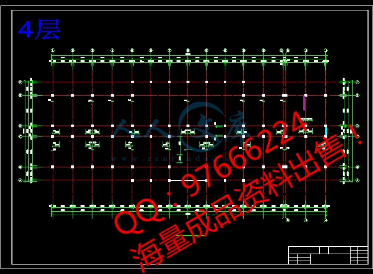
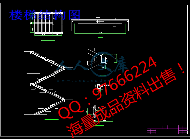
立面、卫生间.dwg
立面、卫生间.dwg

[T0017]五层5880平米教学楼(计算书、建筑、结构图)

收藏

资源目录
跳过导航链接。
压缩包内文档预览:
预览图
编号:443722    类型:共享资源    大小:2.75MB    格式:ZIP    上传时间:2015-06-25 上传人:小*** IP属地:福建
50
积分
关 键 词:
t0017 平米 教学楼 计算 建筑 结构图
资源描述:

摘   要

建筑地点:阳泉开发区               construction Site: YangQuan

结构形式:框架结构                 construction Systen:  Frame structure

建筑面积:5880 m2                  floor Area: 5880m2        

层数/高度:5层/21m               stories/Height: 5stories/21 m

主要用途:教学 、办公              main Use: teaching、office

框架结构                           frame structure

现浇混凝土                         cast-in-place  concreate  

条形基础                           spread  footings

屋面板                             roof  plate

正截面                             normal  section

根据教学要求入手,从“灵活使用”的角度出发,绿化与建筑相结合,改善外部购物环境。内部采用大、中、小不同的空间尺寸以及斜线、曲线等不同的要素,构成了富于层次流动感强的浓郁的气氛。

综合楼是一座以教学为主的集办公、娱乐等功能的建筑物。在设计理念上,力求在整体造型上突出现代、新颖、做到简洁、明快、虚实相接、刚柔相济、给人以蓬勃向上的感觉。设计上采用拉索点式玻璃幕墙等新技术、新材料,创造一个满足功能、符合环境、有鲜明现代性的建筑形象。透过通透落地玻璃幕墙,使室内、室外空间相互交融,同时作为窗口,起到了一定的美化市容的作用。

"Flexible use"and combination of greening and building latgely improve its outside shopping environment.In the inside,laige,medium and small--sized spice,togethei with the various building elemenrs like diagonal and curve,creates a dense atmosphere.Xin'Plaza conveys the traditional charm of modern architecture,and effectively billboatd.

Geri Plaza is an integrated including shopping,restaurants,entertainment cente and offices.In terms of design concept,the designers tried to fully materialize both the general features offirst-class modem shopping mall and the unique identity of FriendshipShopping Mall.In terms of overall form,this shopping mall gives priority to modernism and novelty ---its concise and lively shape conveys a sense of vigor and aggression.Steel strure,aluminum plate outerdecoration and suspended cable point glass curtain wall and other mew technique and materials are introduced into thedesign,giving prominence to the characteristic of steel structure.The harmonious combination of steel,glass and aluminum pate creates an idantity of modem atchitecture that can not only meetthe functional requirements but also assort with the envuribnebt.The transparentfloor glass curtain wall makes the outdoor and indoor space meet.And it is also a window,showing the passersby the indoor scenery of the shopping mall.


第一部分  建筑设计说明

1  建筑概况

1.1  工程简介

1.1.1  设计题目:阳泉学院综合楼

1.1.2  设计依据:本工程系根据阳泉市规划部门批准之方案和有关《建筑设计规范》进行设计的。

1.1.3  设计要求:建筑耐久年限二级(50年),耐火等级二级,抗震设防为7度。

1.1.4  建筑地点及地基平面图:

本建筑位于阳泉市开发区,场地地形平坦。其拟建基地平面图见附图


1  建筑场地


1.1.5  结构形式:框架结构

1.1.6  建筑规模:

  本建筑为五层、三跨框架结构。建筑面积大约为5880mm2,其中教室面积大约为1800mm2,办公区面积大约为400mm2,实验室面积大约为1000mm2,其他房屋面积大约为1000mm2,层高为4.2m;

1.2  建筑技术条件资料

1.2.1  气象条件:

基本风压0.40KN/m2   基本雪压0.35KN/m2。

1.2.2  工程地质条件(见设计任务书)

1.3  建筑方案简要说明

1.3.1  朝向:

  教学楼就是为学生提供正常教学的场所空间。由于它的功能要求,空间特征及交通组织等,故此建筑选择坐北朝南的朝向。

1.3.2  本楼各层均采用自然排风。

1.3.3  采用自然和人工采光相结合的方式。

1.3.4  开间模数:

  根据我国自己的实践建议采用三种开间模数,即3M.采用这相关模数的优点有三:

①能满足商场购物的正常要求,与工业化生产紧密结合,

②考虑结构的互换性,有利于预制构件的大量生产

③与我国统一的标准窗扇采用0.3m为倍数尺度结合起来,故本建筑采用建筑模数为3m。

1.3.5  进深: 采用6.9m进深,能够满足教学的要求。

1.3.6  层高: 根据资料层高取4.2 m。

1.3.7  顶棚: 均采用粉底。

1.3.8  地面:教学楼地面均采用水磨石做法。

1.3.9  墙体: 采用加气混凝土空心砌块,内外墙厚均为250厚,对于小于500的墙垛用粘土砖砌。

1.3.10  安全疏散和防火分区:

    本建筑要求耐火等级为Ⅱ级,《规范》要求防火分区间 的最大允许面积为1000mm2,每层设一个防火分区每层最大面积864mm2,均符合防火要求。对房间超过60mm2以上的均设置两个以上的门。各层均设消防栓。底层开一个大门,楼内设有两部楼梯,以满足人流的疏散与防火要求。

1.3.11  走廊宽度

   决定宽度的因素包括交通量、建筑物长度及门的开启方向,为防止突发性火灾或减少火灾危害程度,人流量较大,故取2.4m宽度。

1.4  建筑物的优缺点

    本建筑根据不同要求做了不同的设计布置与处理。对防震、通风、采光等都做了具体的设计安排。对人流的疏散、防火、照明、等都做了比较合理的布置,总的来说是合理的。


内容简介:
毕业设计(论文)说明书摘 要建筑地点:阳泉开发区 construction Site: YangQuan结构形式:框架结构 construction Systen: Frame structure建筑面积:5880 m2 floor Area: 5880m2 层数/高度:5层/21m stories/Height: 5stories/21 m主要用途:教学 、办公 main Use: teaching、office框架结构 frame structure现浇混凝土 cast-in-place concreate 条形基础 spread footings屋面板 roof plate正截面 normal section根据教学要求入手,从“灵活使用”的角度出发,绿化与建筑相结合,改善外部购物环境。内部采用大、中、小不同的空间尺寸以及斜线、曲线等不同的要素,构成了富于层次流动感强的浓郁的气氛。综合楼是一座以教学为主的集办公、娱乐等功能的建筑物。在设计理念上,力求在整体造型上突出现代、新颖、做到简洁、明快、虚实相接、刚柔相济、给人以蓬勃向上的感觉。设计上采用拉索点式玻璃幕墙等新技术、新材料,创造一个满足功能、符合环境、有鲜明现代性的建筑形象。透过通透落地玻璃幕墙,使室内、室外空间相互交融,同时作为窗口,起到了一定的美化市容的作用。Flexible useand combination of greening and building latgely improve its outside shopping environment.In the inside,laige,medium and small-sized spice,togethei with the various building elemenrs like diagonal and curve,creates a dense atmosphere.XinPlaza conveys the traditional charm of modern architecture,and effectively billboatd.Geri Plaza is an integrated including shopping,restaurants,entertainment cente and offices.In terms of design concept,the designers tried to fully materialize both the general features offirst-class modem shopping mall and the unique identity of FriendshipShopping Mall.In terms of overall form,this shopping mall gives priority to modernism and novelty -its concise and lively shape conveys a sense of vigor and aggression.Steel strure,aluminum plate outerdecoration and suspended cable point glass curtain wall and other mew technique and materials are introduced into thedesign,giving prominence to the characteristic of steel structure.The harmonious combination of steel,glass and aluminum pate creates an idantity of modem atchitecture that can not only meetthe functional requirements but also assort with the envuribnebt.The transparentfloor glass curtain wall makes the outdoor and indoor space meet.And it is also a window,showing the passersby the indoor scenery of the shopping mall.第一部分 建筑设计说明1 建筑概况1.1 工程简介1.1.1 设计题目:阳泉学院综合楼 1.1.2 设计依据:本工程系根据阳泉市规划部门批准之方案和有关建筑设计规范进行设计的。 1.1.3 设计要求:建筑耐久年限二级(50年),耐火等级二级,抗震设防为7度。1.1.4 建筑地点及地基平面图:本建筑位于阳泉市开发区,场地地形平坦。其拟建基地平面图见附图 图1 建筑场地1.1.5 结构形式:框架结构1.1.6 建筑规模: 本建筑为五层、三跨框架结构。建筑面积大约为5880mm2,其中教室面积大约为1800mm2,办公区面积大约为400mm2,实验室面积大约为1000mm2,其他房屋面积大约为1000mm2,层高为4.2m; 1.2 建筑技术条件资料1.2.1 气象条件:基本风压0.40KN/m2 基本雪压0.35KN/m2。1.2.2 工程地质条件(见设计任务书)1.3 建筑方案简要说明1.3.1 朝向: 教学楼就是为学生提供正常教学的场所空间。由于它的功能要求,空间特征及交通组织等,故此建筑选择坐北朝南的朝向。1.3.2 本楼各层均采用自然排风。1.3.3 采用自然和人工采光相结合的方式。1.3.4 开间模数: 根据我国自己的实践建议采用三种开间模数,即3M.采用这相关模数的优点有三:能满足商场购物的正常要求,与工业化生产紧密结合,考虑结构的互换性,有利于预制构件的大量生产与我国统一的标准窗扇采用0.3m为倍数尺度结合起来,故本建筑采用建筑模数为3m。1.3.5 进深: 采用6.9m进深,能够满足教学的要求。1.3.6 层高: 根据资料层高取4.2 m。1.3.7 顶棚: 均采用粉底。1.3.8 地面:教学楼地面均采用水磨石做法。1.3.9 墙体: 采用加气混凝土空心砌块,内外墙厚均为250厚,对于小于500的墙垛用粘土砖砌。1.3.10 安全疏散和防火分区: 本建筑要求耐火等级为级,规范要求防火分区间 的最大允许面积为1000mm2,每层设一个防火分区每层最大面积864mm2,均符合防火要求。对房间超过60mm2以上的均设置两个以上的门。各层均设消防栓。底层开一个大门,楼内设有两部楼梯,以满足人流的疏散与防火要求。1.3.11 走廊宽度 决定宽度的因素包括交通量、建筑物长度及门的开启方向,为防止突发性火灾或减少火灾危害程度,人流量较大,故取2.4m宽度。1.4 建筑物的优缺点 本建筑根据不同要求做了不同的设计布置与处理。对防震、通风、采光等都做了具体的设计安排。对人流的疏散、防火、照明、等都做了比较合理的布置,总的来说是合理的。第二部分结构设计说明1 结构方案确定说明1.1 建设项目名称:太工阳泉学院1.1.1 建筑介绍:建筑面积为5880,综合楼为五层钢筋混凝土框架结构体系,楼盖及屋盖均采用现浇钢筋混凝土框架结构,楼板厚度采用120,填充墙采用蒸压粉煤灰加气混凝土砌块。1.1.2 优缺点:主要优点:结构整体性好,建筑布置灵活性大,能满足使用要求高,功能复杂,有抗震要求的高层建筑的要求。本建筑梁、柱、屋面板、楼面板全为现浇,以便房间灵活布置和施工方便(预留孔洞)。主要缺点:现场工作量大,模板耗用量大。1.2 设计资料:1.2.1 基本参数:气象条件: 基本风压0.40KN/m2 基本雪压0.35KN/m2。工程地质条件:根据对建筑基地的勘察结果,地质情况见表1建筑地点冰冻深度:-0.7米;建筑场地类别:II类场地土;地震设防烈度:7度。表1 建筑地层一览表序号岩土分类土层描述土层深度(m)厚度范围(m)地基承载力(KPa)压缩模量(MPa)1杂填土由砖块、碎石、粘性土等组成、松散1.01.21.11.52粉质粘土黄褐色、湿、可塑2.02.41.51.82005.03中、粗砂黄褐色、石英长石质、混粒结构、稍湿3.64.31.82.13009.54砾砂4.815.035021.0注:表中所给土层深度由自然地坪算起。1.2.2 楼地面做法:屋面做法:三毡四油绿豆砂20厚水泥砂浆找平层50厚聚苯乙烯泡沫塑料板保温层20厚水泥砂浆找平层平均厚度120厚矿渣找坡层120厚钢筋混凝土板20厚板底抹灰楼面做法:30厚水磨石地面120厚钢筋混凝土板20厚板底抹灰1.2.3 材料:梁柱强度等级为C30,受力筋采用HPB335。箍筋采用HPB235,分布筋采用HPB235级钢筋。本建筑楼盖按弹性方案考虑L1/L22按双向板设计,本建筑楼盖全部采用混凝土强度等级为C30现浇双向板且设次梁。本建筑柱网尺寸为4.5m6.9m。1.3 设计内容(1) 确定梁柱截面尺寸及框架计算简图;(2) 荷载计算;(3) 框架横向侧移计算;(4) 框架在水平及竖向力作用下的内力分析;(5) 内力组合及截面设计;(6) 板的计算;(7) 楼梯的计算;(8) 雨篷的计算;(9) 基础的计算。第三部分毕业设计任务书一、设计题目阳泉学院综合楼二、建筑地点及拟建基地平面图本建筑位于阳泉市开发区。由主管批准拟建基地平面图见图1。三、建筑面积和层数建筑面积45005000平方米左右;层数56层;层高3.94.2m。四、结构形式框架结构五、设计任务1、建筑设计部分使用要求教室(60m2)18间,大教室(120m2 )6间;试验室(90m2)10间,准备室(30m2)10间;办公室(30m2)10间,会议室(60m2)6间;其它房间自行安排。 设计内容建筑方案及其初步设计;建筑物平面、立面和剖面设计;主要部位的建筑构造设计及材料作法;绘制建筑施工图。成果形式建筑设计说明书和建筑施工图。施工图包括:建筑设计说明,总平面图(比例1:500);首层平面图、二层五层平面图(任选其中二层)、正立面图、侧立面图不少于2个(比例1:100);剖面图2个(比例1:100);主外墙大样图1个,节点大样图34个,(比例1:10或1:20)。2、结构设计部分内容要求确定结构方案:上部承重结构方案与布置;楼(屋)盖结构方案与布置;基础方案布置;结构措施及其特殊部位的处理等。结构设计计算完成结构设计计算书一份(统一用纸),内容包括:荷载汇集;地震作用计算;风荷载计算;荷载组合及内力分析;一榀框架计算;现浇板计算;楼梯计算;悬挑构件计算;基础及基础梁计算;会议室(楼)屋盖计算;其它必要的构件计算。成果形式结构设计说明书,结构设计计算书,结构施工图。施工图包括:结构设计说明;基础剖平面布置图,比例1:100;基础详图,比例1:301:50;结构布置图及配筋图,比例1:100,15层任选其一;一榀框架配筋图,比例1:301:50;楼梯配筋图,比例1:301:50;其它必要的构件配筋图,如:雨蓬或挑梁,比例1:301:50。3、毕业设计成果总汇设计说明书一份(采用统一稿纸,并由打印机输出),内容包括:中外文摘要(600字左右)建筑、结构设计说明书(30004000字,含图表)结构设计计算书(约2万字)列出参考资料和文献外文资料翻译5000左右字(要求与建筑工程相关的资料,可自选,但需要指导教师确认)。设计图纸部分绘制图纸:图纸规格A1(白图),1214张。可部分为计算机(CAD)绘图。六、建筑技术条件1、气象条件 基本风压0.40KN/m2 基本雪压0.35KN/m2。2、工程地质条件根据对建筑基地的勘察结果,地质情况见表1建筑地点冰冻深度:-0.7米;建筑场地类别:II类场地土;地震设防烈度:7度。表1 建筑地层一览表序号岩土分类土层描述土层深度(m)厚度范围(m)地基承载力(KPa)压缩模量(MPa)1杂填土由砖块、碎石、粘性土等组成、松散1.01.21.11.52粉质粘土黄褐色、湿、可塑2.02.41.51.82005.03中、粗砂黄褐色、石英长石质、混粒结构、稍湿3.64.31.82.13009.54砾砂4.815.035021.0注:表中所给土层深度由自然地坪算起。3、各种用房的活荷载标准值见现行建筑结构荷载规范。七、时间安排八、参考资料1、国家标准、规范、规程总图制图标准(GB/T50103-2001)建筑制图标准(GB/T50104-2001)建筑结构制图标准(GB/T50105-2001)教学楼建筑设计规范(JBJ/67-89)建筑设计防火规范(GBJ/6-87)民用建筑设计通则(JGJ/37-87)建筑结构荷载规范(GB50009-2001)混凝土结构设计规范(GB50010-2002)建筑地基基础设计规范(GB50007-2002)建筑抗震设计规范(GB50011-2001)2、参考书教科书建筑设计资料集(13)钢筋混凝土设计手册建筑结构静力计算手册建筑结构构造资料集(上、下册)山西省建筑、结构通用图集第四部分结构设计计算1 工程概况:1.1 柱网与层高:本办公楼采用内廊式小柱网,边跨为6.9m,中间跨为2.4m,层高取4.2m,如下图所示:柱网布置图 1.2 框架结构承重方案的选择:竖向荷载的传力途径:楼板的均布活载和恒载经次梁间接或直接传至主梁,再由主梁传至框架柱,最后传至地基。根据以上楼盖的平面布置及竖向荷载的传力途径,本办公楼框架的承重方案为横向框架承重方案,这可使横向框架梁的截面高度大,增加框架的横向侧移刚度。 框架结构的计算简图横向框架组成的空间结构1.3 梁、柱截面尺寸的初步确定:1.3.1 梁截面高度:梁截面高度一般取梁跨度的1/12至1/8。本方案取L1、L4取bh=250500 L2、L3、L6取bh=300600L5取bh=300850L7取bh=300800L8、L9取bh=3006001.3.2 柱的截面尺寸:框架柱的截面尺寸根据柱的轴压比限值,按下列公式计算: (1)柱组合的轴压力设计值N=Fg E n注:考虑地震作用组合后柱轴压力增大系数。F按简支状态计算柱的负载面积。g E 折算在单位建筑面积上的重力荷载代表值,可近似的取14KN/m2。n为验算截面以上的楼层层数。(2)AcN/uNfc 注:uN 为框架柱轴压比限值,本方案为二级抗震等级,查抗震规范可知取为0.8。 fc 为混凝土轴心抗压强度设计值,对C30,查得14.3N/mm2。计算过程:对于边柱:N=Fg E n=1.320.79145=1891.89(KN)AcN/uNfc=1891.89103/0.8/14.3=165375(mm2)取700mm700mm对于内柱:N=Fg E n=1.2525.83145=2260.125(KN)AcN/uNfc=2260.125103/0.8/14.3=197563.37(mm2) 取700mm700mm柱截面尺寸(mm)层次混凝土等级bh1-5C307007002 框架侧移刚度的计算2.1 梁柱线刚度的计算2.1.1 横梁线刚度i b的计算:类别Ec(N/mm2)bh(mmmm)I0(mm4)l(mm)EcI0/l(Nmm)1.5EcI0/l(Nmm)2EcI0/l(Nmm)BC跨、DE跨3.01043006005.4010969002.3510103.5310104.701010CD跨3.01043006005.4010924006.75101010.1101013.51010AC跨、DF跨3.01043008501.5010999004.5510106.8310109.101010AB跨、EF跨3.01043006005.4010930005.4010108.10101010.810102.1.2 柱线刚度i c的计算:I=bh3/12层次hc(mm)Ec(N/mm2)bh(mmmm)Ic(mm4)EcIc/hc(Nmm)155003.01047007002.0101010.9110102-542003.01047007002.0101014.2910102.2 各层横向侧移刚度计算: (D值法)a.底层、B-2、B-3、B-4、B-12、E-2、E-3(6根)K=0.431c=(0.5+K)/(2+K)=0.383Di1=c12ic/h2=0.3831210.911010/55002=16576、B-1、B-13、E-1、E-4、E-12、E-13 (6根)K=3.53/10.91=0.324c=(0.5+K)/(2+K)=0.355Di2=c12ic/h2 =0.3551210.911010/55002 =15364、C-1、D-1、C-13、D-13、D-4 、D-5、D-11、D-12(8根)K=(10.13+3.53)/10.91=1.252c=(0.5+K)/(2+K)=0.539Di3=c12ic/h2 =0.5391210.911010/55002 =23328、C-2、D-2、C-3、D-3、C-4、C-5、C-11、C-12、C-7 、C-9(10根)K=(13.5+4.7)/10.91=1.668 c=(0.5+K)/(2+K)=0.591Di4=c12ic/h2 =0.5911210.911010/55002 =25578、B-5、B-11(2根) K=(8.1+4.7)/10.91=1.173c=(0.5+K)/(2+K)=0.527Di5=c12ic/h2 =0.5271210.911010/55002 =22808、A-5、A-11、F-5、F-11 (4根)K=8.1/10.91=0.742c=(0.5+K)/(2+K)=0.453Di6=c12ic/h2 =0.4531210.911010/55002 =19606. E-5、E-11(2根) K=(3.53+8.1)/10.91=1.066c=(0.5+K)/(2+K)=0.511Di7=c12ic/h2 =0.5111210.911010/55002 =22116. F-6、F-7、F-8、F-9、F-10、A-6、A-10(7根)K=9.1/10.91=0.834c=(0.5+K)/(2+K)=0.471Di8=c12ic/h2 =0.4711210.911010/55002 =20385. A-7、A-9(2根) K=10.8/10.91=0.99c=(0.5+K)/(2+K)=0.498Di9=c12ic/h2 =0.4981210.911010/55002 =21553. C-6、C-10、D-6、D-7、D-8、D-9、D-10 (7根)K=(13.5+9.1)/10.91=2.071c=(0.5+K)/(2+K)=0.632Di6=c12ic/h2 =0.6321210.911010/55002 =27353. B-7、B-9 (2根)K=(10.8+4.7)/10.91=1.421c=(0.5+K)/(2+K)=0.562Di6=c12ic/h2 =0.5621210.911010/55002 =24323D1=165766+153646+233288+2557810+228082+196064+221162+203857+215532+273537+243232=1228234b.第二层第五层、B-2、B-3、B-4、B-12、E-2、E-3(6根)K=4.72/(14.292)=0.329c=K/(2+K)=0.141Di1=c12ic/h2 =0.1411214.291010/42002 =13707、B-1、B-13、E-1、E-4、E-12、E-13 (6根)K=3.532/(14.292)=0.247c=K/(2+K)=0.11Di2=c12ic/h2 =0.111214.291010/42002 =10693、C-1、D-1、C-13、D-13、D-4、D-5、D-11、D-12 (8根)K=(10.1+3.53)2/(14.292)=0.956c=K/(2+K)=0.323Di3=c12ic/h2 =0.3231214.291010/42002 =31399、C-2、D-2、C-3、D-3、C-4、C-5、C-11、C-12、 C-7 、C-9(10根)K=(13.5+4.7)/(14.292)=1.274 c=K/(2+K)=0.389Di4=c12ic/h2 =0.3891214.291010/42002 =37815、B-5、B-11(2根)K=(8.1+4.7)2/(14.292)=0.896c=K/(2+K)=0.309Di5=c12ic/h2 =0.3091214.291010/42002 =30038、A-5、A-11、F-5、F-11 (4根)K=8.12/(14.292)=0.567c=K/(2+K)=0.221Di6=c12ic/h2 =0.2211214.291010/42002 =21484、E-5、E-11(2根)K=(3.53+8.1)2/(14.292)=0.814c=K/(2+K)=0.289Di7=c12ic/h2 =0.2891214.291010/42002 =28094、F-6、F-7、F-8、F-9、F-10、A-6、A-10(7根)K=9.12/(14.292)=0.542c=K/(2+K)=0.242Di8=c12ic/h2 =0.2421214.291010/42002 =23525、A-7、A-9(2根)K=10.82/(14.292)=0.756c=K/(2+K)=0.274Di9=c12ic/h2 =0.2741214.291010/42002 =26636. C-6、C-10、D-6、D-7、D-8、D-9、D-10 (7根)K=(13.5+9.1)2/(14.292)=1.582c=K/(2+K)=0.442Di6=c12ic/h2 =0.4421214.291010/42002 =42967. B-7、B-9 (2根)K=(10.8+4.7)2/(14.292)=1.085c=K/(2+K)=0.352Di6=c12ic/h2 =0.3521214.291010/42002 =34218D2=137076+106936+313998+3781510+300382+214844+280942+235257+266362+429677+342182=1565094由此可知,横向框架梁的层间侧移刚度为:层次12345Di(N/mm)12282341565094156509415650941565094D1/D2=1228234/15650940.7,故该框架为规则框架。3 重力荷载代表值的计算3.1 资料准备:查荷载规范可取:、 屋面永久荷载标准值(不上人)三毡四油绿豆砂 0.4 KN/m220厚水泥砂浆找平层 200.02=0.4 KN/m250厚聚苯乙烯泡沫塑料板保温层 0.050.5=0.025 KN/m220厚水泥砂浆找平层 200.02=0.4 KN/m2平均厚度120厚矿渣找坡层 0.128=0.96 KN/m2120厚钢筋混凝土板 250.12=3.0 KN/m220厚板底抹灰 170.02=0.34 KN/m2合计 5.35 KN/m2、1-4层楼面均布恒载:30厚水磨石地面 0.65 KN/m2120厚钢筋混凝土板 250.12=3.0 KN/m220厚板底抹灰 170.02=0.34KN/m2 合计 3.99 KN/m2、屋面及楼面可变荷载标准值:不上人屋面均布活荷载标准值 0.7 KN/m2楼面活荷载标准值 2.0 KN/m2屋面雪荷载标准值 0.35 KN/m2、梁柱密度25 KN/m2蒸压粉煤灰加气混凝土砌块 5.5KN/m33.2 重力荷载代表值的计算:3.2.1 第一层:(1)、梁、柱重量:类别净 跨(mm)截 面(mm)密 度(KN/m3)体 积(m3)数 量(根)单 重(KN)总 重(KN)横梁6200300600251.1161927.9530.101700300600250.306137.6599.459200300850252.346758.65410.552300300600250.414710.3572.45纵梁3800250500250.4752411.88285.123500250500250.4382010.95219.007700300800251.848346.20138.60类别计算高度(mm)截 面(mm)密 度(KN/m3)体 积(m3)数 量(根)单 重(KN)总 重(KN)柱4200700700252.0585651.452881.2(2)、内外填充墙重的计算: 横墙: BC跨、DE跨墙:墙厚250mm,计算长度6200mm,计算高度4200-600=3600mm。 单跨体积:0.256.23.6=5.58m3 单跨重量:5.585.5=30.69KN 数量:13 总重:30.6913=398.97KN CD跨墙:墙厚250mm,计算长度1700mm,计算高度4200-600=3600mm。 单跨体积:(1.73.6-1.72.7)0.25=0.383m3 单跨重量:0.3835.5=2.11KN 数量:2 总重:2.112=4.22KN AB跨、EF跨墙:墙厚250mm,计算长度2300mm,计算高度4200-600=3600mm。 单跨体积:0.252.33.6=2.07m3 单跨重量:2.075.5=11.39KN 数量:6 总重:11.396=68.34KN DF跨墙:墙厚250mm,计算长度9200mm,计算高度4200-850=3350mm。 单跨体积:0.259.23.35=7.71m3 单跨重量:7.715.5=42.41KN 数量:1 总重:42.41KN BC跨墙:墙厚250mm,计算长度6200mm,计算高度4200-600=3600mm。 单跨体积:6.23.60.25=5.58m3 单跨重量:5.585.5=30.69KN 数量:2 总重:30.692=61.38KN 横墙总重:398.97+4.22+68.34+42.41+61.38=575.32KN 纵墙:12跨外墙:单个体积:(3.83.7)-(2.73.8) 0.25=0.95m3数量:10 总重:0.95105.5=52.25KN 56跨外墙:单个体积:(3.83.7)-(3.52.7) 0.25=0.875m3数量:10 总重:0.875105.5=48.125KN 厕所纵墙:体积:(3.83.7-12.1)0.25=2.99 m3数量:2 总重:2.9925.5=32.89KN 楼梯间外纵墙:体积:(3.53.0-1.82.1)0.25=2.375 m3数量:2 总重:2.37525.5=26.125KN12跨内纵墙:单个体积:(3.83.7)-(12.1) 0.25=2.99m3数量:8 总重:2.9985.5=131.56KN 56跨内纵墙:单个体积:(3.53.7)-(12.1) 0.25=2.713m3数量:6 总重:2.71365.5=89.53KN56跨内纵墙:单个体积:(3.83.7)0.25=3.238m3数量:4 总重:3.23845.5=71.236KN 纵墙总重:52.25+48.125+32.89+26.125+131.56+89.53+71.236=451.72KN(3)、窗户计算(钢框玻璃窗): C-1:尺寸:3800mm2700mm 自重:0.4KN/m2 数量:10 重量:3.82.70.410=41.04KN C-2:尺寸:1700mm2700mm 自重:0.4KN/m2 数量:1重量:1.72.70.41=1.836KN C-3:尺寸:3500mm2700mm 自重:0.4KN/m2 数量:10 重量:3.52.70.410=37.8KN C-4:尺寸:3800mm1200mm 自重:0.4KN/m2 数量:2重量:3.81.20.42=3.648KN总重:41.04+1.836+37.8+3.648=84.324KN(4)、门重计算: 木门:M-1:尺寸:1000mm2100mm 自重:0.15KN/m2 数量:16 重量:1.02.10.1516=5.04KN M-2:尺寸:900mm2100mm 自重:0.15KN/m2 数量:2重量:0.92.10.152=0.567KN M-3:尺寸:7700mm3000mm 自重:0.4KN/m2 数量:1重量:7.730.41=9.24KN总重:5.04+0.567+9.24=14.847KN(5)、楼板恒载、活载计算(楼梯间按楼板计算): 面积:263.315+507.275+130.6=901.19(m2) 恒载:3.99901.19=3595.7481KN 活载:2.0901.19=1802.38KN由以上计算可知,一层重力荷载代表值为G1=G 恒+0.5G活=(530.1+99.45+410.55+72.45)1.05+(285.12+219+138.6)1.05+28811.05+575.32+451.72+84.324+14.847+(3595.7481+1802.3)0.5 =10491.4426KN注:梁柱剩上粉刷层重力荷载而对其重力荷载的增大系数1.05。3.2.2 第二层第四层(1)、比较其与第一层的异同,只有A79和C79不同,可得到二到四层重力荷载代表值为G=10491.4426+12.898+33.11-9.24-61.38+25.492=10517.81063.2.3 第五层顶端重力荷载代表值的计算:横梁:530.1+99.45+410.55+72.45=1112.55KN纵梁:285.12+219+138.6=642.72KN柱:0.70.72.12556=1440.6KN横墙:(575.32-61.38+50.98-30.69-11.39+74.36)/2=298.6KN纵墙:(451.72+33.11+12.898)/2=248.864KN 女儿墙体积:0.60.25(36+16.9+18+25.2+12)+1.50.2525.34=25.718m3女儿墙重量:25.71818=462.924KN门重:门高2100,计算高度为门的2100以上,故系数为0,则木门重为0。 窗重:(84.324+6.72)/2=45.522KN DF 跨7、9内横墙:单跨体积:(9.23.35-1.82.1)0.25=6.76m3数量:2 总重:6.7625.5=74.36KN 楼板恒载、活载计算: 恒载:901.195.525=4979.0748KN 活载:901.190.7=630.833KN雪载:901.190.35=315.4165KN由以上计算可知,顶端重力荷载代表值为G顶=G 恒+0.5G活=(1112.55+642.72+1440.6)1.05+298.6+248.864+45.522+4979.0748+462.924+(630.833+315.4165)0.5 =9863.7731KN集中于各楼层标高处的重力荷载代表值G i的计算结果如下图所示:4 横向水平地震荷载作用下框架结构的内力和侧移计算4.1 横向自振周期的计算:横向自振周期的计算采用结构顶点的假想位移法。基本自振周期T1(s)可按下式计算:T1=1.7T (uT)1/2注:uT假想把集中在各层楼面处的重力荷载代表值Gi作为水平荷载而算得的结构顶点位移。T结构基本自振周期考虑非承重砖墙影响的折减系数,取0.6。uT按以下公式计算:VGi=Gk(u)i= VGi/D ij uT=(u)k注:D ij 为第i层的层间侧移刚度。 (u)i为第i层的层间侧移。 (u)k为第k层的层间侧移。 s为同层内框架柱的总数。结构顶点的假想侧移计算层次Gi(KN)VGi(KN)D i(N/mm)ui(mm)ui(mm)59863.77319863.773115650946.302107.794410517.810620381.5837156509413.023101.492310517.810630899.3943156509419.74388.469210517.810641417.2049156509426.46368.726110491.442651908.6475122823442.26342.63T1=1.7T (uT)1/2 =1.70.6(0.107794)1/2=0.335(s)4.2 水平地震作用及楼层地震剪力的计算:本结构高度不超过40m,质量和刚度沿高度分布比较均匀,变形以剪切型为主,故可用底部剪力法计算水平地震作用,即:(1)、结构等效总重力荷载代表值GeqGeq=0.85Gi=0.85(10491.4426+10517.81063+9863.7731)=44122.3504(KN) (2)、计算水平地震影响系数1查表得二类场地近震特征周期值Tg=0.35s。查表得设防烈度为7度的max=0.081=max=0.08 (3)、结构总的水平地震作用标准值FEkFEk=1Geq =0.0844122.3504 =3529.788(KN)因1.4Tg=1.40.35=0.49s T1=0.335s,所以不考虑顶部附加水平地震作用。 各质点横向水平地震作用按下式计算: Fi=GiHiFEk(1-n)/(GkHk)地震作用下各楼层水平地震层间剪力Vi为 Vi=Fk(i=1,2,n)计算过程如下表:各质点横向水平地震作用及楼层地震剪力计算表层次Hi(m)Gi(KN)GiHi(KNm)GiHi/GjHjFi(KN)Vi(KN)522.39863.7731219962.140.3071083.64491083.645418.110517.8106190372.370.266938.9242022.569313.910517.8106146197.570.204720.0772742.64629.710517.8106102022.760.142501.233243.87615.510491.442657702.930.081285.9133529.789716257.77各质点水平地震作用及楼层地震剪力沿房屋高度的分布见下图:(具体数值见上表)4.3 多遇水平地震作用下的位移验算:水平地震作用下框架结构的层间位移(u)i和顶点位移u i分别按下列公式计算:(u)i = Vi/D iju i=(u)k各层的层间弹性位移角e=(u)i/hi,根据抗震规范,考虑砖填充墙抗侧力作用的框架,层间弹性位移角限值e1/550。计算过程如下表: 横向水平地震作用下的位移验算层次Vi(KN)D i(N/mm)(u)i (mm)ui(mm)hi(mm)e=(u)i /hi51083.64515650940.6928.68342001/606942022.56915650941.2927.99142001/325132742.64615650941.7526.69942001/239723243.87615650942.0734.94742001/202613529.78912282342.8742.87455001/1914由此可见,最大层间弹性位移角发生在第一层,1/19141/550,满足规范要求。4.4 水平地震作用下框架内力计算:4.4.1框架柱端剪力及弯矩的计算:框架柱端剪力及弯矩分别按下列公式计算:Vij=DijV i /DijM bij=Vijyh M uij=Vij(1-y)hy=yn+y1+y2+y3注:yn框架柱的标准反弯点高度比。 y1为上下层梁线刚度变化时反弯点高度比的修正值。 y2、y3为上下层层高变化时反弯点高度比的修正值。 y框架柱的反弯点高度比。底层柱需考虑修正值y2,第二层柱需考虑修正值y1和y3,其它柱均无修正。下面以轴线横向框架内力的计算为例:各层柱端弯矩及剪力计算(边柱)层次hi(m)Vi(KN)D ij(N/mm)边 柱Di1(N/mm)Vi1(KN)ky(m)M bi1(KNm)M ui1(KNm)54.21083.6451565094137079.490.3290.2158.5531.3144.22022.56915650941370717.7140.3290.3526.0448.3634.22742.64615650941370724.020.3290.4545.455.4924.23243.87615650941370728.410.3290.50660.3858.9515.53529.78912282341657647.6370.4310.771202.060.00各层柱端弯矩及剪力计算(中柱)层次hi(m)Vi(KN)D ij(N/mm)中 柱Di2(N/mm)Vi2(KN)kY(m)M bi2(KNm)M ui2(KNm)54.21083.64515650943781526.1821.2740.3639.5970.3844.22022.56915650943781548.8681.2740.4592.36112.8934.22742.64615650943781566.2661.2740.46128.03150.2924.23243.87615650943781578.3771.2740.50164.59164.5915.53529.78912282342557873.5081.6680.65262.79141.504.4.2 梁端弯矩、剪力及柱轴力的计算:梁端弯矩、剪力及柱轴力分别按以下公式计算: M l b=i l b(Mbi+1,j + M u i,j)/(i l b+ i r b) M r b=i r b(Mbi+1,j + M u i,j)/(i l b+ i r b) V b=(M l b+ M r b)/ l Ni=(V l b- V r b)k 具体计算过程见下表:梁端弯矩、剪力及柱轴力的计算层次边梁走道梁柱轴力MlbMrblVbMlbMrblVb边柱N中柱N531.3118.186.907.1752.2052.202.4043.50-7.17-36.33456.9139.386.9013.96113.1113.12.4094.25-21.13-116.62381.5362.666.9020.90179.99179.992.40149.99-42.03-245.712104.3575.576.9026.08217.05217.052.40180.88-68.11-400.511120.3879.056.9028.90227.04227.042.40189.20-97.01-560.81 轴线横向框架弯矩图(KNm) 轴线横向框架梁剪力图(KN) 轴线横向框架柱轴力图(KN)5 横向水平风荷载作用下框架结构的内力和侧移计算5.1 水平风荷载的计算基本风压0 =0.4KN/m2 ,风荷载体型变化系数,由荷载规范第7.3节查得S =0.8-(-0.5)=1.3。本建筑属于B类地区,H/B=22.3/22.9=0.97荷载规范规定,高度不大于1.5的房屋结构,不考虑风压脉动的影响。 层次12345离地面高度(m)z5.59.713.918.122.3风压高度系数Z0.820.991.111.211.29 在内力分析时,可以将沿框架柱的分布风荷载进一步简化为作用于框架节点的水平集中风荷载。5层: FW5K=1.820.44.5(1.30.6+1.29)4.2=20.3KN4层: FW4K=0.910.44.5(1.29+1.21)4.2=17.2KN3层: FW3K=0.910.44.5(1.21+1.11)4.2=15.96KN2层: FW2K=0.910.44.5(1.11+0.99)4.2=14.45KN1层: FW1K=0.910.44.5(0.994.2+0.825.5)=14.2 KN5.2 风荷载作用下的水平位移验算:根据图1所示的水平荷载,算出层间剪力,然后求出3轴线框架的层间侧移刚度,再分别计算出各层的相对侧移和绝对侧移。计算过程见表1风荷载作用下框架层间剪力及侧移计算层次12345Fi / KN14.214.4515.9617.2020.30Vi / KN82.1167.9153.4637.5020.30D84308103044103044103044103044Ui/0.970.660.520.360.20Ui/0.971.632.152.512.71Ui /hi1/56701/63641/80771/116671/21000由此可见,最大层间弹性位移角发生在第一层,1/19140,x=(VA+alq2/2)/(q1+q2)=(137.48+2.2526.95/2)/(11.01+26.95)=4.42m6.9 m Mmax=252.72+137.484.42-(11.01+26.95) 2.442 /2+26.952.25(4.42-2.25/3)/2=600.85KNm REMmax=0.75600.85=450.64 KNm 其它跨间的最大弯矩计算结果见下表: 跨间最大弯矩计算结果表层次12345跨度BCCDBCCDBCCDBCCDBCCDMmax450.64208.2426.79200.86382.85164.58333.26100.14264.7434.866.4.2 梁端剪力的调整:剪力调整方法同上,结果见各层梁的内力组合和梁端剪力调整表。6.5 框架柱的内力组合:取每层柱顶和柱底两个控制截面,组合结果如下表: 横向框架A柱弯矩和轴力组合 85 41层次截面内力SGK调幅后SQK调幅后SWK(1)SEK(1)S风效应组合S地震效应组合1.35SGK+1.0SQK1.2SGK+1.4SQK|Mmax|M太原理工大学阳泉学院毕业设计(论文) 说明书M1212NNminNmax5柱顶M73.96 8.88 8.91 31.31 88.71 111.17 38.35 99.40 108.73 101.18 111.17 36.04 108.73 N127.80 10.78 2.04 7.17 164.37 169.51 110.48 124.46 183.31 168.45 169.51 110.48 183.31 柱底M-48.24 -11.42 2.43 8.55 -69.22 -75.34 -39.77 -56.45 -76.54 -73.88 76.54 -35.08 -76.54 N181.82 10.78 2.04 7.17 229.20 234.34 159.10 173.08 256.24 233.28 256.24 159.10 256.24 4柱顶M34.01 13.59 13.62 48.36 40.77 75.10 -10.43 83.88 59.50 59.84 83.88 -10.43 59.50 N299.21 41.70 5.98 21.13 404.06 419.13 267.45 308.66 445.63 417.43 308.66 267.45 445.63 柱底M-40.11 -12.66 7.34 26.04 -54.84 -73.33 -16.41 -67.19 -66.81 -65.86 73.33 -16.41 -66.81 N353.23 41.70 5.98 21.13 468.88 483.95 316.07 357.27 518.56 482.26 483.95 316.07 518.56 3柱顶M40.11 12.66 16.42 55.49 43.39 84.77 -13.13 102.29 66.81 65.86 102.29 -13.13 66.81 N470.47 72.63 12.06 42.03 640.88 671.27 442.80 530.22 707.76 666.25 530.22 442.80 707.76 柱底M-39.22 -12.39 13.44 45.40 -45.74 -79.61 3.62 -90.81 -65.34 -64.41 90.81 3.62 -65.34 N524.49 72.63 12.06 42.03 705.71 736.10 494.66 582.08 780.69 731.07 582.08 494.66 780.69 2柱顶M41.27 13.03 18.74 58.95 42.33 89.55 -15.43 107.18 68.74 67.77 107.18 -15.43 68.74 N641.75 103.57 20.10 68.11 875.27 925.92 594.96 736.63 969.93 915.10 736.63 594.96 969.93 柱底M-51.40 -16.21 19.19 60.38 -57.93 -106.28 5.67 -119.92 -85.60 -84.37 119.92 5.67 -85.60 N695.77 103.57 20.10 68.11 940.10 990.75 646.82 788.49 1042.86 979.92 788.49 646.82 1042.86 1柱顶M25.59 8.07 20.33 60.00 15.26 66.49 -33.96 90.84 42.62 42.01 90.84 -33.96 42.62 N812.78 134.43 29.58 97.01 1107.45 1181.99 743.90 945.69 1231.68 1163.54 945.69 743.90 1231.68 柱底M-12.80 -4.04 68.44 202.00 -106.68 65.78 195.85 -224.31 -21.32 -21.02 224.31 195.85 -21.32 N883.52 134.43 29.58 97.01 1192.34 1266.88 811.82 1013.60 1327.18 1248.43 1013.60 811.82 1327.18 注:表中M以左侧受拉为正,单位为kNm,N以受压为正,单位为kN。42 层次截面内力SGK调幅后SQK调幅后SWK(1)SEK(1)S风效应组合S地震效应组合1.35SGK+1.0SQK1.2SGK+1.4SQK|Mmax|M太原理工大学阳泉学院毕业设计(论文) 说明书M1212NNminNmax5柱顶M-54.19 -6.95 20.03 70.38 -99.02 -48.55 -119.37 17.87 -80.11 -74.76 119.37 -117.39 -80.11 N153.54 14.73 10.34 36.33 189.78 215.84 106.05 176.90 222.01 204.87 102.76 106.05 222.01 柱底M36.79 8.87 11.26 39.59 69.51 41.14 75.38 -1.82 58.54 56.57 75.38 71.71 58.54 N207.56 14.73 10.34 36.33 254.60 280.66 154.67 225.52 294.94 269.69 151.38 154.67 294.94 4柱顶M-28.22 -10.75 31.79 112.89 -87.46 -7.35 -140.30 79.83 -48.85 -48.91 140.30 -140.30 -7.35 N362.94 56.73 33.01 116.62 465.42 548.60 238.47 465.88 546.70 514.95 238.47 238.47 548.60 柱底M31.28 10.08 26.01 92.36 83.01 17.46 130.92 -61.19 52.31 51.65 130.92 130.92 52.31 N416.96 56.73 33.01 116.62 530.24 613.42 306.23 548.80 619.63 579.77 306.23 306.23 619.63 3柱顶M-31.28 -10.08 44.50 150.29 -106.31 5.83 -191.17 121.43 -52.31 -51.65 191.17 -191.17 5.83 N572.49 98.72 70.51 245.71 722.53 900.22 341.44 852.51 871.58 825.20 341.44 341.44 900.22 柱底M30.86 9.94 37.91 128.03 97.32 1.79 167.55 -98.75 51.60 50.95 167.55 167.55 1.79 N626.51 98.72 70.51 245.71 787.36 965.04 393.30 904.37 944.51 890.02 393.30 393.30 965.04 2柱顶M-32.04 -10.32 52.33 164.59 -117.39 14.48 -206.89 135.46 -53.57 -52.90 206.89 -206.89 14.48 N782.02 140.70 118.25 400.51 966.71 1264.70 401.74 1234.81 1196.43 1135.40 401.74 401.74 1264.70 柱底M38.22 12.31 52.33 164.59 127.31 -4.56 213.77 -128.57 63.91 63.10 213.77 213.77 -4.56 N836.04 140.70 118.25 400.51 1031.54 1329.53 453.60 1286.66 1269.35 1200.23 453.60 453.60 1329.53 1柱顶M-19.45 -6.26 47.95 141.50 -91.64 29.19 -168.84 125.48 -32.52 -32.10 168.84 -168.84 29.19 N991.80 182.76 170.75 560.81 1205.29 1635.58 456.61 1623.10 1521.69 1446.02 456.61 456.61 1635.58 柱底M9.73 3.13 89.05 262.79 127.82 -96.58 284.14 -262.46 16.27 16.06 284.14 284.14 -96.58 N1062.54 182.76 170.75 560.81 1290.18 1720.47 524.52 1691.01 1617.19 1530.91 524.52 524.52 1720.47 注:表中M以左侧受拉为正,单位为kNm,N以受压为正,单位为kN。 毕业设计(论文)说明书6.5.1 柱端弯矩设计值的调整:A柱:第5层,按抗震规范,无需调整。第4层,柱顶轴压比uN = N/Ac fc=308.66103/14.3/7002=0.040.15,无需调整。柱底轴压比uN = N/Ac fc=483.95103/14.3/7002=0.070.15,无需调整。第3层,柱顶轴压比uN = N/Ac fc=530.22103/14.3/7002=0.080.15,无需调整。柱底轴压比uN = N/Ac fc=582.08103/14.3/7002=0.080.15,无需调整。第2层,柱顶轴压比uN = N/Ac fc=736.63103/14.3/7002=0.110.15,无需调整。柱底轴压比uN = N/Ac fc=788.49103/14.3/7002=0.110.15,无需调整。第1层,柱顶轴压比uN = N/Ac fc=945.69103/14.3/7002=0.130.15,无需调整。柱底轴压比uN = N/Ac fc=1013.6103/14.3/7002=0.14450.64 KNm属第一类T形截面。下部跨间截面按单筋T形截面计算:s=M/(fcmbf,h02)=450.64106/14.3/2300/5652=0.043=1-(1-2s)1/2=0.044As=fcmbf,h0/fy=0.04414.32300565/300=2725.48 mm2实配钢筋228、325,As=2705 mm2。=2705/300/565=1.6%min=0.2%,满足要求。梁端截面受压区相对高度:=fyAs/(fcmbf,h0)=3002705/14.3/2300/565min=0.2%,又As,/ As =2705/1610=1.680.3,满足梁的抗震构造要求。7.1.2 梁斜截面受剪承载力计算: (1)、验算截面尺寸: hw=h0=565mm hw/b=565/300=1.88V=129040N 可知,截面符合条件。 (2)、验算是否需要计算配置箍筋: 0.42ftbh0=0.421.43300565 =101802N129040N sv= nAsv1/bs=250.3/100/300=0.34%svmin=0.24ft/fyv=0.241.43/210=0.16% 加密区长度取0.9m,非加密区箍筋取8150。箍筋配置,满足构造要求。配筋图如下图所示:其他梁的配筋计算见下表:其它梁的配筋计算见下表:层次截面M(KNm)计算As(mm2)实配As(mm2)(%)配箍1支座B189.5401192225、220(1610)0.95加密区双肢8100,非加密区双肢8150Cl153.070962.7225、220(1610)BC跨间450.640.0442718228、325(2705)1.60支座Cr237.1601492225、220(1610)0.95加密区四肢880非加密区四肢8100CD跨间208.20.0591265228(1232)0.732支座B176.8601112.3225、220(1610)0.95加密区双肢8100非加密区双肢8150Cl151.180950.8225、220(1610)BC跨间426.790.042571.3228、325(2705)1.60支座Cr224.5501412.3225、220(1610)0.95加密区四肢8100非加密区四肢8150CD跨间200.860.061219.5228(1232)1.603支座B154.380970.9222、220(1388)0.82加密区双肢8100非加密区双肢8150Cl141.140887.7222、220(1388)BC跨间382.850.042301.5228、325(2705)1.60支座Cr188.5801186.0222、220(1388)0.82加密区四肢8100非加密区四肢8150CD跨间164.580.05993.9228(1232)0.734支座B136.250856.9220、218(1137)0.67加密区双肢8100非加密区双肢8150Cl132.970836.3220、218(1137)BC跨间333.260.031998.4225、322(2122)1.25支座Cr122.430770.0220、218(1137)0.67加密区双肢8100非加密区双肢8150CD跨间100.140.03599.1225(982)0.585支座B103.840653.08220、218(1137)0.67加密区双肢8100非加密区双肢8150Cl110.270693.5220、218(1137)BC跨间264.740.031582.1225、322(2122)1.25支座Cr70.1420.0520.1020.1220.1620.2020.0320.0620.0820.0920.115,故应考虑偏心矩增大系数。 1=0.5fcmA/N=0.514.37002/(1013.6103)=3.4561.0 取1=1.0 又l0/h15,取2=1.0 得=1+ l0212h0/1400eih2 =1+7.862660/1400/244.63 =1.119 轴向力作用点至受拉钢筋As合力点之间的距离 e=ei+h/2-as =1.119244.63+700/2-40 =583.74 mm 对称配筋:=x/h0=N/fcbh0=1013.6103/14.3/700/660 =0.153 5,故应考虑偏心矩增大系数。1=0.5fcA/N=0.514.37002/(1327.18103)=2.641.0 取1=1.0 又l0/h15,取2=1.0 得=1+ l0212h0/1400eih2 =1+7.862660/1400/39.39 =1.739 ei=1.73939.39=68.50mmbfcmbh0及Ne0.43fcmbh02. 因为N=1327.18KN0.8%7.2.3柱斜截面受剪承载力计算:以第1层B柱为例,查表可知:框架柱的剪力设计值V c=65.6KN剪跨比=5.183,取=3轴压比n=0.2考虑地震作用组合的柱轴向压力设计值 N=1013.6KN65600N故该层柱应按构造配置箍筋。柱端加密区的箍筋选用4肢10100。查表得,最小配筋率特征值v=0.08,则最小配筋率vmin=vfcm/fyv=0.0814.3/210=0.54%柱箍筋的体积配筋率v=(Asvili)/s/Acor=78.56508/100/650/650=0.97%0.54%,符合构造要求。注:Asvi、li为第i根箍筋的截面面积和长度。 Acor为箍筋包裹范围内的混凝土核芯面积。 s为箍筋间距。 非加密区还应满足s10d=200mm,故箍筋配置为4肢10150,柱的配筋图如下图所示:B柱配筋表层次12345截面尺寸700700组合一二一二一二一二一二M(kNM)224.3121.32119.9285.60102.2965.3483.8866.81111.1776.54N(kN)1013.61327.18788.491042.86530.22780.69308.66518.56169.51256.24e0(mm)221.316.06152.0982.08192.9283.70271.76128.84655.83298.70ea(mm)23.3323.3323.3323.3323.3323.3323.3323.3323.3323.33l0 (m)5.505.504.204.204.204.204.204.204.204.20ei(mm)244.6339.39175.42105.41216.25107.03295.09152.17679.16322.03l0/h7.867.866.006.006.006.006.006.006.006.0011111111111211111111111.1191.7391.101.161.081.161.061.111.021.05e(mm)583.74378.5502.39432.38543.22434622.06479.141006.13649.010.3h0(mm)198.00198.00198.00198.00198.00198.00198.00198.00198.00198.00偏心判断大偏心大偏心大偏心大偏心大偏心大偏心大偏心大偏心大偏心大偏心0.1530.080.050.030.04AS=AS980980980980980546412实配钢筋(mm2)选420(1256)选420(1256)选420(1256)选420(1256)选420(1256)s0.820.950.950.950.95配箍加密区4肢10100,非加密区4肢10150加密区4肢10100,非加密区4肢10150加密区4肢10100,非加密区4肢10150加密区4肢10100,非加密区4肢10150加密区4肢10100,非加密区4肢10150C柱配筋表层次12345截面尺寸700700组合一二一二一二一二一二M(kNM)284.1496.58213.774.56191.171.79140.352.31119.3758.54N(kN)524.521720.47453.601329.53341.44965.04238.47619.63102.76294.94e0(mm)541.7156.14471.273.43559.891.85588.3384.421161.64198.48ea(mm)23.3323.3323.3323.3323.3323.3323.3323.3323.3323.33l0 (m)5.505.504.204.204.204.204.204.204.204.20ei(mm)565.0479.47494.6026.76583.2225.18611.66107.751184.97221.81l0/h7.867.866.006.006.006.006.006.006.006.0011111111111211111111111.051.371.031.631.031.671.031.161.011.08e(mm)904.15418.57821.58353.73910.19352.16938.64434.721511.94548.780.3h0(mm)198.00198.00198.00198.00198.00198.00198.00198.00198.00198.00偏心判断大偏心大偏心大偏心大偏心大偏心大偏心大偏心大偏心大偏心大偏心0.080.070.050.040.020.04AS=AS635980428980408980365980396实配钢筋(mm2)选420(1256)选420(1256)选420(1256)选420(1256)选420(1256)s0.820.950.950.950.95配箍加密区4肢10100,非加密区4肢10150加密区4肢10100,非加密区4肢10150加密区4肢10100,非加密区4肢10150加密区4肢10100,非加密区4肢10150加密区4肢10100,非加密区4肢101508 楼板设计8.1 楼板类型及设计方法的选择:在本方案中,l02/l011.1200=200 KPa (3)、梁高应根据计算确定,一般采用柱距的1/41/8,即h=(1/41/8) 6900=862.5mm1725mm,取 h=1500mm, 梁宽为柱对应方向的尺寸加上100mm即b=700+100=800mm 为增大底面积及调整底面形心位置,使基底反力分布比较合理,梁的端部应有伸出边柱的悬臂,伸出长度宜为第一跨的0.250.3倍即: L=(0.250.3)l=(0.250.3) 6900=1725mm2070mm11.4 计算底面地基承载力设计值F 由于荷载均对称,故基底反力沿长度方向均匀分布单位长度的基底承载力设计值 F= F/l=(1327.182+1720.472)/20.2 =301.75KN11.5 确定基础宽度: BF/(fa-rGd)=301.75/(200-202.2)=1.93 m 取b=2m 验算地基承载力 P=(F+G)/lb=(6095.3+202.2220.2)/20.2 /2=194.87KPa779.4841761425417612644176467.7箍筋直径肢数4 肢84 肢84 肢84 肢8Asv150.350.350.350.3箍筋间距1001001001000.7ftbh0+1.25fyvnAs1 h0/sV1940.3779.481940.314251940.312641940.3467.7sv=nASV/bs(%)0.250.250.250.25min=0.24ft/fyv0.160.160.160.16注:支座两侧1/3跨内箍筋间跨为100mm,跨中则按4肢8150配置11.7.3 翼板配筋计算 确定翼板基础高度,一般先按h=b/8的经验值选取,然后进行验算 H=b/8=2000/8=250mm 并考虑构造要求。取h=400mm h0=(400+800)/2-40=560mm取一米长翼缘板计算,悬臂跨度l1=(b-b1)/2=(2-0.7)/2=0.65m 地基净反力为:389.74 KNm则悬臂板最大弯矩为Mmax=Pnl2/2=1389.740.652/2=82.33KNmAs=M/0.95fyh0=82.33106/0.95/210/560=736.93mm2采用10120双向筋 As =732.7 mm2 0.7ftbh0=0.71.431000560=560.56KNPl11=389.740.651=253.33KN满足抗剪要求第五部分 施工组织设计(一)具体工程概况及现场条件1.本工程为阳泉学院综合楼,为五层钢筋混凝土框架结构,建筑面积是5880米2,建筑物平面为长方型,受场地限制,长度小于55米,宽度小于20米,房间开间4.5米,进深6.9米,走廊宽度2.4米,层高全部为4.2米,室内外高差0.6米,基础采用柱下钢筋混凝土条形基础,埋深为2.2m,框架梁,柱,楼板均为现浇构件。2.工程地质条件本工程地基持力层为粉质粘土层,允许地耐力f=200KN/m2.3.材料供应三材由建材公司供应,品种齐全。墙体材料均选用加气混凝土砌块。4.施工条件和能力在施工期间,为施工企业服务的企业有木材加工厂,水泥厂,机械修理厂.设在市区路口,木材加工厂,水泥厂,砼搅拌站,机械化供应站,机械配长皆设在室内,距工地约3km远。材料运输条件:各种材料均由市区用汽车运至工地。设备条件:有各类塔吊、自行式起重机、井架、砼搅拌机等,供工地使用。水电条件:均已接通。劳动力由建筑公司统一调配,能满足施工需要。(二)施工部署1.土建工程由一队承担。2.基槽土方,混凝土垂直运输等工程由机械处土方队来承担。3.水,电,暖工程由水电处二队承担。4.通风,装修由二队承担。(三)主要施工机具计划机具名称数量(台)电机容量(kw)QT60/80塔式起重机148电焊机6256=150kvA砼搅拌机2112=22钢筋切断机17砼振捣机42.24=8.8蛙式打夯机42.84=11.2卷扬机113钢筋弯曲机14.5(四)人员配备情况根据工程设计,实施及项目管理经验,我司组建组织机构( 见图)并配备相关人员。工程项目组下设项目总指挥、项目经理、项目副经理、技术总监、设计工程师、工程技术人员、质量管理工程师、项目管理人员、安全员等。设计组:按系统的情况配备相关技术工程师,共配备3 名设计工程师,负责本工程设计工作。工程技术组: 配备3 名技术工程师, 负责本工程施工工作。质量管理组: 配备1 名质检工程师和1 名材料设备管理员, 从质量管理角度予以负责。项目管理组: 配备1 名项目管理人员,1 名行政助理,1 名安全员。(五)施工的临时设施根据工程的施工特点,对施工区布置临时设施,如:管槽加工制作场、仓库、现场办公用房、工人换衣、休息房等。1.管槽加工制作场在管槽施工阶段,由于要现场对管槽进行一定的加工,需要加工制作场50m2。2.仓库需要30m2 用于现场急用的管槽、线缆及部份设备的临时储藏。3.现场办公用房大约需要20m2 左右,配备照明、电话、电脑等办公设备,由我方负责配备。4.工人换衣、休息房需要30m2 左右,工人吃饭在其他单位搭伙,不自起炉灶。5.现场临时设施(1)现场施工用电主要是管槽加工时焊接,其电源由业主负责解决,在临时用电线路上装我方电表搭接; (2)安装施工用水量很少,主要在业主施工用水管取。(六)施工技术和施工方法1.施工方法及工艺标准各系统的施工方法及工艺标准执行下列标准规范和要求: 防雷及接地安装工艺标准(322-1998) 金属线槽配线安装工艺标准(313-1998) 钢管敷设工艺标准(305-1998) 安全防范工程程序要求(GB-T75-94) 民用闭路监视电视系统工程技术规范(GB50198-94) 建筑电气安装分项工程施工工艺标准(533-1996) 高层民用建筑设计防火规范(GB50045-95) 30MHz-1GHz 声音和电视信号的电缆分配系统(GB65100-86) 30 MHz-1GHz 声音和电视信号的电缆分配系统(GB11318-89) 有线电视系统工程技术规范(GB50200-94) 有线电视广播系统技术规范(GY/T106-92) 民用建筑电缆电视系统工程技术规范(GBJ) 建筑与建筑群综合布线工程系统设计规范(GBT/T 50311-2000) 建筑与建筑群综合布线系统工程验收规范(GBT/T 50312-2000) 智能建筑设计标准(GB/T50314 2000) 2.主要施工工序及方法弱电系统工程主要施工工序: 管道施工、线槽安装、综合布线机柜及设备安装。(七)施工要点弹线定位: 根据设计图确定出安装位置,从始端到终端( 先干线后支线) 找好水平或垂直线,用粉线袋沿墙壁等处,在线路中心进行弹线; 支、吊架安装要求所用钢材应平直,无显著扭曲。下料后长短偏差应在5mm 内,切口处应无卷边、毛刺;支、吊架应安装牢固,保证横平竖直; 固定支点间距一般不应大于1.5-2.0mm, 在进出接线箱、盒、柜、转弯、转角及丁字接头的三端500 以内应设固定支持点支、吊架的规格一般不应小于扁铁30mm3mm, 扁钢25mm25mm3mm 线槽安装要求线槽应平整,无扭曲变形,内壁无毛刺,各种附件齐全;线槽接口应平整,接缝处紧密平直,槽盖装上后应平整、无翘脚,出线口的位置准确;线槽的所有非导电部份的铁件均应相互连接和跨接,使之成为一连续导体,并做好整体接地;线槽安装应符合高层民用建筑设计防火规范(GB50045-95)的有关部门规定; 线槽内配线要求线槽配线前应消除槽内的污物和积水;缆线布放前应核对型号规格、程式、路由及位置与设计规定相符。在同一线槽内包括绝缘在内的导线截面积总和应该不超过内部截面积的40%;缆线的布放应平直、不得产生扭绞,打圈等现象,不应受到外力的挤压和损伤;缆线在布放前两端应贴有标签, 以表明起始和终端位置,标签书写应清晰,端正和正确;电源线、信号电缆、对绞电缆、光缆及建筑物内其他弱电系统的缆线应分离布放。各缆线间的最小净距应符合设计要求; 缆线布放时应有冗余。在交接间,设备间对绞电缆预留和度,一般为3 至6 米;工作区为0.3 至0.6 米;光缆在设备端预留长度一般为5 至10 米; 有特殊要求的应按设计要求预留长度; 缆线布放,在牵引过程中,吊挂缆线的支点相隔间距不应大于1.5m;布放缆线的牵引力, 应小于缆线允许张力的80%, 对光缆瞬间最大牵引力不应超过光缆允许的张力。在以牵引方式敷设光缆时,主要牵引力应加在光缆的加强芯上; 电缆桥架内缆线垂直敷设时,在缆线的上端和每间隔1.5m 处,应固定在桥架的支架上,水平敷设时,直接部份间隔距施35m 处设固定点。在缆线的距离首端、尾端、转弯中心点处300500mm 处设置固定点;槽内缆线应顺直,尽量不交叉、缆线不应溢出线槽、在缆线进出线槽部位, 转弯处应绑扎固定。垂直线槽布放缆线应每间隔1.5m 处固定在缆线支架上,以防线缆下坠;在水平、垂直桥架和垂直线槽中敷设缆线时,应对缆线进行绑扎。对对绞电缆以24 根为束,25 对或以上主干对绞电缆、光缆及其他信用电缆应根据缆线的类型、缆径、缆线芯数为束绑扎。绑扎间距不宜大于1.5m, 扣间距应均匀、松紧适应;在竖井内采用明配、桥架、金属线槽等方式敷设缆线, 并应符合以上有关条款要求。(八)保证工程质量的技术措施1. 质量检验评定的依据在弱电系统工程项目质量控制中,要对施工过程质量进行控制,也要对最终产品的质量进行控制。因此,质量控制的依据应体现这两部份质量控制的要求,要重点对材料、配件、设备的质量进行控制和对工序质量进行控制,除了共同的合同文件、设计图纸以外,还有各种专门的技术性法规或其他规定。(1)材料和设备质量的控制依据 有关产品的技术标准; 有关试验、取样、方法的技术标准; 有关材料和设备验收、包装、标志的技术标准; 凡涉及新用材料时,应有权威的技术检验部门关于其技术性能的鉴定书。(2)工序质量的控制依据有关智能建筑安装作业的操作规程。操作规程是为保证工序质量而制定的操作技术规范,必须严格执行;有关施工工艺规程及验收规范。这是以分项、分部工程或某类实体工程为对象而制定的保证其质量的技术性规范;凡属采用新工艺、新技术、新材料、新结构工程,应事先进行试验,在此基础上制定出施工工艺规程,并应进行必要的技术鉴定。2. 质量控制中的工具、技术和方法在弱电系统工程项目实施与开发过程中,都应该在质量保证活动中合理地使用质量保证活动的支持工具、技术和方法。常用几种工具l 各种材料与设备的质量及规格测试诊断工具这些工具应能进行设备的拓朴关系分析、单元测试与功能测试。不仅能提供各种测试诊断结果,还能生成性能分析报告,以协助组织最终交付业主的有效测试验收用例的集合。l 系统配置管理工具支持配置管理人员对配置的更新管理;支持配置管理人员在不同的工程文档相关内容之间进行相互检索, 并确定同一工程文档某一内容在工程文档中的涉及范围; 同时还应支持系统配置管理人员对系统配置更改进行科学的管理。l 工程文档辅助生成工具与图形编辑工具主要用来绘制描述系统分布与结构的系统结构图、设备连通图以及绘制描述系统特性的一些其他图形。项目实施开发人员利用这个工具的正文与图形编辑功能, 可以比较方便地产生清晰悦目的工程文档与图件,也有利于对工程文档进行更改, 还有助于提高工程文档的编制质量。3. 质量控制方法l 施工准备工作质量管理 建立健全施工现场组织机构,明确每个人的工作岗位和工作范围; 在施工组织设计指导下,及时编制施工方案和质量保证技术措施; 做好各专业的准备工作; 配备专职人员负责管理施工图纸、标准图集, 修改设计和技术核定等技术文件; 组织特殊工种技术培训, 操作资格审查或考核; 施工机具、试验设备、测量仪器和计量器具的准备; 做好施工人员技术交底; 按工种设计、施工设计或规范要求,做好工艺评定试验的项目; 材料和设备的施工技术设施投入使用前的检查与确认; 做好接受第三方质量监督的准备,为第三方监督创造必要的备件。l 质量管理工作程序运用系统工程的观点和方法,以保证质量为目的,将有关部门、各个工作岗位、各个环节的管理和施工生产活动严密地组织起来,使全体成员形成保证质量的有机整体,落实施工准备、施工中和系统试运行、交工后服务三个阶段的工作内容、工作程序、权限和方法,使质量在形成过程处于受控状态。(九)安全保证技术措施1. 安全生产组织管理体系及职责成立安全生产( 施工) 领导小组,由项目经理担任组长,项目副经理和技术总监担任副组长:组员:工程技术人员,质检人员、施工队长;项目经理负责工程整体安全管理和协调工作;项目副经理负责施工人员、设备,施工过程等安全;技术总监负责施工技术安全。2. 安全防范重点l 施工人员政审安全性l 资料记录保存安全性l 事故控制点: 米以上的高处坠落事故; 触电事故; 物体打击事故; 设备机具伤害事故。l 控制点的管理: 制度健全无漏洞; 检查无差错; 设备无故障; 人员无违章。3. 安全措施(1)保证系统运行安全 施工单位应提交施工工作人员政审材料,并严格审查; 在系统调试交接时,帮助业主建立系统的文档管理,将完整的完工图纸、设计文档、操作、维护手册、设备清单等保存完整,以便备查; 保证在系统使用过程中,所产生记录保存的安全性,以便发生异常事故时备查。(2)保证施工实施安全施工人员进入施工现场前,进行安全生产教育,并在每次调度会上,都将安全生产放到议事日程上,做到处处不忘安全生产,时刻注意安全生产。u 施工现场工作人员必须严格按照安全生产、文明施工的要求,积极推行施工现场的标准化管理, 按施工组织设计,科学组织施工。u 按照施工总平面图设置临时设施,严禁侵占场内道路及安全防护等设施。u 施工现场全体人员必须严格执行建筑安装工程安全技术规程和建筑安装工人安全技术操作规程。u 施工人员应正确使用劳动保护用品,进入施工现场必须戴安全帽,高处作业必须拴安全带。严格执行操作规程和施工现场的规章制度,禁止违章指挥和违章作业。u 施工用电、现场临时电线路、设施的安装和使用必须按照建设部颁发的施工临时用电安全技术防范(JGJ46-88) 规定操作,严禁私自拉电或带电作业。u 使用电气设备、电动工具应有可靠保护接地, 随身携带和使用的工具应搁置于顺手稳妥的地方, 防发生事故伤人。u 高处作业必须设置防护措施,并符合JGJ80-91 建筑施工高处作业安全技术规范的要求。u 施工用的高凳、梯子、人字梯、高架车等, 在使用前必须认真检查其牢固性。梯外端应采取防滑措施,并不得垫高使用。在通道处使用梯子,应有人监护或设围栏。u 人字梯距梯脚40-60cm 处要设拉绳,施工中,不准站在梯子最上一层工作, 且严禁在这上面放工具和材料。u 吊装作业时,机具、吊索必须先经严格检查,不合格的禁用,防止发生事故。u 立杆时,应有统一指挥,紧密配合,防止杆身摆动,在杆上作业时,应系好安全绳。u 在竖井内作业,严禁随意蹬踩电缆或电缆支架;在井道内作业,要有充分照明; 安装电梯中的线缆时,若有相邻电梯,应加倍小心注意相邻电梯的状态。u 遇到不可抗力的因素( 如暴风、雷雨),影响某些作业施工安全,按有关规定办理停止作业手续,以保障人身、设备等安全。u 当发生安全事故时,由安全生产领导小组负责查原因,提出改进措施,上报项目经理,由项目经理与有关方面协商处理;发生重大安全事故时,公司应立即报告有关部门和业主,按政府有关规定处理,做到四不放过,即事故原因不明不放过,事故不查清责任不放过,事故不吸取教训不放过,事故不采取措施不放过。u 安全生产领导小组负责现场施工技术安全的检查和督促工作,并做好记录。(十)文明施工措施为实现现场文明施工,贯彻强化管理、落实责任、严肃法规、消灭违章的要求,要求进入现场的施工队伍均应按照标准化工地的要求来进行。技术措施l 施工人员必须遵守业主制定的有关施工现场管理制度。l 进入施工现场的有关人员( 含施工人员、管理人员、技术人员)必须带好安全帽,佩带工作卡。l 注意施工现场环境卫生,严禁在施工现场吸烟和用火,勿随地吐痰。l 施工现场必须按照业主确定的平面布置图规划,机具设备、材料应按照制定地点安装或堆放,材料要有分类立卡,按手续领取; l 施工中的废弃物要及时打扫,干一层清一层,做到活完场清,保持现场整齐、清洁、道路畅通; l 所有施工人员进入施工现场必须自觉遵守场容管理三十二及有关部门规定,遵守各项规章制度,穿戴整齐,正确使用各种劳动保护用品,工作中要团结协作, 互相帮助; l 施工现场要有严格的分片包干和个人岗位责任制; l 施工人员在工地期间不许打架、渴酒、泡工等; l 现场办公室要经常保持清洁、空气清爽, 图纸、餐具、衣物等应整齐有序。l 项目副经理负责施工场地文明卫生检查和督促工作,并按文明施工技术组织措施对施工人员进行考核.第六部分外文资料及翻译第 I 条 Components of A Building and Tall Buildings第 II 条 Materials and structural forms are combined to make up the various parts of a building, including the load-carrying frame, skin, floors, and partitions. The building also has mechanical and electrical systems, such as elevators, heating and cooling systems, and lighting systems. The superstructure is that part of a building above ground, and the substructure and foundation is that part of a building below ground.The skyscraper owes its existence to two developments of the 19th century: steel skeleton construction and the passenger elevator. Steel as a construction material dates from the introduction of the Bessemer converter in 1885.Gustave Eiffel (1832-1932) introduced steel construction in France. His designs for the Galerie des Machines and the Tower for the Paris Exposition of 1889 expressed the lightness of the steel framework. The Eiffel Tower, 984 feet (300 meters) high, was the tallest structure built by man and was not surpassed until 40 years later by a series of American skyscrapers.Elisha Otis installed the first elevator in a department store in New York in 1857.In 1889, Eiffel installed the first elevators on a grand scale in the Eiffel Tower, whose hydraulic elevators could transport 2,350 passengers to the summit every hour.Load-Carrying Frame. Until the late 19th century, the exterior walls of a building were used as bearing walls to support the floors. This construction is essentially a post and lintel type, and it is still used in frame construction for houses. Bearing-wall construction limited the height of building because of the enormous wall thickness required;for instance, the 16-story Monadnock Building built in the 1880s in Chicago had walls 5 feet (1.5 meters) thick at the lower floors. In 1883, William Le Baron Jenney (1832-1907) supported floors on cast-iron columns to form a cage-like construction. Skeleton construction, consisting of steel beams and columns, was first used in 1889. As a consequence of skeleton construction, the enclosing walls become a “curtain wall” rather than serving a supporting function. Masonry was the curtain wall material until the 1930s, when light metal and glass curtain walls were used. After the introduction of buildings continued to increase rapidly. All tall buildings were built with a skeleton of steel until World War . After the war, the shortage of steel and the improved quality of concrete led to tall building being built of reinforced concrete. Marina Tower (1962) in Chicago is the tallest concrete building in the United States; its height588 feet (179 meters)is exceeded by the 650-foot (198-meter) Post Office Tower in London and by other towers.A change in attitude about skyscraper construction has brought a return to the use of the bearing wall. In New York City, the Columbia Broadcasting System Building, designed by Eero Saarinen in 1962,has a perimeter wall consisting of 5-foot (1.5meter) wide concrete columns spaced 10 feet (3 meters) from column center to center. This perimeter wall, in effect, constitutes a bearing wall. One reason for this trend is that stiffness against the action of wind can be economically obtained by using the walls of the building as a tube; the World Trade Center building is another example of this tube approach. In contrast, rigid frames or vertical trusses are usually provided to give lateral stability.Skin. The skin of a building consists of both transparent elements (windows) and opaque elements (walls). Windows are traditionally glass, although plastics are being used, especially in schools where breakage creates a maintenance problem. The wall elements, which are used to cover the structure and are supported by it, are built of a variety of materials: brick, precast concrete, stone, opaque glass, plastics, steel, and aluminum. Wood is used mainly in house construction; it is not generally used for commercial, industrial, or public building because of the fire hazard.Floors. The construction of the floors in a building depends on the basic structural frame that is used. In steel skeleton construction, floors are either slabs of concrete resting on steel beams or a deck consisting of corrugated steel with a concrete topping. In concrete construction, the floors are either slabs of concrete on concrete beams or a series of closely spaced concrete beams (ribs) in two directions topped with a thin concrete slab, giving the appearance of a waffle on its underside. The kind of floor that is used depends on the span between supporting columns or walls and the function of the space. In an apartment building, for instance, where walls and columns are spaced at 12 to 18 feet (3.7 to 5.5 meters), the most popular construction is a solid concrete slab with no beams. The underside of the slab serves as the ceiling for the space below it. Corrugated steel decks are often used in office buildings because the corrugations, when enclosed by another sheet of metal, form ducts for telephone and electrical lines.Mechanical and Electrical Systems. A modern building not only contains the space for which it is intended (office, classroom, apartment) but also contains ancillary space for mechanical and electrical systems that help to provide a comfortable environment. These ancillary spaces in a skyscraper office building may constitute 25% of the total building area. The importance of heating, ventilating, electrical, and plumbing systems in an office building is shown by the fact that 40% of the construction budget is allocated to them. Because of the increased use of sealed building with windows that cannot be opened, elaborate mechanical systems are provided for ventilation and air conditioning. Ducts and pipes carry fresh air from central fan rooms and air conditioning machinery. The ceiling, which is suspended below the upper floor construction, conceals the ductwork and contains the lighting units. Electrical wiring for power and for telephone communication may also be located in this ceiling space or may be buried in the floor construction in pipes or conduits.There have been attempts to incorporate the mechanical and electrical systems into the architecture of building by frankly expressing them; for example, the American Republic Insurance Company Building(1965) in Des Moines, Iowa, exposes both the ducts and the floor structure in an organized and elegant pattern and dispenses with the suspended ceiling. This type of approach makes it possible to reduce the cost of the building and permits innovations, such as in the span of the structure.Soils and Foundations. All building are supported on the ground, and therefore the nature of the soil becomes an extremely important consideration in the design of any building. The design of a foundation depends on many soil factors, such as type of soil, soil stratification, thickness of soil lavers and their compaction, and groundwater conditions. Soils rarely have a single composition; they generally are mixtures in layers of varying thickness. For evaluation, soils are graded according to particle size, which increases from silt to clay to sand to gravel to rock. In general, the larger particle soils will support heavier loads than the smaller ones. The hardest rock can support loads up to 100 tons per square foot(976.5 metric tons/sq meter), but the softest silt can support a load of only 0.25 ton per square foot(2.44 metric tons/sq meter). All soils beneath the surface are in a state of compaction; that is, they are under a pressure that is equal to the weight of the soil column above it. Many soils (except for most sands and gavels) exhibit elastic propertiesthey deform when compressed under load and rebound when the load is removed. The elasticity of soils is often time-dependent, that is, deformations of the soil occur over a length of time which may vary from minutes to years after a load is imposed. Over a period of time, a building may settle if it imposes a load on the soil greater than the natural compaction weight of the soil. Conversely, a building may heave if it imposes loads on the soil smaller than the natural compaction weight. The soil may also flow under the weight of a building; that is, it tends to be squeezed out.Due to both the compaction and flow effects, buildings tend settle. Uneven settlements, exemplified by the leaning towers in Pisa and Bologna, can have damaging effectsthe building may lean, walls and partitions may crack, windows and doors may become inoperative, and, in the extreme, a building may collapse. Uniform settlements are not so serious, although extreme conditions, such as those in Mexico City, can have serious consequences. Over the past 100 years, a change in the groundwater level there has caused some buildings to settle more than 10 feet (3 meters). Because such movements can occur during and after construction, careful analysis of the behavior of soils under a building is vital.The great variability of soils has led to a variety of solutions to the foundation problem. Wherefirm soil exists close to the surface, the simplest solution is to rest columns on a small slab of concrete(spread footing). Where the soil is softer, it is necessary to spread the column load over a greater area;in this case, a continuous slab of concrete(raft or mat) under the whole building is used. In cases where the soil near the surface is unable to support the weight of the building, piles of wood, steel, or concrete are driven down to firm soil.The construction of a building proceeds naturally from the foundation up to the superstructure. The design process, however, proceeds from the roof down to the foundation (in the direction of gravity). In the past, the foundation was not subject to systematic investigation. A scientific approach to the design of foundations has been developed in the 20th century. Karl Terzaghi of the United States pioneered studies that made it possible to make accurate predictions of the behavior of foundations, using the science of soil mechanics coupled with exploration and testing procedures. Foundation failures of the past, such as the classical example of the leaning tower in Pisa, have become almost nonexistent. Foundations still are a hidden but costly part of many buildings. Although there have been many advancements in building construction technology in general, spectacular achievements have been made in the design and construction of ultrahigh-rise buildings.The early development of high-rise buildings began with structural steel framing. Reinforced concrete and stressed-skin tube systems have since been economically and competitively used in a number of structures for both residential and commercial purposes. The high-rise buildings ranging from 50 to 110 stories that are being built all over the United States are the result of innovations and development of new structural systems.Greater height entails increased column and beam sizes to make buildings more rigid so that under wind load they will not sway beyond an acceptable limit. Excessive lateral sway may cause serious recurring damage to partitions, ceilings, and other architectural details. In addition, excessive sway may cause discomfort to the occupants of the building because of their perception of such motion. Structural systems of reinforced concrete, as well as steel, take full advantage of the inherent potential stiffness of the total building and therefore do not require additional stiffening to limit the sway.In a steel structure, for example, the economy can be defined in terms of the total average quantity of steel per square foot of floor area of the building. Curve A in Fig.1 represents the average unit weight of a conventional frame with increasing numbers of stories. Curve B represents the average steel weight if the frame is protected from all lateral loads. The gap between the upper boundary and the lower boundary represents the premium for all lateral loads. The gap between the upper boundary and the lower boundary represents the premium for height for the traditional column-and-beam frame. Structural engineers have developed structural systems with a view to eliminating this premium.Systems in steel. Tall buildings in steel developed as a result of several types of structural innovations. The innovations have been applied to the construction of both office and apartment buildings.Frames with rigid belt trusses. In order to tie the exterior columns of a frame structure to the interior vertical trusses, a system of rigid belt trusses at mid-height and at the top of the building may be used. A good example of this system is the First Wisconsin Bank Building (1974) in Milwaukee.Framed tube. The maximum efficiency of the total structure of a tall building, for both strength and stiffness, to resist wind load can be achieved only if all column elements can be connected to each other in such a way that the entire building acts as a hollow tube or rigid box in projecting out of the ground. This particular structural system was probably used for the first time in the 43-story reinforced concrete DeWitt Chestnut Apartment Building in Chicago. The most significant use of this system is in the twin structural steel towers of the 110-story World Trade Center building in New York.Column-diagonal truss tube. The exterior columns of a building can be spaced reasonably far apart and yet be made to work together as a tube by connecting them with diagonal members intersecting at the center line of the columns and beams. This simple yet extremely efficient system was used for the first time on the John Hancock Center in Chicago, using as much steel as is normally needed for a traditional 40-story building.Bundled tube. With the continuing need for larger and taller buildings, the framed tube or the column-diagonal truss tube may be used in a bundled form to create larger tube envelopes while maintaining high efficiency. The 110-story Sears Roebuck Headquarters Building in Chicago has nine tubes, bundled at the base of the building in three rows. Some of these individual tubes terminate at different heights of the building, demonstrating the unlimited architectural possibilities of this latest structural concept. The Sears tower, at a height of 1450 ft (442m), is the worlds tallest building.Stressed-skin tube system. The tube structural system was developed for improving the resistance to lateral forces (wind or earthquake) and the control of drift (lateral building movement) in high-rise building. The stressed-skin tube takes the tube system a step further. The development of the stressed-skin tube utilizes the facade of the building as a structural element which acts with acts with the framed tube,thus providing an efficient way of resisting lateral loads in high-rise buildings, and resulting in cost-effective column-free interior space with a high ratio of net to gross floor area.Because of the contribution of the stressed-skin facade, the framed members of the tube require less mass, and are thus lighter and less expansive. All the typical columns and spandrel beams are standard rolled shapes, minimizing the use and cost of special built-up members. The depth requirement for the perimeter spandrel beams is also reduced, and the need for upset beams above floors, which would encroach on valuable space, is minimized. The structural system has been used on the 54-story One Mellon Bank Center in Pittsburgh. Systems in concrete. While tall buildings constructed of steel had an early start, development of tall buildings of reinforced concrete progressed at a fast enough rate to provide a competitive challenge to structural steel systems for both office and apartment buildings.Framed tube. As discussed above, the first framed tube concept for tall buildings was used for the 43-story DeWitt Chestnut Apartment Building. In this building, exterior columns were spaced at 5.5-ft (1.68-m) centers, and interior columns were used as needed to support the 8-in.-thick (20-cm) flat-plate concrete slabs.Tube in tube. Ano
温馨提示:
1: 本站所有资源如无特殊说明,都需要本地电脑安装OFFICE2007和PDF阅读器。图纸软件为CAD,CAXA,PROE,UG,SolidWorks等.压缩文件请下载最新的WinRAR软件解压。
2: 本站的文档不包含任何第三方提供的附件图纸等,如果需要附件,请联系上传者。文件的所有权益归上传用户所有。
3.本站RAR压缩包中若带图纸,网页内容里面会有图纸预览,若没有图纸预览就没有图纸。
4. 未经权益所有人同意不得将文件中的内容挪作商业或盈利用途。
5. 人人文库网仅提供信息存储空间,仅对用户上传内容的表现方式做保护处理,对用户上传分享的文档内容本身不做任何修改或编辑,并不能对任何下载内容负责。
6. 下载文件中如有侵权或不适当内容,请与我们联系,我们立即纠正。
7. 本站不保证下载资源的准确性、安全性和完整性, 同时也不承担用户因使用这些下载资源对自己和他人造成任何形式的伤害或损失。
提示  人人文库网所有资源均是用户自行上传分享,仅供网友学习交流,未经上传用户书面授权,请勿作他用。
关于本文
本文标题:[T0017]五层5880平米教学楼(计算书、建筑、结构图)
链接地址:https://www.renrendoc.com/p-443722.html

官方联系方式

2:不支持迅雷下载,请使用浏览器下载   
3:不支持QQ浏览器下载,请用其他浏览器   
4:下载后的文档和图纸-无水印   
5:文档经过压缩,下载后原文更清晰   
关于我们 - 网站声明 - 网站地图 - 资源地图 - 友情链接 - 网站客服 - 联系我们

网站客服QQ:2881952447     

copyright@ 2020-2025  renrendoc.com 人人文库版权所有   联系电话:400-852-1180

备案号:蜀ICP备2022000484号-2       经营许可证: 川B2-20220663       公网安备川公网安备: 51019002004831号

本站为文档C2C交易模式,即用户上传的文档直接被用户下载,本站只是中间服务平台,本站所有文档下载所得的收益归上传人(含作者)所有。人人文库网仅提供信息存储空间,仅对用户上传内容的表现方式做保护处理,对上载内容本身不做任何修改或编辑。若文档所含内容侵犯了您的版权或隐私,请立即通知人人文库网,我们立即给予删除!