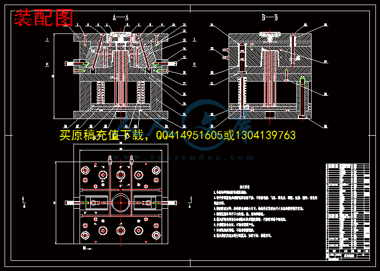
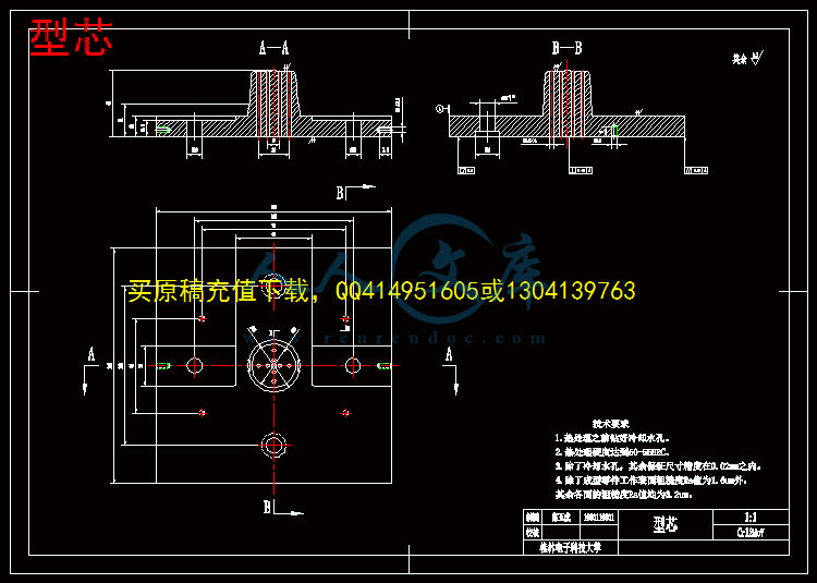
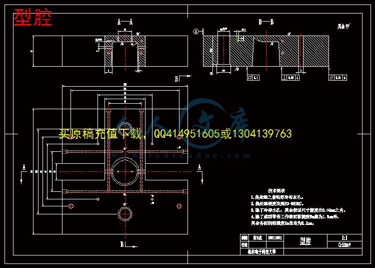
装配图.dwg
装配图.dwg

时尚艺术板凳注塑模具设计【17张CAD图纸+毕业答辩论文】【注塑模具】

收藏

资源目录
跳过导航链接。
压缩包内文档预览:
预览图
编号:444510    类型:共享资源    大小:3.58MB    格式:RAR    上传时间:2015-06-27 上传人:好资料QQ****51605 IP属地:江苏
45
积分
关 键 词:
时尚 艺术 板凳 注塑 模具设计 全套 cad 图纸 毕业 答辩 论文 模具
资源描述:

摘要


注塑成型工艺已经在我国的农业、工业、制造业、国防及日常生活等方面广泛的运用。为了探究注塑成型工艺的生产过程及其模具的设计制造过程,本次毕业设计参考相关书籍,结合生活实际,对整套注塑模具的生产设计过程进行详细探究。

本文将对塑料板凳的注塑模具设计,详细描述了整套模具的设计过程。主要内容包括塑件的基本介绍、塑件的结构及成型工艺分析、材料的选择及成型工艺、注射机的选择及校核、模具的工作及结构原理、浇注系统的设计、成型零件的设计、侧向分型抽芯机构的设计、合模导向机构的设计、温度调节系统的设计、排气系统的设计、推出机构的设计等。在正确的分析材料的特点和塑件的工艺特点后,运用三维软件对塑件和模具的设计,制造及质量进行分析;运用CAXA软件绘制完整的模具装配图和其主要零件图。此次设计综合运用多中专业基础知识、如模具设计与制造基本理论、机械设计、材料成型基础、塑性成型工艺、计算机基础技术、模具CAD/CAM等。

通过对整个模具设计的过程,进一步加深对注塑成型工艺的了解,同时也巩固了对成型工艺的类型、结构、工作原理等的理论知识,以及在实践中总结并掌握模具设计的关键要点及其设计方法。


关键词: 成型工艺;设计;制造;塑料


Abstract


Injection molding process has been widely used in China's agricultural、 industrial、 manufacturing、defense and other aspects of daily life. In order to explore the injection molding process and mold production process design and manufacturing process, this graduation design reference books, combined with real life, the production of injection molds for the entire design process detailed inquiry.

This article will bench plastic injection mold design, detailed description of the entire mold design process. The main contents include a basic introduction to plastic parts, design selection and verification, working principle and structure of the mold, pouring system structure and plastic parts molding process analysis, choice of materials and molding process, injection machine, forming part of the design, side parting pulling mechanism design, design-oriented organization designed to mold temperature control system, the design of the exhaust system, the introduction of design institutions. After the characteristics and process characteristics of plastic parts correct analysis of the material, the use of three-dimensional software for plastic parts and mold design, manufacturing and quality analysis; using CAXA software to draw a complete mold assembly drawing and its major parts diagram. The design of the integrated use of multi-professional knowledge, such as mold design and manufacture of basic theory, mechanical design, material forming the basis of the plastic molding process, basic computer technology, tooling CAD / CAM and so on.

Key points through the entire mold design process, and further deepen their understanding of the injection molding process, but also to consolidate the process of forming the type, structure and operating principles of the theory of knowledge, as well as summary and master mold design and in practice.


Keywords: Molding process; design; making; plastic.


目    录


引言1

1  塑件的基本介绍2

1.1 塑件3D建模2

1.2 塑件名称2

1.3 塑件材料2

1.4 塑件前景3

1.5 塑件总体要求3

2  塑件的结构及工艺性分析4

2.1 塑件结构分析4

2.2 塑件的工艺性分析4

2.3 开模方向4

2.4 脱模斜度5

2.5 收缩率5

2.6 表面粗糙度5

2.7 塑件壁厚6

2.8 圆角6

3  材料的选择与工艺参数7

3.1 材料的选择及其性能7

3.2 塑件的成型工艺8

4  注射机的选择及校核10

4.1 注射机的相关参数10

4.2 注射机的选择11

4.3 锁模力的校核11

4.4 开模行程的校核12

5  模具的工作及结构原理说明13

5.1 模具的工作原理13

5.2 模具的结构说明13

6  浇注系统的设计15

6.1 浇注系统的设计要求15

6.2 型腔的数目及分布15

6.3 双分型面的选择与设计16

6.4 主流道的设计17

6.5 分流道的设计18

6.6 冷料穴的设计19

6.7 浇口的设计19

7  成型零部件的设计21

7.1 凹模的设计21

7.2 凸模的结构设计22

7.3 成型零部件尺寸的设计22

8  侧向分型抽芯机构的设计25

8.1 斜导柱的倾角25

8.2 斜导柱直径设计25

8.3 斜导柱长度的设计26

8.4 滑块的设计26

8.5 导滑槽的设计27

8.6 楔紧块的设计27

8.7 滑块定位的设计27

9  合模导向机构的设计28

9.1 导柱、导套的设计28

10  温度调节系统的设计30

10.1 温度调节系统的设计要求30

10.2 冷却回路的设计30

11  排气系统的设计31

12  推出机构的设计32

12.1 顶出力的计算32

12.2 凝料推出机构的设计33

13  支撑零部件设计34

14  常见问题及其解决办法35

14.1 熔接痕产生的原因及解决办法35

14.2 充模不力产生的原因及解决办法35

14.3 弯曲变形产生的原因及解决办法35

结论37

谢辞38

参考文献39


引言

随着我国工业技术的飞跃性发展,模具在我国国民经济的各个领域中发挥越来越大的作用,享有着“工业之母”的美称。模具制造是指通过注塑、压铸和锻压等方式得到所需的各种产品或工件,一个设计合理的塑件往往能够代替几个传统金属构件。利用塑性材料独有的特性,一次注塑成型往往就可以得到非常复杂的形状,所带来的实际应用效果非传统工艺所能相比。模具的生产与制造融合了多项高精密技术为一体,既是高新技术产品,又是高新技术载体。采用模具成型工艺,运用高新技术控制对所需的塑件进行加工生产,不仅可以提高生产时效,保质保量。而且还能减少生产线对材料的过度依赖,压缩了生产成本,更好的获取经济效益。

注塑成型是塑性成各个领域型加工中最常见的加工方法,其中注塑模具已经被广泛的采用。它的成型效果、制造精度、生产周期以及生产效率的高低,直接影响到产品的质量、产量和成本。注塑成型现已被广泛的应用于机械、电子、航空、航天、军工、交通、汽车、建材、医疗器械、生物、能源和日用品等领域。在一些发达国家,模具的生产制造早已形成产业链,成为这些国家的基础经济工业之一。模具产业,在美国被成为“美国工业的基石”,在日本被称为“促进社会富裕的源泉、动力”。工业要发展,模具要先行。没有高水平的模具产业链就没有高水平的工业产品。现在,模具工业水平是衡量一个国家制造工业制造水平高低的重要标志。

综上所述,进行模具设计是一项综合性的研究,其目的和意义在于以下几点:

(1)查阅中内外文献检索和阅读的能力;

(2)运用专业理论,解决实际问题的能力;

(3)设计,绘图的能力,包含计算机的使用能力;

(4)对模具设计制造的初步了解及掌握;

(5)形象思维和逻辑思维相结合的表达能力;

(6)撰写毕业论文的能力;

(7)养成认真、严肃、严谨的作风。


内容简介:
编号: 毕业设计(论文)外文翻译(原文)学 院: 国防生学院 专 业: 机械设计制造及其自动化 学生姓名: 陈玉成 学 号: 1000110101 指导教师单位: 机电工程学院 姓 名: 曹泰山 职 称: 讲 师 2014年 3 月 9 日第 17 页 共 18 页桂林电子科技大学毕业设计(论文)说明书用纸A METHODOLOGY FOR THE DESIGN OF EFFECTIVE COOLING SYSTEM IN INJECTION MOULDINGInt J Mater Form (2010) Vol. 3 Suppl 1:13 16DOI10.1007/s12289-010-0695-2Springer-VerlagFrance2010ABSTRACTIn thermoplastic injection molding, part quality and cycle time depend strongly on the cooling stage. Numerous strategies have been investigated in order to determine the cooling conditions which minimize undesired defects such as war page and differential shrinkage. In this paper we propose a methodology for the optimal design of the cooling system. Based on geometrical analysis, the cooling line is defined by using conformal cooling concept. It defines the locations of the cooling channels. We only focus on the distribution and intensity of the fluid temperature along the cooling line which is here fixed. We formulate the determination of this temperature distribution, as the minimization of an objective function composed of two terms. It is shown how this two antagonist terms have to be weighted to make the best compromise. The expected result is an improvement of the part quality in terms of shrinkage and war page.KEYWORDS: Inverse problem;heat transfer;injection molding;Cooling design1. INTRODUCTIONIn the field of plastic industry, thermoplastic injection molding is widely used. The process is composed of four essential stages: mould cavity filling, melt packing, solidification of the part and ejection. Around seventy per cent of the total time of the process is dedicated to the cooling of the part. Moreover this phase impacts directly on the quality of the part 1 2. As a consequence, the part must be cooled as uniformly as possible so that undesired defects such as sink marks, warpage, shrinkage, thermal residual stresses are minimized. The most influent parameters to achieve these objectives are the cooling time, the number, the location and the size of the channels, the temperature of the coolant fluid and the heat transfer coefficient between the fluid and the inner surface of the channels. The cooling system design was primarily based on the experience of the designer but the development of new rapid prototyping process makes possible to manufacture very complex channel shapes what makes this empirical former method inadequate. So the design of the cooling system must be formulated as an optimization problem.1.1 HEAT TRANSFER ANALYSISThe study of heat transfer conduction in injection tools is a non linear problem due to the dependence of parameters to the temperature. However thermo physical parameters of the mould such as thermal conductivity and heat capacity remain constant in the considered temperature range. In addition the effect of polymer crystallization is often neglected and thermal contact resistance between the mould and the part is considered more often as constant. The evolution of the temperature field is obtained by solving the Fouriers equation with periodic boundary conditions. This evolution can be split in two parts: a cyclic part and an average transitory part. The cyclic part is often ignored because the depth of thermal penetration does not affect significantly the temperature field 3.Many authors used an average cyclic analysis which simplifies the calculus, but the fluctuations around the average can be comprised between 15% and 40% 3.The closer of the part the channels are, the higher the fluctuations around the average are. Hence in that configuration it becomes very important to model the transient heat transfer even in stationary periodic state. In this study, the periodic transient analysis of temperature will be preferred to the average cycle time analysis. It should be noticed that in practice the design of the cooling system is the last step for the tool design. Nevertheless cooling being of primary importance for the quality of the part, the thermal design should be one of the first stages of the design of the tools.1.2 OPTIMIZATION TECHNIQUES IN MOULDINGIn the literature, various optimization procedures have been used but all focused on the same objectives. Tang et al. 4 used an optimization process to obtain a uniform temperature distribution in the part which gives the smallest gradient and the minimal cooling time.Huang 5 tried to obtain uniform temperature distribution in the part and high production efficiency i.e. a minimal cooling time. Lin 6 summarized the objectives of the mould designer in 3 facts. Cool the part the most uniformly, achieve a desired mould temperature so that the next part can be injected and minimize the cycle time.The optimal cooling system configuration is a compromise between uniformity and cycle time. Indeed the longer the distance between the mould surface cavity and the cooling channels is, the higher the uniformity of the temperature distribution will be 6. Inversely, the shorter the distance is, the faster the heat is removed from the polymer. However non uniform temperatures at the mould surface can lead to defects in the part. The control parameters to get these objectives are then the location and the size of the channels, the coolant fluid flow rate and the fluid temperature. Two kinds of methodology are employed. The first one consists in finding the optimal location of the channels in order to minimize an objective function 4 7. The second approach is based on a conformal cooling line.Lin 6 defines a cooling line representing the envelop of the part where the cooling channels are located. Optimal conditions (location on the cooling and size of the channels) are searched on this cooling line. Xu et al. 8 go further and cut the part in cooling cells and perform the optimization on each cooling cell.1.3 COMPUTATIONAL ALGORITHMSTo compute the solution, numerical methods are needed. The heat transfer analysis is performed either by boundary elements 7 or finite elements method 4.The main advantage of the first one is that the number of unknowns to be computed is lower than with finite elements. Only the boundaries of the problem are meshed hence the time spent to compute the solution is shorter than with finite elements. However this method only provides results on the boundaries of the problem. In this study a finite element method is preferred because temperatures history inside the part is needed to formulate the optimal problem. To compute optimal parameters which minimize the objective function Tang et al. 4 use the Powells conjugate direction search method. Mathey et al. 7 use the Sequential Quadratic Programming which is a method based on gradients. It can be found not only deterministic methods but also evolutionary methods.Huang et al. 5 use a genetic algorithm to reach the solution. This last kind of algorithm is very time consuming because it tries a lot of range of solution. In practice time spent for mould design must be minimized hence a deterministic method (conjugate gradient) which reaches an acceptable local solution more rapidly is preferred.2 METHODOLOGY2.1 GOALSThe methodology described in this paper is applied to optimize the cooling system design of a T-shaped part (Figure 1). This shape is encountered in many papers so comparison can easily be done in particularly with Tang et al. 4.Based on a morphological analysis of the part, two surfaces 1 and 3 are introduced respectively as the erosion and the dilation (cooling line) of the part (Figure 1). The boundary condition of the heat conduction problem along the cooling line 3 is a third kind condition with infinite temperatures fixed as fluid temperatures. The optimization consists in finding these fluid temperatures. Using a cooling line prevents to choose the number and size of cooling channels before optimization is carried out. This represents an important advantage in case of complex parts where the location of channels is not intuitive. The location of the erosion line in the part corresponds to the minimum solidified thickness of polymer at the end of cooling stage so that ejectors can remove the part from the mould without damages.Figure 1 : Half T-shaped geometry2.2 OBJECTIVE FUNCTIONIn cooling system optimization, the part quality should be of primarily importance. Because the minimum cooling time of the process is imposed by the thickness and the material properties of the part, it is important to reach the optimal quality in the given time. The fluid temperature impacts directly the temperature of the mould and the part, and for turbulent fluid flow the only control parameter is the cooling fluid temperature. In the following, the parameter to be optimized is the fluid temperature and the determination of the optimal distribution around the part is formulated as the minimization of an objective function S composed of two terms computed at the end of the cooling period (Equation (1). The goal of the first term S1 is to reach a temperature level along the erosion of the part. 3 CONCLUSIONSIn this paper, an optimization method was developed to determine the temperature distribution on a cooling line to obtain a uniform temperature field in the part which leads to the smallest gradient and the minimal cooling time. The methodology was compared with those found in the literature and showed its efficiency and benefits. Notably it does not require specifying a priori the number of cooling channels. Further work will consist in deciding a posteriori the minimal number of channels needed to match the solution given by the optimal fluid temperature profile.An integrated framework for die and mold cost estimation using design features and tooling parametersReceived: 5 August 2003 / Accepted: 6 January 2004 / Published online: 2 February 2005 Springer-Vela London Limited 2005AbstractTooling is an essential element of near net shape manufacturing processes such as injection molding and die casting, where it may account for over 25% of the total product cost and development time, especially when order quantity is small. Development of rapid and low cost tooling, combined with a scientist approach to mold cost estimation and control, has therefore become essential. This paper presents an integrated methodology for die and mold cost estimation, based on the concept of cost drivers and cost moodier. Cost drivers include the geometric features of cavity and core, handled by analytical cost estimation approach to estimate the basic mold cost. Cost moodier include tooling parameters such as parting line, presence of side core(s), surface texture, ejector mechanism and die material, contributing to the total mold cost. The methodology has been implemented and tested using 13 industrial examples. The average deviation was 0.40%. The model is edible and can be easily implemented for estimating the cost of a variety of molds and dies by customizing the cost moodier using quality function deployment approach, which is also described in this paper.Keywords:Cost estimation; Die casting; Injection molding; Quality function deployment。1 IntroductionProduct life cycles today are typically less than half of those in the 1980s, owing to the frequent entry of new products with more features into the market. Manufacturing competitiveness is measured in terms of shorter lead-time to market, without scribing quality and cost. One way to reduce the lead-time is by employing near net shape (NNS) manufacturing processes, such as injection molding and die casting, which involve fewer steps to obtain the desired shape. However, the tooling (die or mold), which is an essential element of NNS manufacturing, consumes considerable resources in terms of cost, time and expertise.A typical die casting die or plastic injection mold is made in two halves: moving and axed which butt together during mold ling and move apart during part ejection. The construction of a typical cold chamber pressure die casting die is shown in Fig. 1.The main functional elements of the die and mold include the core and cavity, which impart the desired geometry to the incoming melt. These may be manufactured as single blocks or built-up with a number of inserts. The secondary elements include the feeding system, ejection system, side core actuators and fasteners. The feeding system comprising of spree bush, runner, gate and overawe enables the town of melt from machine nozzle to mold cavity. The ejector mechanism is used for ejecting the molded part from the core or cavity. All the above elements are housed in a mold base set, comprising of support blocks, guides and other elements. Part-specie elements, including core and cavity and feeding system are manufactured in a tool room. Other elements are available as standard accessories from vendors. Mold assembly and functional trials are conducted by experienced toolmakers in consultation with tool designers.Fig. 1. Construction of a typical pressure diecasting dieThe tooling industry is presently dominated by Japan, Germany, USA, Canada, Korea, Taiwan, China, Malaysia, Singapore and India. The major users of tooling include automobiles, electronics, consumer goods and electrical equipment sectors. Plastic molds account for the major share of tooling industry. About 60% of tool rooms belong to small and medium scale industries worldwide 1. The tooling requirement is over US$ 600 million per year in India alone, with an annual growth rate of over 10% during the last decade. In India, the share of different types of molds and dies is: plastic molds 33%, sheet metal punches and dies 31%, die casting dies 13%, jigs & stores 13%, and gauges 10% 2.The tooling industry is increasingly facing the pressure to reduce the time and cost of die and mold development, offer better accuracy and surface knish, provide edibility to accommodate future design changes and meet the requirements of shorter production runs. To meet these requirements, new technologies like high speed machining, hardened steel machining, process modeling, tooling design automation, concurrent engineering, rapid prototyping and rapid tooling have been applied. For successful operations and to maintain the competitive edge, it is necessary to establish quantitative methods for cost estimation.Our current research aims at developing a systematic and integrated framework for development of rapid hard tooling (dies and molds) for injection molding and pressure die-casting applications. The necessity of a systematic cost estimation model for comparative evaluation of different routes to tooling development motivated us to review the existing models, presented in the next section, followed by our proposed methodology.2 Previous worksThere is considerable similarity in cost estimation approaches used for product and tooling as reported in technical literature. These approaches can be classed into vet groups: intuitive, analogical, analytical, geometric feature based and parametric based methods, briery reviewed here.In the intuitive method, the accuracy of cost estimation depends on the cost appraisers experience and interpretations. The estimation is usually performed in consultation with the tool designer. The estimator acquires the wisdom and intuition concerning the costs through long association with dies and mold development. This method is still in practice in small workshops and tool rooms.In the analogical method, the cost of die and mold is estimated based on similarity coefficients of previous dies and molds manufactured by the rm. In this technique, dies are coded considering factors such as die size, die material, complexity, ejector and gating mechanism. The appraiser starts by comparing the new die design with the closest match among all previous designs. The basic hypotheses are: similar problems have similar solutions, and reuse is more practical than problem solving from scratch 3. However, this approach, also referred to as case based reasoning, requires a complete case base and an appropriate retrieval system, which has not been reported for die and mold cost estimation so far.In the analytical cost estimation, the entire manufacturing activity is decomposed into elementary tasks, and each task is associated with an empirical equation to calculate the Manufacturing cost. For example, a common equation for machining cost is:Machining cost = (cutting length / feed per minute) Machine operation cost.Wilson (quoted in 4, Chap. 6, p. 121) suggested a mathematical model for incorporating a geometric complexity factor in turning and milling operations, given by:di = i th dimension of featureti = corresponding dimensional toleranceN = total number of dimensions.This is explained with the help of an example later.Another method called activity based costing (ABC) involves applying the analytical method to all steps in manufacturing a given product, to estimate the resources (material, labor and energy) involved in each step. Such a detailed approach for various processes, including casting has been developed by Crease 5. In tool rooms, this approach is used in the case of dies with complex cavity geometry. The sources of mold cost can be divided into three categories: mold base cost, functional elements (core, cavity inserts) cost and secondary elements cost. In each category, the time needed to obtain the desired geometry by machining is considered as a reference for costing 4. As can be expected, establishing and validating the costing equation, as well as using it in practice, are cumbersome tasks.In the feature based method, mold geometric features (cylinder, slot, hole, rib, etc.) are used as the cost drivers. The die manufacturing cost is then estimated using either empirical equations or tools such as knowledge-based systems and arterial neural networks. Chen and Liu 6 used the feature recognition method to evaluate a new injection molded product design for its cost effectiveness. They assumed that a product is an aggregation of a set of features and feature relationships. These feature relationships were mapped to convert a part feature into mold related cost evaluations. Chin and Wong 7 used decision tables linked to a knowledge base to estimate injection mold cost.In the parametric cost estimation, technical, physical or functional parameters are used as basis for cost evaluation. This method allows one to proceed from technical values characterizing the product (available with design engineers) to economic data. Sandarac and Maslekar 8 used regression model approach in injection mold cost estimation. Lowe and Walshe 9 used labor involvement in injection mold making as a reference; mold cost was estimated using linear regression analysis.To summarize, cost similarity and cost functions (cost factors) are the two sets of methods for estimating the mold cost.In the rest set, similarity between a new mold and a previous mold developed in the tool rooms is used as a reference. Intuitive and analogical methods fall under this category. In the widely used intuitive method, the cost appraiser may not be in a position to identify all the risk factors and to quantify many of them. The analogical method can be successfully used for estimating the cost of die bases and other secondary elements where grouping is much easier. However, in the case of functional elements (core and cavity), grouping becomes a difficult task as their geometry, machining sequence and tolerance greatly vary with product design.In the second set of methods, the dependency between the mold cost and its drivers are expressed in mathematical functions. Analytical method, activity based costing, feature based method and parametric costing methods falls under this category. While analytical methods are well established for estimating the machining cost of simple parts, they are difficult to apply in die and mold manufacturing because of their geometric complexity. Similarly, feature based cost estimation is difficult to apply because the current feature recognition and classification algorithms cannot handle freeform surfaces present in most of the dies and molds, and other computational techniques like knowledge-based systems, fuzzy logic and arterial neural networks may be required to establish the cost relations. Further, these techniques may not be able to consider the impact of assembly restrictions, surface knish requirements, mold trials and other factors. The parametric costing method functions like a black box, by correlating the total cost of mold with a limited number of design parameters, and it is difficult to justify or explain the results.Menges and Mohren 10 developed an integrated approach for injection mold cost estimation, in which similar injection molds and structural components of the same kind are grouped together and a cost function for each group is determined. The cost components are grouped into cavity, mold base, basic functional elements and special functional elements. Machining cost for cavity and EDM electrodes is driven by machining time and hourly charges adjusted by factors like machining procedure, cavity surface, parting line, surface quality, axed cores, tolerances, degree of difficulty and number of cavities. The mold bases are assumed to be standard components. Cost of basic functional elements like sprue, runner systems, cooling systems and ejector systems are estimated on a case to case basis. The cost of special functional elements like side cores, three-plate mold, side cams and unscrewing devices is determined based on actual expenses. One of the limitations is that the machining time estimate based on mean cavity depth may not give accurate results in case of complex shaped molds that require different modes of machining like roughing, noshing and leftover material machining, due to cutting tool size and geometry constraints, orientations and settings. Secondly, the work does not appear to consider machining cost for secondary surfaces (particularly in case of built-in type cavities or cores), cost implications of mold material (which directly affects cutting tool selection and machining time), secondary operations on standard mold bases (to accommodate cavities, side cores and accessories, special ejector mechanisms and hot runners etc.), and some cushion in cost estimation to take care of additional work during nal machining of mating parts.This approach uses more than 1520 analytical models with average 58 variables, which need to be statistically established, and offers research opportunities.In general, all of above approaches give relatively accurate estimates only when tool rooms are involved in developing a single type of mold (such as injection molds or pressure die casting dies). Die and mold manufacturing is still regarded as skill and experience oriented manufacturing, and moreover it is not repetitive in nature. Thus there is a need to develop a generic die and mold cost estimation model that can be easily implemented for different types of molds and complexity, and is also edible to accommodate the decisions of the cost appraiser. We propose a cost model to meet the above requirements, based on the notion of cost drivers and cost modiers.Cost drivers depend on geometry and machining time. Cost moodier depend on complexity, and can be customized using a quality function deployment approach, which is also discussed in this paper.3 Framework for die and mold cost estimationThe cost components of a typical injection molded automotive part (assuming a die life of 250,000 parts) are given in Fig. 2 11. It shows that mold cost (41%) has a much larger share of total cost and therefore must be estimated accurately. Molds for other applications (pressure die casting, forging, sheet metal tools, etc.) also react a similar breakup. The mold cost comprises mold material, mold design and manufacturing. Among these mold-manufacturing costs represents the largest share and is the focus of our work. The structure of the proposed mold cost estimation model is shown in Fig. 3. In this approach, all geometric features are mapped to machining features, which are used as cost drivers and their cost is obtained by the analytical costing method. Other factors affecting the complexity of the die and mold are considered as cost moodier. Hereafter, the term mold will be used to represent both die and mold.3.1 Cost drivers: core and cavity featuresIn feature based design, a part is constructed, edited and manipulated in terms of geometric features (such as whole, slot, rib and boss) with certain spatial and functional relationships. The part features are used for generating mold cavity features; Table 1 shows the feature mapping between part and mold. The mold features are analyzed to identify the geometric dimensions, manufacturing processes and relative manufacturing cost. Essentially, the size and shape complexity of mold cavity features, which in turn nuance the selection of the manufacturing method, act as cost drivers. The manufacturing methods 1D,2D, etc., represent the simultaneous movement of tool or work piece with respect to axis X, Y , Z, a, b and c, to get the desired geometry. The relative cost for feature manufacturing (basic mold cost) is proposed based on our experience. This is useful when sufficient mold design and cost data are not available. More precise cost estimation can be assured by integrating analytical costing methods with machined features in later stages.The manufacturing cost of mold geometry can be calculated by Eq. 1 using predetermined machining parameters like feed per minute (S) and machine hour rate. The summation of machining cost of all features gives the basic mold cost:L f = Total cutting length of feature ( f = 1 to n)S = Corresponding feed (mm/min)M f = Corresponding machine minute rate (hour rate /60)I f = Machining complexity factor In = number of features .While calculating the machining complexity factor for cost estimation purposes, it is not necessary to consider all dimensions of a feature (the process engineer will select the manufacturing process and corresponding machine considering the geometry as well as tolerance of primary dimension). The machine hour rate already considers these effects. There are other factors like the number of settings, number of tooling and their sequence, which are again dependent on geometric complexity (number of surfaces and their orientation and special relationships). We therefore muddied Eq. 1 by introducing a machining process constant “K”. The value of K varies from 0.05 for plain turning to 0.5 for EDM and machine polishing processes.Thus machining complexity factor of a feature is given by:For example, consider a circular whole feature with diameter 20+0.018 mm and depth 160.010 mm. In this case, diameter 20 is a primary dimension and tolerance 18 m can be achieved by the reaming operation. Therefore, it becomes necessary to consider only the depth that is, 160.010. Reaming operation is normally performed in either CNC vertical machining center or a jig-boring machine. The number of settings is one, and the number of tooling is four (center drill, pilot drill, nal drill and machine reamer). Therefore, the machining process constant is considered as 0.2. Hence the machining complexity of the above feature is given by:3.2 Cost moodier: Die complexity factorsIn die and mold manufacturing, there are many die complexity factors that have a sign cant impact on the total cost and are considered as cost moodier. These include parting surface complexity, presence of side cores, surface nish and texture, ejector mechanism and die material. Their values, established from our experience, are given in Tables 24, as a percentage of the basic mold cost (derived from Eq. 3). These are explained in detail here.3.2.1 Parting surface complexitySelection of the most appropriate parting surface is an important activity in die and mold design. Many researchers have reported different algorithms to identify a parting surface considering the ejection of part from die cavity, ease of manufacturability and aesthetic issues. A complex parting signicantly increases the manufacturing cost due to increase in machining complexity (because of cutting tool geometry constraints) and die assembly time. A non-planar parting surface makes it difficult to match the two halves. Often it results in re-machining, which is not quant able by feature based approach. To consider these uncertainties, die parting surface complexity is divided into three levels: straight, stepped and freeform parting surfaces. Straight parting surface will not impose any additional cost; however the cost implications of steeped and freeform parting surface will 1020% and 2040%, respectively. This can also be customized as discussed in a later section.3.2.2 Presence of side coresThe product geometry may comprise a number of undercuts to the line of draw, hindering its removal from the die and mold. This is overcome by the use of side cores, which slide in such a way that they get disengaged from the molded part before its ejection. Side cores need secondary elements like guide ways, cams and hydraulic-pneumatic actuators, which impose an additional cost. If product geometry calls for a number of side cores that are actuated in different directions, then die size and cost will increase signicantly. Aggravated by additional die cooling arrangements, increased mold assembly time and nish machining during assembly, which may not be easily quant able. While the cost of side cores machining is already considered in cost drivers, their inuence on over all die complexity due to additional accessories, and secondary machining is considered here. The corresponding values for this cost moodier (c ) are given in Table 2 based on our experience.3.2.3 Surface nish and textureThe die surface is usually polished to obtain surface roughness Ra from 0.2 to 0.8 m. Some surface textures may be added to injection-molded parts to increase the aesthetic look or some functional requirement. This requires specialized processes like EDM texturing, photo etching and surface treatment, increasing the toolmakers job. Therefore, polishing and texturing impose additional cost, and the values for this cost moodier ( p ) are listed in Table 3 based on our experience.3.2.4 Ejection mechanismThe mechanism for ejecting a part from its mold or die may comprise a simple ejector pin or cam operated mechanism, or a complex hydraulic-pneumatic actuator. Construction of the ejector mechanism depends on the part geometry and the desired rate of production. In addition, ejector design may lead to a larger die size to accommodate the sliders, cams, actuators, etc. The ejector materials are usually of special grade, requiring hardening and nit riding treatments. Therefore, the ejector mechanism adds to the total cost depending on its type. The values for this cost moodier (e ) are given in Table 4.3.2.5 Die and mold materialThe die and mold material should have good mechanical properties like high hardness, low thermal distortion, high compressive strength and manufacturability. Commonly used tool steels for injection molds and pressure die casting dies include P20, P18, EN-24, A3, D1, D2, H11 and H13, which are more expensive than general steels. The die material cost is directly based on the Volume of die inserts (considered in the total cost model). The die material also affects the feature manufacturing cost, because of its impact on cutting tool life. A recent development is high speed machining of hardened die steel, which shows sign cant improvement in accuracy and surface nish. Based on an average of ten case studies carried out at our center, the die material factor (m ) can increase the basic mold cost by 210%, for die materials ranging from carbon steel to hot die steel.4 Establishing the cost moodierAs seen from Tables 24, the impact of various factors on the total cost of a die or mold cost is sign cant. While the values given in the above tables are based on our experience, they cannot be jostled in other tool rooms, unless they have a large case base to verify the same. The cost moodier must therefore be customized for an individual tool room.One way to customize the cost moodier is by using multiple regression analysis. This involves collecting historical data and establishing the regression coefficient or cost estimating relationships (CERs). However, the CERs established in commercial tool rooms may not simulate the real situation, since such tool rooms manufacture a large variety of dies and molds, and a huge amount of historical data would be required for computation.We propose another approach, based on quality function deployment (QFD) for establishing the cost moodier, to overcome the above limitation.This QFD-based cost model is project specie, and establishes the cost factors by considering the different tooling parameters. The user has to assess the impact of tooling parameters (parting surface complexity, surface nish, etc.) by considering basic mold cost as a reference. This improves the accuracy of total cost estimation. Table 5 explains the tooling parameters and theirAssociated cost factors considered in developing the QFD-based cost model. The steps involved in the methodology are as follows:1.Identify major tooling parameters other than basic die and mold feature manufacturing.2. Categorize the tooling parameters into different complexity levels (columns of QFD).3. Identify cost elements other than basic mold manufacturing cost (rows of QFD).4. Represent the importance of these cost elements in percent age of basic mold cost. For example, parting surface machining cost is about 10% of basic mold cost, and hence 0.1 is used as cost appraisers preference.5. Develop the relationship matrix considering the complexity, using 19 scale (1 = weak, 3 = medium, 9 = strong)6. Construct the correlation matrix using 0.11.0 scale (0.1 =weak, 0.3 = medium, 0.9 = strong)7. Normalize the relationship matrix using the Wasserman method. The coefficient of the normalized matrix is given by the following equation 12:8. Calculate the technical importance of each tooling parameter.9. The technical importance values can be used as respective cost moodier. The entire methodology for die and mold cost estimation is illustrated with an industrial example in Sect. 5.Fig. 4. Pressure die cast component and die inserts5 Industrial examplesFigure 4 shows an aluminum part used in ceiling fans, along with the corresponding die inserts. The fan component is produced using cold chamber pressure die casting process. The die design and development was relatively difficult as the part consists of a number of small geometric features and split parting surface. A combination of CNC and EDM processes are used to manufacture core and cavity die inserts in H13 material. Mold bases, ejectors and screws are purchased from standard vendors.5.1 Basic mold manufacturing costA CAD model of the casting was used as input to design the die. To estimate the basic mold cost, the mold machining features and the corresponding processes were rest indented. Then the feature machining cost was estimated using Eq. 3. The feature and its critical dimensions did (I the dimension of feature) and corresponding dimensional tolerance it (dimensional tolerance of i th dimension) were considered in calculating the complexity factor. The results are shown in Table 6. The following rates were used (in Indian Rupees; 1 INR US$ 0.02):5.2 Cost moodierThe main complexity characteristics of the die considered in this example are as follows:1.Straight parting surface (simple)2.Circular cavity split on both sides (chances of mismatching)3.12 ejector pins (diameter minimum 3 mm, maximum 8 mm)4.Die material H13 (needs hardening and tempering, hard to machine)5.Surface nish Ra 0.4 m (needs polishing)6.Number of side cores: Nil7.Number of core pins: 12 + 1 (alignment is critical).The QFD model was developed as discussed
温馨提示:
1: 本站所有资源如无特殊说明,都需要本地电脑安装OFFICE2007和PDF阅读器。图纸软件为CAD,CAXA,PROE,UG,SolidWorks等.压缩文件请下载最新的WinRAR软件解压。
2: 本站的文档不包含任何第三方提供的附件图纸等,如果需要附件,请联系上传者。文件的所有权益归上传用户所有。
3.本站RAR压缩包中若带图纸,网页内容里面会有图纸预览,若没有图纸预览就没有图纸。
4. 未经权益所有人同意不得将文件中的内容挪作商业或盈利用途。
5. 人人文库网仅提供信息存储空间,仅对用户上传内容的表现方式做保护处理,对用户上传分享的文档内容本身不做任何修改或编辑,并不能对任何下载内容负责。
6. 下载文件中如有侵权或不适当内容,请与我们联系,我们立即纠正。
7. 本站不保证下载资源的准确性、安全性和完整性, 同时也不承担用户因使用这些下载资源对自己和他人造成任何形式的伤害或损失。
提示  人人文库网所有资源均是用户自行上传分享,仅供网友学习交流,未经上传用户书面授权,请勿作他用。
关于本文
本文标题:时尚艺术板凳注塑模具设计【17张CAD图纸+毕业答辩论文】【注塑模具】
链接地址:https://www.renrendoc.com/p-444510.html

官方联系方式

2:不支持迅雷下载,请使用浏览器下载   
3:不支持QQ浏览器下载,请用其他浏览器   
4:下载后的文档和图纸-无水印   
5:文档经过压缩,下载后原文更清晰   
关于我们 - 网站声明 - 网站地图 - 资源地图 - 友情链接 - 网站客服 - 联系我们

网站客服QQ:2881952447     

copyright@ 2020-2025  renrendoc.com 人人文库版权所有   联系电话:400-852-1180

备案号:蜀ICP备2022000484号-2       经营许可证: 川B2-20220663       公网安备川公网安备: 51019002004831号

本站为文档C2C交易模式,即用户上传的文档直接被用户下载,本站只是中间服务平台,本站所有文档下载所得的收益归上传人(含作者)所有。人人文库网仅提供信息存储空间,仅对用户上传内容的表现方式做保护处理,对上载内容本身不做任何修改或编辑。若文档所含内容侵犯了您的版权或隐私,请立即通知人人文库网,我们立即给予删除!