音箱面壳模具设计说明书.doc

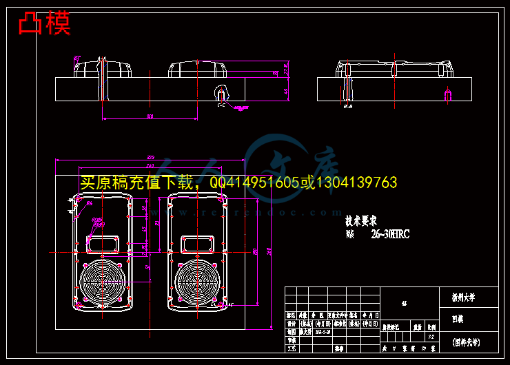
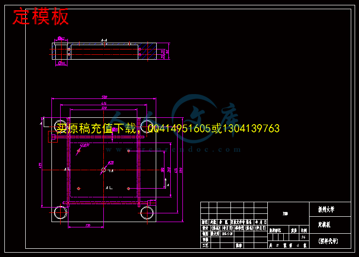
音箱面壳模具设计【三维PROE】【11张CAD图纸+毕业答辩论文】【注塑模具】

收藏

资源目录
跳过导航链接。
压缩包内文档预览:(预览前20页/共49页)
预览图 预览图 预览图 预览图 预览图 预览图 预览图 预览图 预览图 预览图 预览图 预览图 预览图 预览图 预览图 预览图 预览图 预览图 预览图 预览图
编号:444533    类型:共享资源    大小:13.48MB    格式:RAR    上传时间:2015-06-27 上传人:好资料QQ****51605 IP属地:江苏
50
积分
关 键 词:
音箱 模具设计 三维 proe 全套 cad 图纸 毕业 答辩 论文 注塑 模具
资源描述:

摘 要

近年来,我国的模具发展迅速,尤其是塑料模具提出了越来越高的要求,最近几年,塑料模具在整个模具行业所占的比例上升到30%左右,相信在未来的时间里,中国塑料模具工业还将保持年均增长速度达到10%以上较高速度的发展,国内塑料模具市场以注塑模具需求量最大。将来注射模具发展的方向向更精密、更高效、复合和多功能、更大型、更精密、更复杂、更绿色及更经济的方向发展,模具产品的技术含量将不断提高,模具制造周期将不断缩短。

注射成型是塑料成型的一种重要的方法,它主要适用于热塑料的成型,可以一次成型简单或复杂的精密塑件。本课题是将音箱作为设计模型,将注塑模具的相关知识作为依据,介绍塑件结构形状,塑件的材料选择,及塑件的结构工艺性,注射机成型的设备组成分类及型号规格。

本课题通过对音箱外壳成型工艺的分析,设计了一副一模两腔的塑料模具。设计成型零部件时,根据塑料的特性、塑件的结构和使用要求,确定型腔的总体布局,选择分型面,确定脱模方式,设计浇注系统、冷却系统。计算成型零部件的工作尺寸。运用Pro/E软件完成音箱外壳模具的整体设计;应用Pro/E中的塑料顾问模块(Plastic Advisor),对塑料制品进行注射仿真分析。最后对三维造型使用Pro/Engineer形同转出dwg文件进行出图。


关键词:注塑模具;注射机;Pro/Engineer;EMX(模架设计专家)


Abstract

. In recent years, China's rapid development of the mold, especially the plastic mold of the increasingly high demand, in recent years, the plastic mold in the mold industry the proportion of up to 30% jobs, I believe in the coming years, China plastic mold industry will maintain an average annual growth rate of more than 10% high speed development, the domestic market to plastic mold injection mold greatest demand. The future development direction of injection mold to more sophisticated, more efficient, complex and multi-purpose, larger, more sophisticated, more complex, more green and more economic development, mold the technical content of the product will continue to improve, the manufacturing cycle of the die will shorten ceaselessly.

Plastic molding injection molding is an important method, which is mainly applied to the thermal plastic molding, molding can be a simple or complex precision plastic parts. This topic is the speaker as a design model, the injection mold related knowledge as the basis, elaborates the structure process of plastic products, injection molding machine equipment composition classification and specifications.

Through proper analysis of the speaker molding process, I designed a double-cavity plastic mould.While designing molding components, based on the characteristics of plastic, plastic parts of the structure and use requirements, the overall layout of the cavity, the joint face, the stripping methods, design of gating system, exhaust system should be determined. the working size of the molded parts is calculated. Then use Pro / E software to complete the overall design hair dryer shell mold; and finally  the plastic module consultant (Plastic Advisor) in Pro / E is applied for plastic injection simulation analysis. finally the3D modeling using Pro / Engineer DWG file is transferred out of a map.


Key words: Injection molding; injection machine; Pro/Engineer; EMX (formwork design expert)


目    录

摘要

Abstract

第一章 绪论1

1.1模具及模具工业的发展与现状1

1.2塑料成型模具的及其分类1

1.3注射模具的发展趋势1

第二章  塑料成型工艺2

2.1 塑件材料的选择2

2.2确定成型方法2

2.3注塑成型工艺过程3

2.3.1 成型前的准备3

2.3.2 注塑成型过程3

2.3.3、塑件的后处理4

2.4塑件的结构工艺性4

2.5 塑件成型工艺参数5

2.5.1 温度5

2.5.2 压力6

2.5.3 成型周期7

第三章 音箱面壳模具设计9

3.1注塑成型设备9

3.1.1注塑机结构组成9

3.1.2 注塑机的分类9

3.1.3 注塑机的型号规格10

3.2注射模具分类及典型结构10

3.2.1注射模分类10

3.2.2注射模典型结构10

3.3音箱模具的结构设计12

3.3.1分型面的设计12

3.3.2型腔数目的确定13

3.3.3 浇注系统的设计14

3.3.4 成型零件设计16

3.3.5 合模导向机构的设计19

3.3.6 推出机构设计20

3.3.7 模具温度调节系统设计22

3.3.8 标准模架的选用24

3.4 注射模具与注射机的关系25

3.4.1 选择注塑机25

3.4.2最大注射量的校核26

3.4.3 注射压力的校核26

3.4.4 锁模力的校核27

3.4.5 安装部分尺寸校核27

3.4.6 开模行程的校核27

3.4.7 推出装置的校核27

3.4.8 喷嘴的校核28

第四章 音箱面壳模具三维设计29

4.1音箱面壳三维造型及模具设计29

4.2 模架设计30

4.2.1 定义模具模架30

4.2.2 添加设备31

4.2.3 设计顶出机构33

4.2.4 设计冷却系统33

4.2.5 动画模拟开模35

第五章 音箱面壳模具注射仿真分析36

5.1 Pro/e塑料顾问的简介36

5.1.1注射仿真分析的优点36

5.1.2注射仿真分析的缺点36

5.2塑料顾问模块的进入36

5.3分析功能应用37

5.4分析结果38

5.4.1注射压力38

5.4.2注射温度38

5.4.3塑料熔体温度39

5.4.4熔接痕39

5.4.5气泡40

第六章 小结与展望41

6.1小结41

6.2展望41

致 谢42

参考文献43

附  录44


第一章 绪论

1.1模具及模具工业的发展与现状

在模具工业的总产值中,冲压模具约占50%,塑料模具约占33%,压铸模具约占6%,其他各类模具约占11%。在模具生产方面,国内已经能够生产精度达21µ m的精密多T位级进模、新轿车的部分覆盖件模具、48in(约122cm)大屏幕彩电塑壳注射模具、6.5kg大容量洗衣机全套塑料模具以及汽车保险杠和整体仪表板等塑料模具,还有照相机塑料件模具、多型腔小模数齿轮模等精密塑料模具。


内容简介:
扬州大学广陵学院毕业设计(论文)前期工作材料学生姓名: 徐文秀 学号: 100007135 系 部: 机电系 专 业: 机械设计制造及其自动化 设计(论文)题目: 音箱面壳模具设计 指导老师: 高 征 兵 材 料 目 录序号名 称数量备注1毕业设计(论文)选题、审题表12毕业设计(论文)任务书13毕业设计(论文)实习调研报告14毕业设计(论文)开题报告(含文献综述)15毕业设计(论文)外文资料翻译(含原文)16毕业设计(论文)中期检查表1 2014年 2 月 17 日注:毕业设计(论文)中期检查工作结束后,请将该封面与目录中各材料合订成册,并统一存放在“毕业设计(论文)资料袋中(打印件一律用A4纸型)。扬州大学广陵学院毕业设计选题、审题表学 院广陵学院选 题教 师姓名高征兵专 业机械设计制造及其自动化专业技术职务讲师申报课题名称 课题性质课题来源ABCD课题简介了解注塑模具,对模具的结构认识,使用现代CAD、CAM技术设计 模具。设计(论文)要 求(包括应具备的条件)1、实习报告2、毕业设计(论文)开题报告3、外文翻译4、设计塑料模具三维造型、模具型腔、模架 5、毕业设计(论文)说明书课题预计工作量大小大适中小课题预计难易程度难一般易所在专业审定意见:负责人(签名):年 月 日院主管领导意见: 签名: 年 月 日说明:1、该表作为本科学生毕业设计(论文)课题申报时专用,由选题教师填写,经所在专业有关人员讨论,负责人签名后生效;2、有关内容的填写见背面的填表说明,并在表中相应栏打“”课题一旦被学生选定,此表须放在“毕业设计(论文)资料袋”中存档。扬州大学广陵学院毕业设计(论文)任务书系 部: 机电系 专 业: 机械设计制造及其自动化 学生姓名: 徐文秀 学号: 100007135 毕业(论文)题目: 音箱面壳模具设计 起 迄 日 期: 2014-02-17 2014-06-01 设计(论文)地点: 指 导 老 师: 高 征 兵 专 业 负 责 人: 发任务书日期: 2014 年 2 月17 日任务书填写要求1、毕业设计(论文)任务书由指导老师根据各课题的具体情况填写,经学生所在专业的负责人审查、学院分管领导签字后生效。此任务书应在毕业设计(论文)开始前一周内填好并发给学生;2、任务书内容必须用黑墨水笔工整书写或按统一设计的电子文档标准格式(可在本学院网页上下载)打印,不得随便涂改或潦草书写,禁止打印在其它纸上后剪贴;3、任务书内填写的内容,必须和学生毕业设计(论文)完成的情况相一致,若有变更,应当经过所在专业的教科部及学院主管领导审批后方可重新填写;4、任务书内有关“教科部”、“专业”等名称的填写,应写中文全称,不能写数字代码。学生的“学号”要写全号,不能只写最后2位或1位数字;5、任务书内“主要参考文献”的填写,应按照国标GB 7714-87文后参考文献著录规则的要求书写,不能有随意性;6、有关年月日等日期的填写,应当按照国标GB/T 7408-94数据元和交换格式、信息交换、日期和时间表示法规定的要求,一律用阿拉伯数字书写。如“2005年3月21日”或“2005-03-21”。毕业设计(论文)任务书1、本毕业设计(论文)课题应达到的目的:(1)能够迅速检索和分析设计相关的文献资料; (2)能够翻译专业相关的外文文献,从中获取对设计有帮助的知识; (3)将大学四年课本所学知识与实践操作相结合并融会贯通; (4)理解塑料模具设计的全过程,熟悉塑料模具中上、下模的设计、模架的选用、模架的设计等学习模具设计的工艺流程,学会使用恰当的方法去设计模具;(5)熟悉Pro/e软件中的基本命令、软件的模具设计、工程图的应用等2、本毕业设计(论文)课题任务的内容和要求(包括原始数据、技术要求、工作要求等):内容:(1)完成资料采集分析以及文献翻译和文献综述(2)利用Pro/e进行音箱面壳的实体造型(3)利用Pro/e设计模具上下模(4)上下模尺寸计算和标准件的选择(5)模具浇注系统和冷却系统的设计(6)模架的设计计算和选择(7)注塑机的参数的计算和选用(8)模具上下模运动仿真(9)毕业设计说明书的编写要求:(1)原始数据方面:对于论文中引用的原始数据必须真实,可靠,完整,并具有一定的权威性。(2)技术要求方面:模具设计的尺寸精度,制造精度,公差等级,工件性能,设计要求等必须满足设定标准。(3)工作要求方面:必须在导师的指导下认真完成额定任务,及时向导师汇报工作,积极主动交流,询问不懂的问题并解决。毕业设计(论文)任务书3、对本毕业设计(论文)课题成果的要求(包括毕业设计论文、图表、实物样品等):(1) 毕业设计说明书一份 (2) 音箱面壳三维造型和二维工程图各一份 (3) 模具上下模三维实体造型和二维工程图各一份 (4) 模具与模架、注塑机三维装配图和二维工程图各一份 (5) 各零部件图若干4、主要参考文献: (1)何满才 Pro/ENGINEER模具设计与Mastercam数控加工 人民邮电出版社 (2)单泉 Pro/ENGINEER Wildfire中文版模具设计专家指导教程 机械工业出版社(3)凯德. 精通Pro/Engineer中文野火版模具设计 中国青年出版社(4)张磊 Pro/ENGINEER Wildfire4.0 模具设计视频精讲 人民邮电出版社(5)胡仁喜 Pro/Engineer Wildfire中文版模具设计从入门到精通 机械工业出版社(6)李翔鹏 Pro/ENGINEER Wildfire 3.0 模具设计 中国铁道出版社(7)曹岩 Mastercam X6 数控加工从入门到精通 化学工业出版社(8)阮锋 模具设计与制造实用教程 机械工业出版社(9)杨宁宁 Pro/ENGINEER Wildfire 4.0 模具设计技术与实践清华大学出版社(10)野火科技 Pro/ENGINEER Wildfire 4.0 产品模具设计 清华大学出版社(11)王国中 注塑模具CAD/CAE/CAM技术 北京理工大学出版社(12)周永泰 我国塑料模具现状与发展趋势 北京市塑料研究所出版社(13)王立华 模具制作实训 清华大学出版社(14)邓明 现代模具制造技术 化学工业出版社(15)林慧国 模具材料应用手册 机械工业出版社(16)王孝培. 塑料成型工艺及模具简明手册. 机械工业出版社(17)邹继强. 塑料模具设计参考资料汇编 . 清华大学出版社16 杨占尧 自柳主编塑料模具典型结构设计实例化工公业出版社,200817 申开智主编.塑料成型模具(第二版) 中国轻工业出版社 200918 丁 浩主编. 塑料加工基础 上海科技出版社 199819 李秦蕊主编.塑料模具设计 西安工业大学出版社 1997 20 黄毅弘主编.模具制造工艺 机械工业出版社 1996毕业设计(论文)任务书5、本毕业设计(论文)课题工作进度计划起止日期工 作 内 容第13周了解相关知识、完成实习调研,作开题报告第4、5周完成模具结构设计,包括凸凹模具、模架的三维造型第6、7周完成相关的零件图、装配图。中期检查第810周撰写毕业设计说明书第11、12周完善相关资料、答辩所在专业审核意见:负责人: 年 月 日学院意见:院长:年 月 日实习报告实习单位:连云港康乐药业有限公司实习地点:赣榆华南路2号实习单位简介:连云港康乐药业有限公司是一家新建成投产的原料药生产企业,公司坐落于连云港市赣榆经济开发区,占地面积8万多平方米,建筑面积近2万平方米,总投资8000万元,所选的生产设备均达到国际、国内先进水平、拥有一流的化验仪器及检测设备和一支高学历、高素质的管理团队及员工队伍,于2004年11月正式投入生产。公司的主要产品是原料药对乙酰氨基酚(扑热息痛),产品主要出口尼日利亚、印度尼西亚、韩国、台湾、新加坡、香港等许多国家和地区作为一家新建的药品生产企业,拥有完全按照GMP标准建立的生产线,先进的检测设备,年生产对乙酰氨基酚(扑热息痛)6000吨,产品质量上乘,并且可以满足客户的各种要求及特殊加工,我公司以良好的售后服务来赢得广大客户的支持。本单位有8个部门,各司其职,保证企业的正常运转,工程部负责企业的各种设备的维护保养,负责企业的整体运转,和企业设备的改造,生产办负责管理车间,负责车间的生产和产量的多少。实验室负责检测产品是否合格,物流部门负责货物的接收和发放,污水负责处理生产产生的污水,QA负责检查各个部门的操作是否规范,车间是否整洁,个人SOP的考核是否达标,财务部负责员工工资的发放,和各个设备的购买批准,综合办负责人事的流动,这8个部门使得企业的运转井井有条。实习内容:我在2014年1月10号应聘到该企业实习,做为一名工程设备管理人员,主要了解各种化工产品如各类水泵,三足式离心机,吊臂式离心机,纯化水,动力车间,贮水罐等一系列设备的IQ,OQ,PQ以及它们的设备维修过程和注意事项,保证纯化水的供应,做好纯化水车间的各种记录,了解纯化水车间的运转流程,并知道纯化水车间的常见问题应该如何进行解决处理实习心得通过在康乐药业的实习,我了解到在学校学不到的知识,用了再学校用不到的知识,更加深刻的体验到将知识应用到实际中这句话的重要性,也体验到知识衔接的不容易,我们公司是制作对乙酰氨基酚。我的实习内容是保证制作流程的纯化水的供应。公司的制作流程是原料通过投料系统传送到酰化车间三楼的反应罐中进行反应,酰化三层主要包括酰化反应罐,终点酸计量罐,淡酸计量罐,冰醋酸计量罐,中酸计量罐,酰化母液回收罐,以及冷却塔,原料经过在反应罐和各种酸加入纯化水进行反应后进入到酰化二层的结晶罐中进行结晶。酰化二层不但有酰化结晶罐,还有圆孔石墨冷凝器,以及酰化母液回收罐。接下来进入到酰化一层进行离心,得到粗成品后进入到精烘包车间进行精制加工,最后得到成品,一部分送往温州的总公司,一部分卖往国内外,在实习期间,我充分了解了纯化水的制作过程,首先是原水箱,也就是饮用水,经过预处理,预处理包括石英砂过滤器,活性炭过滤器,树脂软化器(A/B),生成软化水以后,经过一级RO系统,变为一级纯化水,在经过中间水箱、二级RO系统,生成二级纯水,最后进入纯水箱首先是石英砂过滤器(去除杂质、悬移物),过滤介质为不同直径的石英砂分层填装,较大直接的介质通常位于过滤器顶端,水流自上而下通过逐渐精细的介质层,通常情况下介质床的孔隙率应允许去除微粒的尺寸最小为1040m,介质床主要用于过滤除去原水中的大颗粒,悬浮物,胶体及泥沙等以降低原水浊度对膜系统的影响,同时降低污染指数值,出水度要求小于1,污染指数(SDI)小于5,达到反渗透系统进水要求.其次是活性炭过滤器(小分子有机物、游离氯),主要用于去除水中的游离氯,色度、微生物,有机物以及部分重金属等有害物质,以防止它们对反渗透膜系统造成的影响。过滤介质通常由颗粒活性炭构成的固定层。经过处理后的小、出水余氯应小于0.1还有树脂软化器,软化器通常由装树脂的容器、树脂、阀或调节器以及控制系统组成。介质为树脂。目前主要是用钠型阳离子树脂中有可交换的正极阳离子交换出原水中的钙、镁离子从而降低水的硬度,一防止钙镁等离子在RO膜表面结垢,使原水变成软化水后出水硬度能达到很低软化器配备两个,当一个进行再生时,另外一个可以继续运行,确保生产的连续性。最后是反渗透系统,反渗透的原理是当在膜的盐水侧施加一个压力时,水的流向就会逆转,此时盐水中的水就会流入纯水侧,这种现象叫反渗透,纯水侧的水流入盐水侧,浓水侧的液位上升,当上升到一定的高度后,水通过膜的净流量等于零,此时该过程达到平衡,与该液位对应的压力成为渗透压这个工作,需要不时巡查各个设备的参数是否正常每小时需要记录原水箱和中间水箱的检验数值,每个月清洁一次原水箱和中间水箱,过滤器滤芯的清洗、消毒也是每个月一次而更换是三个月一次,纯化水车间的管道和储罐清洗消毒也是每个月一次,顶端过滤器滤芯的蒸汽消毒是每个月一次,而车间的清洁是每天都需要的,所有的清洁消毒都需要认真记录,参数是每小时记录一次,记录的数据必须及时、真实。这样可以在事故出现时找到原因。经过培训,我已经可以熟练掌握各种仪表仪器的应用,熟悉车间的运转流程,了解了基本问题的解决办法,虽然有时候会很辛苦,但是我觉得工作是一件令人骄傲的事情,我希望我可以把自己的工作做好扬州大学广陵学院毕业设计(论文)开题报告 学 生 姓 名: 徐文秀 学号:100007135 专 业: 机械设计制造及其自动化 设计(论文)题目: 音箱面壳模具设计 指 导 老 师: 高 征 兵 2014年 4 月 06 日开题报告填写要求1、开题报告(含“文献综述”)作为毕业设计(论文)答辩委员会对学生答辩资格审核的依据材料之一。此报告应在指导老师的指导下,由学生在毕业设计(论文)工作前期内完成,经指导教师签署意见及所在专业的教科部审核后生效;2、开题报告内容必须用黑墨水笔工整书写或按统一设计的电子文档标准格式(可从本学院网页上下载)打印,禁止打印在其它纸上后剪贴,完成后应及时交给指导教师签署意见;3、“文献综述”应按论文的格式成文,并直接书写(或打印)在本开题报告第一栏目内,学生写文献综述的参考文献应不少于15篇(不包括辞典、手册);4、有关年月日等日期的填写,应当按照国标GB/T 7408-94数据元和交换格式、信息交换、日期和时间表示法规定的要求,一律用阿拉伯数字书写。如“2005年3月21日”或“2005-03-21”。毕业设计(论文)开题报告1、结合毕业设计(论文)课题情况,根据所查阅的文献资料,每人撰写2000字左右的文献综述: 文 献 综 述我国注塑模具现状及发展方向,国外模具发展概况目前,我国模具生产厂点约有3万多家,从业人数80多万人塑料模具发展迅速,注塑模具比例进一步上升,注塑模具在质和量方面都有较快的发展,我国最大的注塑模具单套重量已经超过50吨,最精密的注塑模具精度已经达到2微米模具新结构、新品种、新工艺、新材料的创新成果不断涌现,特别是汽车、家电等工业快速发展,使得注塑模的发展迅猛。虽然整体来看我国塑料模具无论是在数量上,还是在质量、技术和能力等方面都有了很大进步,但与国民经济发展的需求、世界先进水平相比,差距仍很大,一些大型、精密、复杂、长寿命的中高档塑料模具每年仍需大量进口。在总量供不应求的同时,一些低档塑料模具却供过于求,市场竞争激烈,还有一些技术含量不太高的中档塑料模具也有供过于求的趋势。国内外注塑模部分性能指标对比如表1。表1注射速度国内:通常80mm/sec,大型机在65一700mm/sec国外:普遍大于100 mm/sec最高可达450 mm/sec塑化能力国内:通常不超过16g/sec;国外:通常在28g/sec以上,且随预塑马达转速提升和螺杆长径比和螺槽深度的改变,其塑化能力还在不断提升启闭模速度国内:普遍在24m/min国外:普遍已达到50m/min最高可达100m/min螺杆转速国外注塑机的螺杆转速高,比国内机普遍高25%。开模行程、拉杆间距距开模行程大、拉杆间距长、比国内机高15%左右.模板移动速度国内:20一30m/min国外:20一30 m/min所以,我国必须高度重视起塑料模具,尤其是注塑模具的发展 我国注塑模的设计制造水平比德、美、日、法等工业发达国家落后,主要是因为1供给不均匀。国内的自配率不均匀,低档的模具供过于求,中高档的模具的自配率不到60%。由于在模具精度、寿命、制造周期及生产能力等方面,我国与国际平均水平和发达国家仍有较大差距,因此,每年我国仍然需要大量进口模具。2人才不足,科技及技术投入不够。模具行业是技术密集、资金密集的产业。能掌握和运用新型技术的人才非常少,高级模具钳工及企业管理人才也供不应求。 3工艺装配水平低,虽然国内许多企业从国外购买了先进的加工设备,但总的看来装备水平仍落后许多,特别是设备数控化和CAD/CAM应用范围要比国外企业低得多。4标准化和商品化程度低。许多模具企业观念落后,模具企业专业化生产水平低,专业化分工不细,商品化程度也低目前国内每年生产的模具,大多为自产自用模具企业之间协作不好,难以完成较大规模的模具成套任务,与国际水平相比要落后许多。 5材料及相关技术落后,产业能源消耗大、产出率低导致环境污染严重和对自然资源破坏力大。另外,产业能耗大,产出率低、环境污染严重更是我国急需解决的问题。我国的模具产品应该1向大型,微型,精密化方向发展。2热流道、气辅模具及适应高压注塑成型工艺将得到进一步发展。3节能化和环保化以适应全球发展要求4快速经济模具的前景十分广阔5优质模具材料及先进表面处理技术将进一步受到重视。国外模具设计思想十分明确,模具尽可能以低造价、短周期、高质量去适应自动化生产并符合生产批量的各项要求,从而降低产品成本和价格,以获得最大的利润。国外多工位级进模大多采用镶拼结构,凸模用标准型式进行镶嵌,凹模拼块用环氧树脂结固定,普遍使用气动送料器,通过锁紧进给机构,利用压缩空气推动活塞往复进行送料。国外塑料模向一模多腔方向发展,型腔数量可多达1000个,尺寸精度5微米,并普遍采用热流道塑料模,这种模具的成本虽然比冷流道模具高20、30%,但工件成本却降低3050%在设备上面国外多采用数控(NC)和计算机控制(CNC)等高效自动化设备并且发展电加工技术、采用先进的检侧装置并运用了计算机集成制造及管理系统(CIMS) 再制造方面采用模具专业化和标准化,在材料上多应用新型材料如:粉末高速钢、高速钢基体钢、火焰淬火钢、高热强性耐磨钢、塑料模具钢、超塑性金属模具等新材料本次的设计任务是研究音箱面壳模具设计,做出一副完整的音箱面壳的注塑模具,通过设计能够熟悉和掌握冲压零件盒冲压模具的全过程,掌握模具主要零件的强度计算和每一个零件尺寸的确定,掌握制造工艺知识,通过该设计,能够熟练的运用计算机进行设计和绘图。本课题研究的主要内容和准备采用的研究方案1、 本课题需要研究或解决的问题: 此次设计的零件体积比较小,设计并不复杂,对模具制造设计的要求较高,对该零件的成型工艺的详细分析,根据它的特点,在模具设计中如何选择最快速的设计方法,最低的设计成本,首先应该选择CAD/CAM,但是要在设计中发挥它的主要优势,则应该选择Pro/Engineer,零件的设计可以运用Pro/E拉伸、拔模、倒圆角、抽壳边界混合等相关命令,因此,这次毕业设计的关键就是Pro/E设计软件在模具设计中的运用,凸凹模的设计是最为关键的部分,为了圆满的完成毕业设计,我对Pro/E的几个模块特别是零件、曲面、工程图和模具模块进行了深入的学习,希望可以圆满完成我的模具设计任务二、研究手段(途径)(一)、音箱面壳三维造型应用Pro/E中拉伸、拔模、倒圆角、抽壳、边界混合等相关命令生成的相机面壳,如下图所示。(二)、模具设计1、上、下模的设计 (1)根据音箱面壳工程图利用Pro/e进行其三维造型并生成零件图。 (2)模具型腔的布局; (3)拔模检测 (4)按比例收缩; (5)手动工件; (6)复制法生成分型面; (7)分模产生上下两个体积块 (8)创建镶件体积块; (9)抽取实体: (10)铸模2、模架的选用 (3) 、模架的设计(1)新建模架并装配模具 (2)型腔布局; (3)设计浇注系统 (4)创建顶杆基准点; (5)准备原件; (6)加载标准模架; (7)载入标准件; (8)固定型腔组件; (9)设计推出机构: (10)创建冷却水道(四)注射机选用后基本参数的校核毕业设计(论文)开题报告指导教师意见:1、对“文献综述”的评语:2、对本课题的深度、广度及工作量的意见和对设计(论文)结果的预测:指导老师: 年 月 日所在专业审查意见:负责人: 年 月 日扬州大学广陵学院毕业设计(论文)外文资料翻译系 部: 机电 专 业: 机械设计制造及其自动化 姓 名: 徐文秀 学 号: 100007135 外文出处Mold design and manufacturing professional (用外文写) English 附 件: 2.3注塑模具2.3.1 注塑成型注塑成型主要应用于生产热塑性塑料零件,而且它也是其中最古老的一种。目前注塑成型占所有塑料树脂消耗的30%。典型的注射成型产品的杯子,容器,壳体,工具手柄,旋钮,电线和通讯组件(如电话接收器),玩具,水暖配件。聚合物熔体由于其大的分子量而有着高的粘性,它们不能在重力下作用下直接注入像金属罐一样的模具中,但必须在高压下注入模具之中。因此,一个金属铸件的机械性能主要由热量从模具的外壁传递的速率来决定,并且这同时决定了最终铸件中的晶粒尺寸和晶粒方向。在注塑成型的过程中,注射熔体中的高压产生的剪切力是最终材料中分子取向的主要原因。因此,成品的机械性能是由注入条件和模具中的冷却条件共同决定的。注塑成型已经应用于热塑性材料和热固性材料,发泡部件,并具有被修饰以产生反应注射成型(RM)工艺,其中两个热固性树脂体系的组分同时注入模具中并在其中迅速的聚合,然而,大多数注塑成型过程在热塑性材料上执行,我们接下来的讨论内容将集中在这些成型上面。一个典型的注塑成型周期或顺序由五个阶段组成(见图2-1)(1) 注射或充模(2) 包装或压缩(3) 保持(4) 冷却(5) 部分弹出塑料颗粒(或粉末)被装进漏斗内,通过压射缸的开口并在那里被旋转的螺杆结转,螺杆的旋转迫使颗粒在高压下撞击热壁使它们融化。加热温度从265度到500度。随着压力的增大,旋转螺杆被迫向后挤压,直到足够的塑料被积累到能够使之发射。注射活塞(或螺钉)迫使熔融塑料从料筒,通过喷嘴,浇口和流道系统,最后进入模腔。在注入期间,模腔的容积被填充。当塑料接触冷作模具表面,它迅速凝固(冻结)产生表层。由于其核心保持在熔融状态下,塑料流过核心来完成模具填充,典型的,在注射过程中空腔被填充到95%98%。然后模塑过程转换到保压阶段。即使当空腔正在被填充,熔融的塑料就开始了冷却。因为冷却塑料的缩小和收缩,就会引发缺陷,例如凹痕,空隙和空间的不稳定。为了补偿收缩,剩余的塑料被挤压入模腔。一旦模腔被充满,压力施加到熔体上,防止腔体内的熔融塑料通过浇口从背后流出。压力必须持续施加知道大门处凝固。该过程可以分为两个步骤(填料和保持)或者在一个步骤中(保持或第二级)所包含。在填充过程中,熔体在填充压力作用下被压入空腔以用来补偿收缩。保持压力仅仅是为了防止聚合物熔体的倒流。在保持阶段之后,冷却阶段开始。在冷却过程中,部分是在模具中规定时间内完成。冷却阶段的持续时间主要取决于材料性能和零件厚度。通常,该部分的温度必须冷却到低于该材料的脱模温度。当冷却零件时,机器为下一个周期塑炼熔体。该聚合物是经受剪切力作用和加热器能量状态。一旦发射完成,塑化停止。这应该在冷却阶段截止之前的时候立刻发生,然后打开模具,零件排出。2.3.1 注塑模具模具的注射成型在设计中是多样化的,复杂度和大小都是不同的因为零件时从它们之中生产而来的。用于热塑性塑料模具的功能基本上给予了所希望的形状用来增塑聚合物然后进行冷却模塑的零件。一个模具有两个部分组成:(1)型腔和型芯和(2)支持型腔和型芯安装的基座。模具中的模塑部分的大小和重量限制了型腔的数量并确定了所需设备的能力。基于模制过程的考虑,模具已经被设计成能够安全吸收锁模,注射和喷射时的力量。除此之外,浇口和滑行装置设计必须允许高效流动和模腔的均匀填充。图2-2显示了一个典型的注射模的部分。模具基本上由两部分组成,一个固定的一半(模腔板),熔融的聚合物在这一侧注入,还有一个移动的另一半(核心板),在注塑设备关闭或者喷射器的一面。分离两个半模之间的线称为分割线。注入的材料经过中心进料通道转移,称作浇道。浇道位于浇道衬套内并逐渐变细,以便模具打开过程中从模具中释放浇道材料。在多型腔模具中,浇口流动的聚合物熔体构成流道系统,用来通过浇口进入每一个型腔。核心板块装置着主要核心部分。主要核心的目的是为了建立该部分内部结构。核心部分具有支持或支撑板。反过来支持模块通过支柱固定在称作U型结构的喷射器壳体上,这个壳体由后部夹板和隔板组成。这个用螺栓固定在核心板上的U型结构为输油行程也叫做冲孔行程提供空间。在凝固过程中围绕着主要核心部分收缩以至于当模具打开时,零件和熔渣随着移动的半模被移开。随后中央喷射器被开启,使喷射器模块向前移动,使喷射器顶针可以推动零件出核心模块。两个半模都配有冷却通道,通过该通道的冷水被循环使用去吸收由热的热塑性聚合物熔体传导到模具内热量 。模腔也配备细的通风口(0.020.08mm*5mm) 用来确保在填充过程中没有空气被困在里面。 图2-2 注塑模具 1-喷射器顶针 2-喷射器模块 3-导套 4-导柱 5-下顶针板 6-顶杆 7-推回杆 8-限制销 9-导柱 10-导柱 11-凹模 12-注道衬套 13-塑料工件 14-核心 (2) (3) 图2-3 说明基本类型注塑模具中的三种 (1) 二板模(2)三板模(3)热浇道模 见图2-4 另外三种类型的注塑模具如今有六种基本类型的注塑模在使用当中。它们是(1)双板模(3)三板模(3)热浇道模(4)绝缘热浇道模(5)热管汇模具(6)堆叠模具。图2-3和图2-4说明了这六种基本类型的注塑模具。 图2-4 说明基本类型注塑模具中的三种 (1)热浇道模具(2)热管汇模具(3)堆叠模具1.双板模具一个双板模具是由两块有型芯和型腔的板安装在一起组成的。这些模板固定在压力挡板上。移动部分的模具通常包含顶出机构和流道系统。对注塑模具的所有基本设计有这样的设计理念。双板模具是最合乎逻辑的工具类型,用于需要很多浇铸入口的制件。2.三板模具这种类型的模具是由三块板构成:(1)固定的或流道板附属于固定板,通常包含浇口和一半的流道;(2)中间板或型腔,它包含有一半的流道和入口,当模具打开时它是自由浮动的;(3)动模板或凸模板包含模制件和为制件脱落的顶出系统。当外力打开模具时,中间板和动模板一起动,这样脱掉了浇口和流道系统以及去浇口的制件。当模具打开时,这种类型的模具的设计使它可能用于隔离浇注系统和制件。这种模具设计使它可能使用点浇口浇注系统。3.热流道模具在这个注塑成型过程中,为了保持熔融塑料在任何时候处于流体的状态,流道要保持热度。实际上这是一种无流道注塑工艺,有时被称一样的称呼。在无流道模具中,流道被包含在自身的板件中。热流道模具与三板注塑模具相似,除了模具的流道部分在模具成型周期不能被打开。热流道和冷却模在空闲期是绝热的。对于除了加热板以外的流道,剩下的模具是一个标准双板模。4.绝热流道模具这是一个热流道模具的变形体。在这种类型的注塑模具里,外表面材料在流道的行为中像一个绝缘体让熔融的材料得以通过。在绝热模具中,注塑材料仍是通过保持自己的热量使自己保持熔融。有时分流梭和热探测器添加了更多的柔性。这种类型的模具对于多腔中心浇口式工件是理想的。5.热流道模具这也是一个变化的热流道模具。在热流道模具中,流道板和非流道板都被加热。这是通过使用一种内嵌式电热套筒做到的。6重叠压塑模具重叠压塑注塑模具正是名字所暗示的那样。一个多重双面模具是一个放置在另一个的上面。这种结构也和三板模具及热流道模具一起使用。与相同型腔数目的双板模具比起来,重叠双模结构使单一的输出力加倍,使夹紧力减半。这个方法有时被称为“双级成型”。2.3.3 压模机1,传统注塑成型机在这个过程中,塑料颗粒或颗粒被倒入压模机料并送入加热缸的腔室内,然后柱塞压缩材料,迫使它通过加热缸逐渐变热的区域,在那里它被分料梭分开的很薄。分料梭被安装在缸体的中心用来加速加热缸体中心的塑料物质。分料梭也可以加热以便塑料像从外加热一样从里面开始加热。来自加热缸的材料通过喷嘴进入模具。喷嘴是缸体和模具之间的封口。它是用来防止由于压力引起的材料泄漏。模具是通过机器的夹紧端保持关闭的,对于聚苯乙烯,两到三吨的压力在机器末端的夹具上通常作用到零件和流道的每一个地方。传统的柱塞机唯一的一种可以生产斑驳颜色零件的机器。其它注塑机彻底混合了塑料材料所以只有一种颜色被生产出来。2,活塞式预塑机这个机器采用一个分料梭撞锤加热器去提前塑化塑料颗粒。在融化阶段后,流体塑料被压入蓄料室直到它被强迫压入模具内。这种机器生产零件比传统机器快,因为在零件的冷却时期模腔内被填入足够的注射容量。由于这一事实,注射柱塞作用于流体材料并且无压力损失更加使得颗粒被压实。这允许了有着更大的投影面积的更大零件生产。活塞式预塑机其余特征与传统的单柱塞注塑机是一样的。图2-5示出了活塞或柱塞预塑注塑机 图2-5 四种基本类型注塑设备3,螺杆式预塑注塑机在这个注塑机中,一个挤出机用来增加塑料材料的塑性,旋转螺杆向前推进送料到挤出机机筒的加热表面。从挤出机中熔融,塑化的材料移动到储料室并且从那里被注射柱塞迫使进入模具之中。使用螺杆有着以下的优点(1)塑料熔体有较好的混合和剪切力作用(2)更大范围的不变流动和热敏材料可以流动(3)颜色的变化可以在更短的时间里被处理(4)获得更少的内应力的模具零件4,往复螺杆式注塑机这种类型的注塑机用横向挤出机代替加热室。塑料材料通过螺杆的螺旋向前挤压穿过挤出机机筒。当材料通过螺杆向前前进通过加热筒的时候,它从粒状状态变成塑料熔融状态。在往复螺杆注塑机中,由于摩擦和挤出机桶壁和螺杆之间的传导导致热量传递到模塑料上。当材料向前移动时,螺杆倒回到限位开关,这决定了在挤出机桶前面材料的流量。就是在这一点和一个典型的挤出机类似。当注射的材料进入模具时,螺杆向前移动置换料筒中的材料。在本机中,;螺杆工作想一个冲头也像一个螺丝。当腔们部分被冻结以后可以防止回流,螺杆开始旋转为了下一个周期向后移动。图2-5示出了往复螺杆式注塑机。这种注塑成型有几种优点,它更加有效的增加了热敏感材料的塑性和更迅速的混合颜色。由于螺杆的混合作用,该材料的热量总是低而且总循环时间更短。第一篇翻译原文 2.3 injection molds2.3.1 Injection molding Injection molding is principally used for the production of thermoplastic parts, and it is also one of the oldest. Currently injection-molding accounts for 30% of all plastics resin consumption. Typical injection-molded products are cups, containers, housings, tool handles, knobs, electricaland communication components (such as telephone receivers), toys, and plumbing fittings. Polymer melts have very high viscosities due to their high molecular weights; they cannot be poured directly into a mold under gravity flow as metals can, but must be forced into the mold under high pressure. Therefore while the mechanical properties of a metal casting arepredominantly determined by the rate of heat transfer from the mold walls, which determines the grain size and grain orientation in the final casting, in injection molding the high pressure during the injection of the melt produces shear forces that are the primary cause of the final molecular orientation in the material. The mechanical properties of the finished product are therefore affected by both the injection conditions and the cooling conditions within the mold. Injection molding has been applied to thermoplastics and thermosets, foamed parts, and has been modified to yield the reaction injection molding (RIM) process, in which the two components of a thermosetting resin system are simultaneously injected and polymerize rapidly within the mold. Most injection molding is however performed on thermoplastics, and the discussion that follows concentrates on such moldingsA typical injection molding cycle or sequence consists of five phases (see Fig. 2-1): (1) Injection or mold filling; (2) Packing or compression;(3) Holding;(4) Cooling;(5) Part ejection Plastic pellets (or powder) are loaded into the feed hopper and through an opening in the injection cylinder where they are carried forward by the rotating screw. The rotation of the screw forces the pellets under high pressure against the heated walls of the cylinder causing them to melt. Heating temperatures range from 265 to 500 ?F. As the pressure builds up, the rotating screw is forced backward until enough plastic has accumulated to make the shot. The injection ram (or screw) forces molten plastic from the barrel, through the nozzle, sprue and runner system, and finally into the mold cavities. During injection, the mold cavity is filled volumetrically.When the plastic contacts the cold mold surfaces, it solidifies (freezes) rapidly to produce the skin layer. Since the core remains in the molten state, plastic flows through the core to complete mold filling. Typically, the cavity is filled to 95%98% during injection. Then the molding process is switched over to the packing phase. Even as the cavity is filled,the molten plastic begins to cool. Since the cooling plastic contracts or shrinks, it gives rise to defects such as sink marks, voids, and dimensional instabilities. To compensate for shrinkage, addition plastic is forced into the cavity. Once the cavity is packed, pressure applied to the melt prevents molten plastic inside the cavity from back flowing out through the gate. The pressure must be applied until the gate solidifies. The process can be divided into two steps (packing and holding) or may be encompassed in one step (holding or second stage). During packing, melt forced into the cavity by the packing pressure compensates for shrinkage. With holding, the pressure merely prevents back flow of the polymer melt. After the holding stage is completed, the cooling phase starts. During cooling, the part is held in the mold for specified period. The duration of the cooling phase depends primarily on the material properties and the part thickness. Typically, the part temperature must cool below the materials ejection temperature. While cooling the part, the machine plasticates melt for the next cycle. The polymer is subjected to shearing action as well as the condition of the energy from the heater bands. Once the shot is made, plastication ceases. This should occur immediately before the end of the cooling phase. Then the mold opens and the part is ejected2.3.2 Injection Molds Molds for injection molding are as varied in design, degree of complexity, and size as are the parts produced from them. The functions of a mold for thermoplastics are basically to impart the desired shape to the plasticized polymer and then to cool the molded part. A mold is made up of two sets of components: (1) the cavities and cores, and (2) the base in which the cavities and cores are mounted. The size and weight of the molded parts limit the number of cavities in the mold and also determine the equipment capacity required. From consideration of the molding process, a mold has to be designed to safely absorb the forces of clamping, injection, and ejection. Also, the design of the gates and runners must allow for efficient flow and uniform filling of the mold cavities. Fig.2-2 illustrates the parts in a typical injection mold. The mold basically consists of two parts: a stationary half (cavity plate), on the side where molten polymer is injected, and a moving half (core plate) on the closing or ejector side of the injection molding equipment. The separating line between the two mold halves is called the parting line. The injected material is transferred through a central feed channel, called the sprue. The sprue is located on the sprue bushing and is tapered to facilitate release of the sprue material from the mold during mold opening. In multicavity molds, the sprue feeds the polymer melt to a runner system, which leads into each mold cavity through a gate. The core plate holds the main core. The purpose of the main core is to establish the inside configuration of the part. The core plate has a backup or support plate. The support plate in turn is supported by pillars against the U-shaped structure known as the ejector housing, which consists of the rear clamping plate and spacer blocks. This U-shaped structure, which is bolted to the core plate, provides the space for the ejection stroke also known as the stripper stroke. During solidification the part shrinks around the main core so that when the mold opens, part and sprue are carried along with the moving mold half. Subsequently, the central ejector is activated,causing the ejector plates to move forward so that the ejector pins can push the part off the core. Both mold halves are provided with cooling channels through which cooled water is circulated to absorb the heat delivered to the mold by the hot thermoplastic polymer melt. The mold cavities also incorporate fine vents (0.02 to 0.08 mm by 5 mm) to ensure that no air is trapped during filling There are six basic types of injection molds in use today. They are: (1) two-plate mold; (2)three-plate mold, (3) hot-runner mold; (4) insulated hot-runner mold; (5) hot-manifold mold; and stacked mold. Fig. 2-3 and Fig. 2-4 illustrate these six basic types of injection molds.1. Two-Plate Mold A two-plate mold consists of two plates with the cavity and cores mounted in either plate. The plates are fastened to the press platens. The moving half of the mold usually contains the ejector mechanism and the runner system. All basic designs for injection molds have this design concept. A two-plate mold is the most logical type of tool to use for parts that require large gates. 2. Three-Plate Mold This type of mold is made up of three plates: (1) the stationary or runner plate is attached to the stationary platen, and usually contains the sprue and half of the runner; (2) the middle plate or cavity plate, which contains half of the runner and gate, is allowed to float when the mold is open; and (3) the movable plate or force plate contains the molded part and the ejector system for the removal of the molded part. When the press starts to open, the middle plate and the movable plate move together, thus releasing the sprue and runner system and degating the molded part. This type of mold design makes it possible to segregate the runner system and the part when the mold opens. The die design makes it possible to use center-pin-point gating.3. Hot-Runner Mold In this process of injection molding, the runners are kept hot in order to keep the molten plastic in a fluid state at all times. In effect this is a runnerless molding process and is sometimes called the same. In runnerless molds, the runner is contained in a plate of its own. Hot runner molds are similar to three-plate injection molds, except that the runner section of the mold is not opened during the molding cycle. The heated runner plate is insulated from the rest of the cooled mold. Other than the heated plate for the runner, the remainder of the mold is a standard two-plate die. Runnerless molding has several advantages over conventional sprue runner-type molding. There are no molded side products (gates, runners, or sprues) to be disposed of or reused, and there is no separating of the gate from the part. The cycle time is only as long as is required for the molded part to be cooled and ejected from the mold. In this system, a uniform melt temperature can be attained from the injection cylinder to the mold cavities.4. Insulated Hot-Runner Mold This is a variation of the hot-runner mold. In this type of molding, the outer surface of the material in the runner acts like an insulator for the melten material to pass through. In the insulated mold, the molding material remains molten by retaining its own heat. Sometimes a torpedo and a hot probe are added for more flexibility. This type of mold is ideal for multicavity center-gated parts5.Hot-Manyfold This is a variation of the hot-runner mold. In the hot-manifold die, the runner and not the runner plate is heated. This is done by using an electric-cartridge-insert probe.6. Stacked Mold The stacked injection mold is just what the name implies. A multiple two-plate mold is placed one on top of the other. This construction can also be used with three-plate molds and hot-runner molds. A stacked two-mold construction doubles the output from a single press and reduces the clamping pressure required to one half, as compared to a mold of the same number of cavities in a two-plate mold. This method is sometimes called “two-level molding”. 2.3.3 Mold Machine1. Conventional Injection-Molding Machine In this process, the plastic granules or pellets are poured into a machine hopper and fed into the chamber of the heating cylinder. A plunger then compresses the material, forcing it through progressively hotter zones of the heating cylinder, where it is spread thin by a torpedo. The torpedo is installed in the center of the cylinder in order to accelerate the heating of the center ofthe plastic mass. The torpedo may also be heated so that the plastic is heated from the inside as well as from the outside. The material flows from the heating cylinder through a nozzle into the mold. The nozzle is the seal between the cylinder and the mold; it is used to prevent leaking of material caused by the pressure used. The mold is held shut by the clamp end of the machine. For polystyrene, two to three tons of pressure on the clamp end of the machine is generally used for each inch of projected area of the part and runner system. The conventional plunger machine is the only type of machine that can produce a mottle-colored part. The other types of injection machines mix the plastic material so thoroughly that only one color will be produced.2. Piston-Type Preplastifying MachineThis machine employs a torpedo ram heater to preplastify the plastic granules. After the melt stage, the fluid plastic is pushed into a holding chamber until it is ready to be forced into the die. This type of machine produces pieces faster than a conventional machine, because the molding chamber is filled to shot capacity during the cooling time of the part. Due to the fact that the injection plunger is acting on fluid material, no pressure loss is encountered in compacting the granules. This allows for larger parts with more projected area. The remaining features of a piston-type preplastifying machine are identical to the conventional single-plunger injection machine. Fig. 2-5 illustrates a piston or plunger preplastifying injection molding machine3. Screw-Type Preplastifying Machine In this injection-molding machine, an extruder is used to plasticize the plastic material. The turning screw feeds the pellets forward to the heated interior surface of the extruder barrel. The molten, plasticized material moves from the extruder into a holding chamber, and from there is forced into the die by the injection plunger. The use of a screw gives the following advantages: (1) better mixing and shear action of the plastic melt; (2) a broader range of stiffer flow and heat sensitive materials can be run; (3) color changes can be handled in a shorter time, and (4)fewer stresses are obtained in the molded part. 4. Reciprocating-Screw Injection Machine This type of injection molding machine employs a horizontal extruder in place of the heating chamber. The plastic material is moved forward through the extruder barrel by the rotation of a screw. As the material progresses through the heated barrel with the screw, it is changing from the granular condition to the plastic molten state. In the reciprocating screw, the heat delivered to the molding compound is caused by both friction and conduction between the screw and the walls of the barrel of the extruder. As the material moves forward, the screw backs up to a limit switch that determines the volume of material in the front of the extruder barrel. It is at this point that the re- semblance to a typical extruder ends. On the injection of the material into the die, the screw moves forward to displace the material in the barrel. In this machine, the screw performs as a ram as well as a screw. After the gate sections in the mold have frozen to prevent backflow, the screw begins to rotate and moves backward for the next cycle. Fig.2-5 shows a reciprocating-screw injection machine. There are several advantages to this method of injection molding. It more efficiently plasticizes the heat-sensitive materials and blends colors more rapidly, due to the mixing action of the screw. The material heat is usually lower and the overall cycle time is shorter.工业机器人工业机器人是一种可重复编程的多自由度自动控制机器操作,涉及力学。控制技术。传感器技术。人工智能。计算机科学。机器人科技术是现代制造业的基础设施之一。工业机器人的组成和分类1。工业机器人的组成工业机器人通常由几个部分的执行机构。控制系统。驱动系统和测试组织的位置。执行机构。它是一组机械和人类的手和脚类似俗称操作机器,通常包括以下几个部分手手腕手臂车身骨架和跑步装备控制系统:控制系统的Bram是机器人控制系统,控制和统治的移动机器人根据指定的程序和记住,人们给教指令鸽子系统机器人执行的祖先来源功率控制命令发送按照控制系统执行机构完成驱动不同的驱动位置检测装置上的力位移触觉视觉和其他传感器。检测机器人的位置和工作条件和随时反馈到控制系统。以便实施机构设置的位置在一定程度上的精度和速度2。在工业机器人的分类机器人的分类有很多机器人系统功能,驱动机器人结构分类(1)系统功能分类特殊的机器人:机器人工作在一个固定的位置固定的程序结构工作对象作为一个独立的控制系统成本低,通用机器人的独立控制系统,变更控制过程,虚拟的操作机器人其复杂的结构工作范围,定位 多功能性。改变柔性生产线的生产 显示机器人教繁殖计算机控制的使用。与视觉听觉 和其他感官功能和脱氮功能的机器人,比较的手臂 独立的决策函数和规划和自动交换信息 计划行动2)按驱动模式气动驱动机器人:压缩空气作为动力源驱动移动端 高压高负荷快速操作结构简单,低成本,高温度和工作环境的工作 液压传动的机器人设备驱动负载能力就越大。顺利传输 紧凑、敏感特性适合重型低速驱动的场合 电力驱动机器人交流或直流电机驱动的机器人没有中间转换,是一个简单的机械结构快速响应高精度控制机制3)按结构分类笛卡儿坐标机器人由三个相互正交的平移轴, 用一个简单的控制,独立在每个轴运动高定位的特点精度圆柱坐标机器人:由列和安装在列横臂从柱安装在阀座回好转,水平的手臂可以自由伸缩,沿着列臂可以上下移动,机器人的类旋转轴和两个将加入轴球面坐标机器人。组成的回铰链和更好的座位望远镜的手臂。有两个旋转轴和一个翻译轴的运动伸缩摇臂结构和坦克炮塔可以实现俯仰旋转关节机器人关节机器人与人类相似的手臂,手臂和列的大小。手肘。手臂和铰链连接臂连接的大小差异形成的肩关节的三个方向的旋转运动。它可以爬附近的对象更身体和目标之间的障碍与高速度和出色的抓取一个对象灵活性,成为最常见的机器人3。机器人的性能工业机器人的性能特征影响的效率和可靠性机器人,机器人设计和选择应考虑以下指标;自由:自由是衡量机器人技术水平的关键指标。的所谓的自由度是指相对独立运动的移动部件固定的坐标,每个自由度驱动伺服行为,因此更高的数量自由度机器人可以完成动作更为杂,通用性和宽应用程序,但是相应的技术困难。在正常情况下一般机器人有六个自由度工作空间机器人夹持的空间范围的工作,机器人的工作空间取决于机器人的结构和每一个点的运动范围提取重力的严重性机器人提取反映负荷的一个参数,机器人能力取决于一个重力提取机器人大致可以分为微型机器人。中等大小的机器人,机器人重型机器人,机器人的实际应用较少机器人速度的速度提取重力和机器人与机器人的工作效率位置精度是密切相关的高速度的重启承受动态载荷一定会承受加速度和亵渎菜单力量,影响机器人的工作平稳和定位精度,目前的技术水平的最大线速度通用皮移动然后1000毫米臂旋转速度一般超过120%位置精度是一个额外的测量机器人的工作质量,定位精度取决于位置控制一个机器人零件精度和刚度除了提取重力和速度和其他工厂是密切相关的4.机器人控制技术控制系统是机器人的一个重要组成部分的任务按照指令完成操作所需的典型性包括机器人控制系统控制计算机滑动吊坠操作面板奇怪的感觉输入和输出检测通过一个短程旅行部分的借口(1)工业机器人控制系统的分类许多类型的机器人,我各种形式的控制系统1)根据不同的控制回路:机器人控制系统分为开环系统和闭式-loop系统的开环和闭环概念和数字控制系统类似于闭环系统是开环多缎检测激活设备。位置控制命令发布的系统闭环系统的反馈信号与位置传感器的位置不同,差异将是扩大驱动伺服马达来控制机器人完成相应的运动和动作2)在接受机械控制系统硬件控制液压控制、飞机控制序列控制箱计算机控制。自1980年代以来计算机控制的机器人是常用的形式3)自动化程度和控制机器人控制系统分为一个序列控制系统过程控制系统的自适应控制系统的人工智能系统4)通过编程物理座位可编程序控制系统,教可编程控制系统。行控制编程系统。所谓的物理设置编程控制由操作员设定一个固定限位开关开始。停止程序操作简单的挑选地方操作教学的编程控制内存来完成操作后,教的繁殖过程滑行模式行动:离线编程的控制通过语言进行编程控制5)的机器人运动轨迹的控制。一点点的控制和连续轮库控制点,控制机器人单独驱动的每个运动轴工作的机器人的速度和轨迹只需要做出这样的请求实现精度对所有坐标,机器人控制和数控系统的轮廓是不同的,插入器的教学机器人控制系统的编程要求离散坐标 速度轮廓轨迹存储在控制系统按照存储内存复制方向和速度来控制机器人完成行动5工业机器人的位置伺服控制机器人运动。通常关注的是手臂的运动结束时结束运动经常共同合成,因此必须对位置和承认形态学的手臂的龙头公司联合位移控制装置的手臂手臂的运动命令值和反馈作为输入的服务系统不管机器人什么样在结构、控制设备的当前位置和速度联合检测反馈信号直接或间接决定了伺服电机电压或电流矢量。位置矢量控制通过各种驱动机制机器人位置伺服控制系统控制可分为两种类型的关节伺服和协调伺服1)联合伺服控制:关节伺服控制的大部分无人控制协调机器人控制对象,伺服系统结构非常简单,大多数联合控制的机器人关节伺服系统。这种伺服系统通常的模拟电路。随着的发展微电子技术和信号处理技术是常用的形式数字电路2)协调伺服控制:关节伺服控制结构简单,机器人但越多三维热力耦合空间内存控制。在很多场合对于一个给定的位置,直接问道态度的手臂运动,例如手臂从沿直线运动关键是这种情况下,另外,每个关节的联合控制的伺服系统是独立的关键是很难预测的实际控制结果的反应陈旧的位置,先期很难调整获得每个关节的伺服系统,因此,结束位置向量构成教学目标伺服控制系统称为伺服协调工作系统,伺服控制系统是机器人的手臂结束位置姿态向量操作在描述的空间坐标6工业机器人的自适应控制自适应控制的可疑地等于1979机器人,到1980年代中期,基本上机器人的形成了一个模型参考自适应控制和运行的自适应控制的两所学校优良的机器人控制该方法的模型参考自适应控制的角色控制器输出的响应定义的系统更接近一个参考模型,因此必须设置相应的参数的使用监管机构可疑地和其他两个弱交替模型参考系统,然后利用最陡下降法调整当地的比率和微分伺服变量获得实际系统输出和参考模型的差异然而,输出最小次方法基本上忽略非线性的实际机器人系统和耦合,条件singly-output系统的单自由度系统设计,此外,该方法不能指导实际的法律调整的稳定系统适应控制:自调优的自适应控制方法,除了模型参考自适应、自调整方法。这种方法的机构机器人动力学性能的离散时间模型的参数估计和使用他们的结果来确定相同的模型机器人的自由度。自我控制为机器人自适应控制律工业机器人编程技术计算机控制工业机器人编程方法和机器人控制系统,从而制备的机器人运行程序区域有不同的方式。机器人编程方法教编程成了和离线编程的方法。(1)教学节目教学程序设计是最简单和最常用的编程方法。他们的工作过程中分为两级:“教”:和重复。教阶段由运营商波动显示教导盒上的开关按钮或操作机械臂机器人的手,需要姿态,工作秩序和吹捧,机器人工作时的阶段将教各种信息存储在存储设备中。再次在此阶段,机器人从内存设备使用存储的信息。使用这些信息来扭曲运动机器人复制给教的阶段位置控制机器人轮廓控制机器人有不同的教学方法。点控制机器人示教器上的编程器显示按钮一个接一个,每一个动作的机器人轴。轴的记忆速度。运动角度和距离,直到有关莫尔顿轴编程的需要。点的位置。因此每个控制点编程。轮廓机器人编程器附加到一个驾驶元素热追求与反馈设备教学教武器编程操作符这个节目教胳膊的手,通过需要需要速度。这条路线来教教的轴移动信息在一定频率的采样。和样品信息处理存储在计算机直接教编程通过节目教机器人控制程序,没有操作员手动编程相对简单的指令。但轨迹精度并非如此高。无法获得艺术准确的速度,需要大量的存储不足(2)离线编程查理机器人主要用于曼生产,如自动化焊接线喷涂。编程的时间相对较少,教编程来满足这些机器人操作的要求和有力的范围的扩张应用程序的复杂性增加生产少量的任务Teach-mode编程很难满足需求在系统的CAD /系统凸轮/机器人由于机器人工作的复杂性。计算机模拟的机器人及其工作环境以及生产过程的任务至关重要机器人仿真系统,因为没有接触实际的机器人及其工作环境,提供一个机器人图形技术交互的虚拟环境中,机器人离线编程系统。使用机器人的结果图形建立机器人的模型和它的工作环境在离线的情况下机器人轨迹规划,控制和图形的操作,完成编程任务机器人的发展前景未来,机器人将努力自学习自适应的智能控制的发展方向将开发的可操作性和机动性灵活,传感器未来机器人将努力自学。自适应智能控制的发展方向。将开发的可操作性和机动性灵活,传感器处理系统和友好交流一组全面的智能行为机与先进的机器人互动的能力实施机构机器人执行机构的研究,集中在一个灵活的钳子的冷淡地胳膊斜纹夜蛾警告和传动机构的动力和传动机构的机器人要一个重量轻、体积小、大输出,机器人与人民和他们的工作能力手指肘腕,每个联合输出速度3 - 300 n。输出转矩和30 60 r / min移动技术目前机器人运行绝大多数是固定的,只有操作人定位其功能和适用范围受到限制移动机器人可以用于清洁。服务巡逻和调查业务,有一个宽在工业和国防应用的范围微机器人:毫米机器人和微型机器人的尖端技术之一21世纪产生毫米毫米式移动机器人和几百毫米直径和更小的同名机器人多传感器集成与和谐技术单一传感器信号是很困难的证输入信息的准确性和可靠性和访问环境信息和决策能力不能满足智能机器人系统多传感器集成与和谐技术在各种传感器获得的信息正确认识环境与有限的公差,以确保机器人系统国际系统处理速度和精度,此外,集成与和谐在多传感器技术的研究中,应用人工神经网络和模糊控制将成为一个新的热点智能技术智能机器人已经问很多有吸引力的新智能技术的概念和应用研究正在酝酿一个新的记忆合金电阻变化与温度变化,导致被用来执行驾驶操作。完成遥感和自动逻辑和人工神经网络识别检测控制占领规划方法的发展和应用仿生机构:。移动模式,移动的能量分配、处理和合成以及百分比进行仿生机构、人造肌肉。树干组件模仿树干灵活的手臂,人工关节,自动关心动物运动Industrial robotsThe Industrial robot is a reprogrammable multi-degree of freedom automatic control of machine operation, involving mechanics .control technology. Sensor technology. Artificial intelligence. Computer science .multi-disciplinary technology as one of modern manufacturing infrastructure .A. the composition and classification of industrial robots1.the composition of the industrial robotindustrial robots are generally composed by several parts of the executive body .the control system. drive system and the location of testing organizations.Implementing agency .it is a set of mechanical and human hand and feet similar to commonly known as the operating machine, typically includes the following several parts the hand wrist arm body frame and running gear Control system: the control system is the Bram of the robot control system ,control and domination the movement of the robot according to the procedures specified and remember that people show to teach instruction Dove system robots perform the ancestral source of power control commands sent in accordance with the control system actuator to complete drive a different drive The position detection device attached to the force displacement tactile visual and other Sensors. the detection of robot position and working conditions and at any time feedback to the control system. so that the implementing agencies to set the location to a certain degree of accuracy and speed2.classification on industrial robotsThe classification of the robots have a lot of robot system functions only ,drive robots structure classification(1)the system features classificationspecial robot: robots work in a fixed location to a fixed program its structuresthe work object as a single independent control systems low cost universal robots the independent control system, change control procedure to vanity of operating the robot its complex structure scope of work ,positioning versatility. for changing the production of flexible production lines show robot to teach reproduction the use of computer control .with visual auditory and other sensory functions and denitrify the functions of the robot ,compare arm independent decision function and planning and automatic exchange of information to the scheduled action2)press the drive mode The pneumatic drive robots: compressed air as power source less the actuation move end Fast operation simple structure ,low-cost for high-peed high-load, high temperature and the working environment job The hydraulic drive robot the greater the device driver load capacity .smoothly transmission Compact ,sensitive features suitable for heavy low-speed drive of the occasion The electric drive robots AC or DC motor-driven robot without intermediate conversion Mechanism a simple mechanical structure fast response high precision control 3,classification by structureCartesian coordinate robots composed of three mutually orthogonal translational axis,independent on each axis movement with a simple control ,the characteristic of high positioning Accuracy The cylindrical coordinate robot: composed by the column and installed in the column on the Horizontal arm from the column with installed in the seat back to the turn for the better ,the Horizontal arm can freely scalable ,arm can move up and down along the column, the class robot With a rotation axis and the two will join axis Spherical coordinate robot . consisting of back to the for the better seat pitch hinges and The telescope arm .with two axis of rotation and a translation axis can the movement of the telescopic rocker structure and the tank turret can realized the rotation pitching Joint robot joint robot similar with humans arm ,by the size of the arms and column. elbow. Arm and column hinge connection difference between the size of the arm connected to form the Shoulder joint the rotary motion of the three directions. it can crawl near the base of the object can Be more obstacles between the body and goals an grab an object with high velocity and excellent Flexibility, and become the most common robot3. robot performanceThe performance characteristics of the industrial robot affect the efficiency and reliability of The robot, robot design and selection should take into account the following indicators;Freedom: freedom is the key indicators to measure the level of robot technology. The So-called degrees of freedom refers to the moving parts of the independence movement relative toFixed coordinates ,each degree of freedom to drive a servo acts and thus the higher the number ofDegrees of freedom the robot can complete the action is more complex, versatility and wide Application ,but the corresponding technical difficulty . under normal circumstance the generalPurpose robot has six degrees of freedomWork space the robot gripper to the spatial extent of the work ,workspace of the robotDepends on the structure of the robot and the range of motion of each pointExtraction of gravity the gravity of the robot to extract reflect a parameter of the loadCapacity depending one the gravity extraction the robot can be roughly divided into micro-robots. Medium sized robots; robots heavy-duty robot , the practical application of robots for small Robots Velocity the velocity of the robots work efficiency with the robot to extract gravity and Positional accuracy are closely related high velocity of the reboot to withstand dynamic load inbound to withstand the acceleration and desecration menu force ,affecting the robot work Smooth and location accuracy , the current level of technology the maximum linear velocity of the General purpose rind move then 1000mm a arm speed of rotation to generally not more Than 120% Positional accuracy it is an additional to measure the quality of the robot work ,theLocation accuracy depends on the position control an robot parts precision and rigidity, in Addition to extract the gravity and velocity and other factory are closely related Robot control technology The control system is a robot in an important part of the task of the in accordance with The instruction to complete the desired operation robot control system typicality includes a Control computer teach pendant the operate panel strange detection sensory input and output An excuse to pass an excurse for parts(1)the classification of industrial robot control systemmany types of robots ,the control system I the form of variety1)according to the different point of the control loop: the robot control system can be Divided into open loop systems and closed loop system ,where the open-loop and closed-loop Concept and numeral control system is similar to closed-loop system is more than open-loop Sateen a detection teed back device .A position control command issued by the system for the Closed-loop system with the feedback signal from the position sensor a position difference ,the Difference will be to enlarged the drive servo motors to control the robot to complete the Corresponding movement and action2)in acceptance with the control system hardware mechanical control hydraulic control, jet Control sequence control box computer control .since the 1980s the robot is commonly Used form of compatuer-controlied3)the degree of automation and control the robot control system is divided into a sequence Control system process control systems adaptive control systems artificial intelligence systems 4)programmatically physical seating programmable control system ,teach the programmable Control system .line control programming system .the so-called physical set programming control By the operator to set a fixed limit switch start .stop the program operation for simple pick anyplace operations teaching programming control of the memory to complete the operation through The teach ,after the reproduction process of teach-stage action :offline programming of the controls carried out through the language programming control50At the end of the robot movement control trajectorys .a little bit of control and continuousRound of library control points ,point control the robots each movement axis of individual drive The speed of the working end of the robot and trajectory make such a request only required to Achieve precisions decontrol of all coordinates ,the outline of the robot control and the CNC systemic different and the interpolator in the robot control system in teaching programming requirement Have discrete coordinates, and velocity contour trajectory stored in the control system Memory reproduction in accordance with the stored cordages and speed to control the robot to Complete the action Position servo control of industrial robotsRobot movement .often of concern is the movement of the arm at the end of the endow the Movement often as a joint synthesis and therefore must as conceded about the location and Morphology of the arm at the end of ach joint displacement control device ,the end of the arm Movement command value and feedback of the arm as the input of the serve system regardless of The robot what kind at structure ,the control device is the current position and velocity of each Joint as detected feedback signal directly or indirectly to determines the servo motor voltage or Current vector .position vector control through a variety of drive mechanism Robot position-servo control can be divided into two types of joint servo and coordinate Servo1)the joint servo control :joint servo control most of the non-Cartesian coordinate robot Control object , the point servo system structures is very simple ,most joint robot controlled by this Joint servo system .such servo system usually of analog circuits .along with the development of Microelectronics and signal processing technology has been commonly used in the form of digital circuit2)coordinate servo control: joint servo control structure is simple, the more the robot but the Three-dimensioned space ram control .on many occasions asked directly for a given position and Attitude of the end of the arm movement ,for example arm from a point along the linear motion toThe point is this case ,in addition ,each joint In the joint servo system is independent of control byte point is difficult to predict the actual control of the results by the end of the response of the Position of the stale ,and it is difficult to adjust the gain of each joint servo system ,thus, the end Position vector posed as instruction target servo control system called the job coordinate servo System ,the servo control system is the robot arm end position posture vector with an operating Coordinates in the space described Adaptive control of industrial robots Adaptive control by dubiously equal to 1979 for the robot ,to the mid-1980s,basicallyFor the robot ,to the Formed a model reference adaptive control and self-running adaptive control of two schools in theField of robot control(1)model reference adaptive control the role of this approach controller output response of the system closer to a defined reference model ,and therefore must set the corresponding parameters of regulatory agencies dubiously and other two weak alternation model used in this reference system ,and then using the steepest descent method to adjust the local ratioanddifferential servo variable gain is the difference of the actual system output and reference model output for the minimum however, times method essentially ignore the nonlinear terms of the actual robot system and coupling ,single degree of freedom of the single-input singly-output system design, in addition ,the method can not guidance the stability of the law to adjust for the actual system control: self-tuning to adapt in the adaptive control method ,in addition to the model reference adaptive, as well as self-tuning method. this approach by the institutions of the performance of robot dynamics of discrete-time model parameter estimation and use their results to determine the same model robot degrees of freedom. self-comet on adaptive control law for robots The industrial robot programming techniques The industrial robot programming method is coustrstent with the robot control system ,and thus the preparation of the robot to run the program there area different ways .robot programming methods to teach programming intoed and off-line programming method.(1)teaching programmingteaching programming is one of the easiest and most commonly used programming methodsThecourseoftheirworkisdividedintothetwo-stage:”teach”:and”reproductron”.teach stage by the operator fluctuations show the switch button on the teach pendant or hand of the robot arm to operate the robot so that it need to posture, work order and touted, in the stage of the robot while working will teach a variety of information stored in the memory device. again at this stage, the robot from the memory device in turn use the information stored. The use of this information to contort the robot to reproduce the show to teach stage movement position control robot contour control robot has a different teach methods. Point control of robot programming pendant show button on the teach pendant one by one so that every movement of the robot axis matron. The memory of the shaft velocity. movement angle or distance u
温馨提示:
1: 本站所有资源如无特殊说明,都需要本地电脑安装OFFICE2007和PDF阅读器。图纸软件为CAD,CAXA,PROE,UG,SolidWorks等.压缩文件请下载最新的WinRAR软件解压。
2: 本站的文档不包含任何第三方提供的附件图纸等,如果需要附件,请联系上传者。文件的所有权益归上传用户所有。
3.本站RAR压缩包中若带图纸,网页内容里面会有图纸预览,若没有图纸预览就没有图纸。
4. 未经权益所有人同意不得将文件中的内容挪作商业或盈利用途。
5. 人人文库网仅提供信息存储空间,仅对用户上传内容的表现方式做保护处理,对用户上传分享的文档内容本身不做任何修改或编辑,并不能对任何下载内容负责。
6. 下载文件中如有侵权或不适当内容,请与我们联系,我们立即纠正。
7. 本站不保证下载资源的准确性、安全性和完整性, 同时也不承担用户因使用这些下载资源对自己和他人造成任何形式的伤害或损失。
提示  人人文库网所有资源均是用户自行上传分享,仅供网友学习交流,未经上传用户书面授权,请勿作他用。
关于本文
本文标题:音箱面壳模具设计【三维PROE】【11张CAD图纸+毕业答辩论文】【注塑模具】
链接地址:https://www.renrendoc.com/p-444533.html

官方联系方式

2:不支持迅雷下载,请使用浏览器下载   
3:不支持QQ浏览器下载,请用其他浏览器   
4:下载后的文档和图纸-无水印   
5:文档经过压缩,下载后原文更清晰   
关于我们 - 网站声明 - 网站地图 - 资源地图 - 友情链接 - 网站客服 - 联系我们

网站客服QQ:2881952447     

copyright@ 2020-2025  renrendoc.com 人人文库版权所有   联系电话:400-852-1180

备案号:蜀ICP备2022000484号-2       经营许可证: 川B2-20220663       公网安备川公网安备: 51019002004831号

本站为文档C2C交易模式,即用户上传的文档直接被用户下载,本站只是中间服务平台,本站所有文档下载所得的收益归上传人(含作者)所有。人人文库网仅提供信息存储空间,仅对用户上传内容的表现方式做保护处理,对上载内容本身不做任何修改或编辑。若文档所含内容侵犯了您的版权或隐私,请立即通知人人文库网,我们立即给予删除!