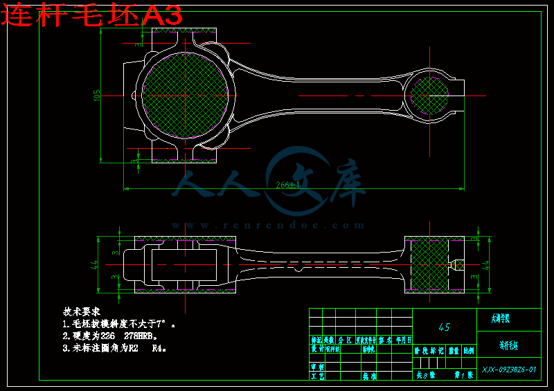
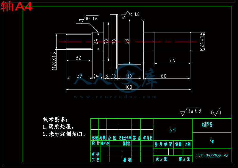
造型.dwg
造型.dwg

连杆工艺工装设计【机械加工夹具资料】【9张CAD图纸+毕业论文】【答辩通过】

收藏

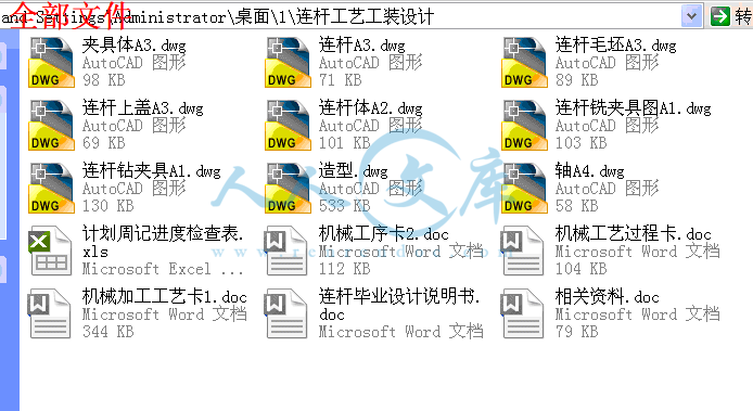
压缩包内文档预览:
预览图
编号:445412    类型:共享资源    大小:1.27MB    格式:RAR    上传时间:2015-07-01 上传人:好资料QQ****51605 IP属地:江苏
45
积分
关 键 词:
连杆 工艺 工装 设计 机械 加工 夹具 资料 全套 cad 图纸 毕业论文 答辩 通过
资源描述:

摘 要

连杆是柴油机的主要传动件之一,本文主要论述了连杆的加工工艺及其夹具设计。连杆的尺寸精度、形状精度以及位置精度的要求都很高,而连杆的刚性比较差,容易产生变形,因此在安排工艺过程时,就需要把各主要表面的粗精加工工序分开。逐步减少加工余量、切削力及内应力的作用,并修正加工后的变形,就能最后达到零件的技术要求。

机械加工工艺是企业上品种、上质量、上水平,加速产品更新,提高经济效益的技术保障。然而夹具又是制造系统的重要部分,工艺对夹具的要求也会提高,专用夹具、成组夹具、组合夹具和随行夹具都朝着柔性化、自动化、标准化、通用化和高效化方向发展以满足加工要求。所以对机械的加工工艺及夹具设计具有十分重要的意义。


关键词: 连杆;加工工艺;夹具设计


Abstract


The connecting rod is one of the main driving medium of diesel engine, this text expounds mainly the machining technology and the design of clamping device of the connecting rod. The precision of size, the precision of profile and the precision of position , of the connecting rod is demanded highly , and the rigidity of the connecting rod is not enough, easy to deform, so arranging the craft course, need to separate the each main and superficial thick finish machining process. Reduce the function of processing the surplus , cutting force and internal stress progressively , revise the deformation after processing, can reach the specification requirement for the part finally


Keywords:  connecting rod;deformination;processing technology;design of

clamping device


目录

摘 要III

AbstractIV

绪论1

1 零件的造型2

1.1零件造型软件介绍2

1.2零件造型过程2

2 零件的分析7

2.1 零件的作用7

2.2 零件的工艺分析7

2.2.1 零件图样分析7

2.2.2 工艺分析7

3 工艺规程设计9

3.1 确定毛坯的制造形式9

3.2 定位基准的选择9

3.2.1 粗基准的选择9

3.2.2 精基准的选择10

3.3 拟定工艺路线10

3.3.1 工艺路线方案一11

3.3.2 工艺路线方案二11

3.4 工艺方案的比较与分析12

3.5 机械加工余量、工序尺寸及毛坯尺寸的确定14

3.5.1 大小头两端表面14

3.5.2 99±0.01mm的两侧面14

3.5.3 内孔Φ25mm14

3.5.4 内孔Φ50mm14

3.5.5 油孔Φ5mm14

3.5.6 油孔Φ1.5mm14

3.5.7 油孔Φ4mm15

3.5.8 油孔Φ8mm15

3.5.9 螺栓孔Φ12.22mm15

3.5.10 螺栓孔Φ13mm15

3.5.11 锪孔Φ20mm15

3.5.12 镗孔Φ58±0.05mm15

3.5.13 镗孔Φ26±0.05mm16

3.5.14 镗孔Φ65.5mm16

3.5.15 镗孔Φ29.5mm16

3.5.16 铣连杆上盖5mm×8mm斜槽16

3.5.17 铣连杆体5mm×8mm斜槽16

3.6 确定切削用量及工时定额16

4 专用夹具设计45

4.1 问题的提出45

4.2 夹具设计45

4.2.1 定位基准的选择45

4.3 切削力及夹紧力计算45

4.2.2 定位误差分析46

5 存在的问题与展望47

5.1 存在的问题47

5.2 展望47

47

毕业设计小结48

致 谢49

参考文献50


绪论

机械的加工工艺及夹具设计是在完成了大学的全部课程之后,进行的一次理论联系实际的综合运用,使我对专业知识、技能有了进一步的提高,为以后从事专业技术的工作打下基础。机械加工工艺是实现产品设计,保证产品质量、节约能源、降低成本的重要手段,是企业进行生产准备,计划调度、加工操作、生产安全、技术检测和健全劳动组织的重要依据,也是企业上品种、上质量、上水平,加速产品更新,提高经济效益的技术保证。然而夹具又是制造系统的重要组成部分,不论是传统制造,还是现代制造系统,夹具都是十分重要的。因此,好的夹具设计可以提高产品劳动生产率,保证和提高加工精度,降低生产成本等,还可以扩大机床的使用范围,从而使产品在保证精度的前提下提高效率、降低成本。当今激烈的市场竞争和企业信息化的要求,企业对夹具的设计及制造提出了更高的要求。所以对机械的加工工艺及夹具设计具有十分重要的意义。

   夹具从产生到现在,大约可以分为三个阶段:第一个阶段主要表现在夹具与人的结合上,这是夹具主要是作为人的单纯的辅助工具,是加工过程加速和趋于完善;第二阶段,夹具成为人与机床之间的桥梁,夹具的机能发生变化,它主要用于工件的定位和夹紧。人们越来越认识到,夹具与操作人员改进工作及机床性能的提高有着密切的关系,所以对夹具引起了重视;第三阶段表现为夹具与机床的结合,夹具作为机床的一部分,成为机械加工中不可缺少的工艺装备。

内容简介:
表2.3 机械加工工艺卡(工厂)机械加工工艺卡片产品型号零(部)件图号共 页产品名称零(部)件名称连杆第 页材料牌号45毛坯种类模锻件毛坯外形尺寸26610544mm每毛坯件数1每台件数1备注工 序装 夹工步工序内容同时加工零件数切削用量设备名称及编号工艺装备名称及编号技 术 等 级工时定额背吃刀量(mm)切削 速度m/min每分钟转数进给量(mm)夹具刀具量具单件准终10模锻毛坯成形、切边DM01-120正火处理30探伤40清除毛刺、飞边50划线6011粗铣连杆大小两平面上表面2.533.416980mm/minX5030AXZ01-1高速刚圆柱形铣刀游标卡尺1.98编制(日期)审核(日期)会签(日期)标记处数更改文件号签字日期标记处数更改文件号签字日期表2.3 机械加工工艺卡(工厂)机械加工工艺卡片产品型号零(部)件图号共 页产品名称零(部)件名称连杆第 页材料牌号45毛坯种类模锻件毛坯外形尺寸26610544mm每毛坯件数1每台件数1备注工 序装 夹工步工序内容同时加工零件数切削用量设备名称及编号工艺装备名称及编号技 术 等 级工时定额背吃刀量(mm)切削 速度m/min每分钟转数进给量(mm)夹具刀具量具单件准终2粗铣连杆大小两平面下表面2.533.416980mm/minX5030AXZ01-1高速刚圆柱形铣刀游标卡尺1.987011磨大平面,0.52415000.029M7130MZ01-1砂轮卡板0.322翻转磨另一个大平面0.52415000.0290.380重新划大小头孔线9011钻孔23mm11.526.374200.4Z3050ZZ01-123麻花钻塞规0.432扩24.8mm孔0.920.64265124.8麻花钻0.17编制(日期)审核(日期)会签(日期)标记处数更改文件号签字日期标记处数更改文件号签字日期表2.3 机械加工工艺卡(工厂)机械加工工艺卡片产品型号零(部)件图号共 页产品名称零(部)件名称连杆第 页材料牌号45毛坯种类模锻件毛坯外形尺寸26610544mm每毛坯件数1每台件数1备注工 序装 夹工步工序内容同时加工零件数切削用量设备名称及编号工艺装备名称及编号技 术 等 级工时定额背吃刀量(mm)切削 速度m/min每分钟转数进给量(mm)夹具刀具量具单件准终3铰25孔0.110.361321.2Z3050ZZ01-225麻花钻塞规0.421钻孔25mm12.532.974200.425麻花钻0.462钻孔48mm11.525.621700.648麻花钻0.653扩49.75mm孔0.87520.62132149.75麻花钻0.434铰50孔0.12510.52671.250麻花钻0.7810011镗孔至25.8mm0.481.0110000.3T68TZ01-1镗刀塞规0.23编制(日期)审核(日期)会签(日期)标记处数更改文件号签字日期标记处数更改文件号签字日期表2.3 机械加工工艺卡(工厂)机械加工工艺卡片产品型号零(部)件图号共 页产品名称零(部)件名称连杆第 页材料牌号45毛坯种类模锻件毛坯外形尺寸26610544mm每毛坯件数1每台件数1备注工 序装 夹工步工序内容同时加工零件数切削用量设备名称及编号工艺装备名称及编号技 术 等 级工时定额背吃刀量(mm)切削 速度m/min每分钟转数进给量(mm)夹具刀具量具单件准终21镗26mm孔0.18.161001.2T68TZ01-1镗刀塞规0.5331镗孔至54mm2135.658000.3T68TZ01-2镗刀游标卡尺0.292镗孔至56mm1140.678000.30.293镗孔至57.5mm0.75113.756300.20.374镗58mm孔0.1259.65531.20.9911011铣尺寸99 0.01mm两侧面333.416980mm/minX6132XZ01-2圆盘镶齿铣刀游标卡尺3.05编制(日期)审核(日期)会签(日期)标记处数更改文件号签字日期标记处数更改文件号签字日期表2.3 机械加工工艺卡(工厂)机械加工工艺卡片产品型号零(部)件图号共 页产品名称零(部)件名称连杆第 页材料牌号45毛坯种类模锻件毛坯外形尺寸26610544mm每毛坯件数1每台件数1备注工 序装 夹工步工序内容同时加工零件数切削用量设备名称及编号工艺装备名称及编号技 术 等 级工时定额背吃刀量(mm)切削 速度m/min每分钟转数进给量(mm)夹具刀具量具单件准终12011按线切开连杆13011钻孔11.8mm5.924.826700.4Z3050ZZ01-311.8麻花钻塞规游标卡尺0.152铰12孔0.19.992651.212麻花钻0.1321精铰孔至12.220.1110.172651.212.22麻花钻0.1231扩12.8mm孔0.410.65265112.8 麻花钻塞规0.122铰13mm孔0.110.812651.213麻花钻0.13编制(日期)审核(日期)会签(日期)标记处数更改文件号签字日期标记处数更改文件号签字日期表2.3 机械加工工艺卡(工厂)机械加工工艺卡片产品型号零(部)件图号共 页产品名称零(部)件名称连杆第 页材料牌号45毛坯种类模锻件毛坯外形尺寸26610544mm每毛坯件数1每台件数1备注工 序装 夹工步工序内容同时加工零件数切削用量设备名称及编号工艺装备名称及编号技 术 等 级工时定额背吃刀量(mm)切削 速度m/min每分钟转数进给量(mm)夹具刀具量具单件准终41锪孔20mmZ3050ZZ01-320麻花钻塞规0.0214011钻孔11.8mm5.924.826700.4Z3050ZZ01-411.8麻花钻塞规0.142铰12孔0.19.992651.212麻花钻0.121精铰孔至12.220.1110.172651.212.22麻花钻游标卡尺0.1315011精磨两分割面0.12415000.029M7130MZ01-1砂轮卡板0.3816011用螺栓将连杆体和连杆上盖组装成连杆组件编制(日期)审核(日期)会签(日期)标记处数更改文件号签字日期标记处数更改文件号签字日期表2.3 机械加工工艺卡(工厂)机械加工工艺卡片产品型号零(部)件图号共 页产品名称零(部)件名称连杆第 页材料牌号45毛坯种类模锻件毛坯外形尺寸26610544mm每毛坯件数1每台件数1备注工 序装 夹工步工序内容同时加工零件数切削用量设备名称及编号工艺装备名称及编号技 术 等 级工时定额背吃刀量(mm)切削 速度m/min每分钟转数进给量(mm)夹具刀具量具单件准终17011镗孔至29mm1.591.0610000.3T68TZ01-3镗刀塞规0.232精镗29.5mm孔0.259.261001.20.5321镗孔至61mm1.5128.336700.3TZ01-4游标卡尺0.352镗孔至63.5mm;1.25133.596700.30.353镗孔至65mm;0.75136.756700.20.374精细镗65.5mm孔0.2510.90531.20.99编制(日期)审核(日期)会签(日期)标记处数更改文件号签字日期标记处数更改文件号签字日期表2.3 机械加工工艺卡(工厂)机械加工工艺卡片产品型号零(部)件图号共 页产品名称零(部)件名称连杆第 页材料牌号45毛坯种类模锻件毛坯外形尺寸26610544mm每毛坯件数1每台件数1备注工 序装 夹工步工序内容同时加工零件数切削用量设备名称及编号工艺装备名称及编号技 术 等 级工时定额背吃刀量(mm)切削 速度m/min每分钟转数进给量(mm)夹具刀具量具单件准终180拆除连杆体与上盖19011铣连杆上盖5mm8mm斜槽1.533.416980mm/minX6132XZ01-3三面刃铣刀游标卡尺0.222铣连杆体5mm8mm斜槽1.533.416980mm/minXZ01-40.220011钻孔4.82.42217000.12Z3050ZZ01-54.8麻花钻塞规、游标卡尺0.152铰5孔0.18.325301.25麻花钻0.043钻油孔1.5mm0.758.0117000.121.5 麻花钻0.12编制(日期)审核(日期)会签(日期)标记处数更改文件号签字日期标记处数更改文件号签字日期表2.3 机械加工工艺卡(工厂)机械加工工艺卡片产品型号零(部)件图号共 页产品名称零(部)件名称连杆第 页材料牌号45毛坯种类模锻件毛坯外形尺寸26610544mm每毛坯件数1每台件数1备注工 序装 夹工步工序内容同时加工零件数切削用量设备名称及编号工艺装备名称及编号技 术 等 级工时定额背吃刀量(mm)切削 速度m/min每分钟转数进给量(mm)夹具刀具量具单件准终21钻孔3.91.9520.8217000.15Z3050ZZ01-63.9麻花钻塞规、游标卡尺0.072铰4mm孔0.058.426701.24麻花钻0.023钻孔7.8mm0.1920.828500.277.8麻花钻0.064铰8mm0.18.423351.28麻花钻0.07210去毛刺,按规定去重量220刮研螺栓孔端面编制(日期)审核(日期)会签(日期)标记处数更改文件号签字日期标记处数更改文件号签字日期表2.3 机械加工工艺卡(工厂)机械加工工艺卡片产品型号零(部)件图号共 页产品名称零(部)件名称连杆第 页材料牌号45毛坯种类模锻件毛坯外形尺寸26610544mm每毛坯件数1每台件数1备注工 序装 夹工步工序内容同时加工零件数切削用量设备名称及编号工艺装备名称及编号技 术 等 级工时定额背吃刀量(mm)切削 速度m/min每分钟转数进给量(mm)夹具刀具量具单件准终230检查各部尺寸及精度240组装入库编制(日期)审核(日期)会签(日期)标记处数更改文件号签字日期标记处数更改文件号签字日期表2.4 机械加工工序卡(工厂)机械加工工序卡产品型号零件图号产品名称零件名称共1 页第1 页车间 工序号工序名称材料牌号金工110铣削45毛坯种类毛坯外形尺寸每毛坯可制作数每台件数锻件266105441设备名称设备型号设备编号同时加工件数铣床X6132夹具编号夹具名称切削液XZ01-1铣夹具工位夹具编号工位器具名称工序工时准终单件工步号工步名称工艺装备主轴转速(r/min)切削速度(m/min)进给量(mm)背吃刀量(mm)进给次数工时/min机动单件描图1铣尺寸99 0.01mm两侧面16933.480mm/min313.05描校底图号装订号设计 (日期)审核 (日期)标准化 (日期)会签 (日期)标记处数更改文件号签字日期标记处数更改文件号签字日期表2.4 机械加工工序卡(工厂)机械加工工序卡产品型号零件图号产品名称零件名称共1 页第1 页车间 工序号工序名称材料牌号金工170镗削45毛坯种类毛坯外形尺寸每毛坯可制作数每台件数锻件266105441设备名称设备型号设备编号同时加工件数铣床T68夹具编号夹具名称切削液TZ01-3镗夹具工位夹具编号工位器具名称工序工时准终单件工步号工步名称工艺装备主轴转速(r/min)切削速度(m/min)进给量(mm)背吃刀量(mm)进给次数工时/min机动单件描图1镗孔至29mm91.0610000.31.510.232精镗29.5mm孔9.261001.20.2510.53描校3镗孔至61mm128.336700.31.510.354镗孔至63.5mm;133.596700.31.2510.35底图号5镗孔至65mm;136.756700.20.7510.376精细镗65.5mm孔10.90531.20.2510.99装订号设计 (日期)审核 (日期)标准化 (日期)会签 (日期)标记处数更改文件号签字日期标记处数更改文件号签字日期表2.2 机械加工工艺过程卡机械加工工艺过程卡片产品型号零件图号产品名称零件名称连杆共2 页第 1 页材料牌号45毛坯种类模锻件毛坯外形尺寸26610544mm每毛坯可制作数1每台件数 1备注工序号工序 名称工序内容车间工段设备工艺装备工时/min10模锻模锻毛坯成形、切边锻工100KN摩擦压力机DM01-220热处理正火处理热处理30探伤探伤质检40质检清除毛刺、飞边钳工50钳工划线钳工60铣削粗铣连杆大小两平面金工X5030AXZ01-13.9670磨削磨大平面,翻转磨另一个大平面,保证厚度尺寸为38mm金工M7130MZ01-10.6描图80钳工重新划大小头孔线钳工90钻削钻、扩大小头孔,大头孔尺寸为 50mm,小头孔尺寸为 25mm金工Z3050ZZ01-13.32描校100镗削粗镗大、小头孔,大头孔的尺寸为580.05mm,小头孔尺寸为26 0.05mm金工T68TZ01-12.7110铣削铣尺寸99 0.01mm两侧面,保证对称金工X6132XZ01-13.05底图号120铣工按线切开连杆金工X6132XZ01-1130钻削钻油孔铣连杆上盖分割面,钻连杆两螺栓孔12mm保证中心距820.0175,精镗孔12.22mm和扩孔 13mm,孔深15mm。锪220mm孔金工Z3050ZZ01-10.67装订号设计 (日期)审核 (日期)标准化 (日期)会签 (日期)标记处数更改文件号签字日期标记处数更改文件号签字日期表2.2 机械加工工艺过程卡机械加工工艺过程卡片产品型号零件图号产品名称零件名称连杆共2 页第2 页材料牌号45毛坯种类模锻件毛坯外形尺寸26610544mm每毛坯可制作数1每台件数 1备注工序号工序 名称工序内容车间工段设备工艺装备工时/min140钻削铣连杆体分割面,钻连杆两螺栓孔12mm保证中心距82 0.0175,精铰孔12.22mm。锪平面R7mm,保证尺寸24 0.26mm 金工Z3050ZZ01-10.37150磨削精磨两分割面金工0.38160钳工用螺栓将连杆体和连杆上盖组装成连杆组件钳工170镗削半精镗大、小头孔;精镗大、小头孔至图样尺寸,中心距为1900.08mm清除毛刺、飞边金工T68TZ01-12.82180钳工拆除连杆体与上盖钳工190铣削铣连杆上盖5mm8mm斜槽,铣连杆体5mm8mm斜槽金工X6132XZ01-20.4200钻削钻连杆体大头油孔 5mm、1.5mm,小头油孔 4mm、 8mm金工Z3050ZZ01-10.53描图210钳工去毛刺,按规定去重量钳工220钳工刮研螺栓孔端面钳工描校230质检检查各部尺寸及精度质检240入库组装入库底图号装订号设计 (日期)审核 (日期)标准化 (日期)会签 (日期)标记处数更改文件号签字日期标记处数更改文件号签字日期编号无锡太湖学院毕业设计(论文)相关资料题目: 连杆工艺工装设计 信机 系 机械工程及自动化专业学 号: 0923826学生姓名: 祝祥竣 指导教师: 鲍虹苏 (职称:高工 ) (职称: )2013年5月25日 目 录一、毕业设计(论文)开题报告二、毕业设计(论文)外文资料翻译及原文三、学生“毕业论文(论文)计划、进度、检查及落实表”四、实习鉴定表无锡太湖学院毕业设计(论文)开题报告题目: 连杆工艺工装设计 信机 系 机械工程及自动化 专业学 号: 0923826 学生姓名: 祝祥竣 指导教师: 鲍虹苏(职称:高工 ) (职称: )2012年11月25日课题来源连杆作为最普遍的传动机构,在生活工作中的运用越来越多,连杆在工作中,除承受燃烧室燃气产生的压力外,还要承受纵向和横向的惯性力。因此,连杆在一个复杂的应力状态下工作。它既受交变的拉压应力、又受弯曲应力。科学依据(包括课题的科学意义;国内外研究概况、水平和发展趋势;应用前景等)连杆的作用是将活塞承受的力传给曲轴,并使活塞的往复运动转变为曲轴的旋转运动。连杆由连杆体、连杆盖、连杆螺栓和连杆轴瓦等零件组成,连杆体与连杆盖分为连杆小头、杆身和连杆大头。连杆小头用来安装活塞销,以连接活塞。杆身通常做成“工”或“H”形断面,以求在满足强度和刚度要求的前提下减少质量。连杆大头与曲轴的连杆轴颈相连。一般做成分开式,与杆身切开的一半称为连杆盖,二者靠连杆螺栓连接为一体。连杆轴瓦 安装在连杆大头孔座中,与曲轴上的连杆轴颈装和在一起,是发动机中最重要的配合副之一。常用的减磨合金主要有白合金、铜铅合金和铝基合金。研究内容涉及连杆的工艺工装,总体方案的设计、结构形成、结构参数的设计要求如下:阅读外文资料,翻译与所学专业或课题相关的外文文献3000字左右,语句通顺、流畅、准确。了解立式袋装机装置的工作原理。根据加工产品的具体结构和要求,拟定分析设备设计方案。绘制整套的零件图、装配图、各零件的精度配合。用CAD进行造型。撰写论文,要求符合本科论文的格式要求、语言简洁、流畅、层次分明。上机的时数不得少于200个小时,整个毕业设计过程的技术工作要严谨、灵活、工作要有主动性、计算方法、计算程序、计算结果、结论要正确。拟采取的研究方法、技术路线、实验方案及可行性分析连杆的工艺工装设计首先对各个零件进行设计和造型,最后装配成连杆实体,进而进行工艺分析,零件的材料及机械性能要求,零件的结构形状与外形尺寸,它在很大程度上决定采用毛坯制造方法的经济性,充分考虑利用新工艺、新材料、新技术的可能性,还有基准面的选择,最后确定工艺路线,确定了两个工艺路线,最后根据生产实际综合确定一工艺路线。另外再进行夹具的设计。 研究计划及预期成果1.明确连杆的预期达到的性能指标。2.总体方案的设计,可行性分析。3.连杆的初步设计,总体机构的设计,各部分的参数设计。4.强度验算,分析验证,优化设计。5.完成二维图和三维的绘制。6.完成总体的装配图。7.完成实际说明书。特色或创新之处 本此的连杆工艺工装设计,综合考虑了各方面因素,在生产运行过程中更加的平稳,承载能力得到了进一步加强,润滑好,磨损小,加工制造更容易。在改变运动的传递方向,扩大行程,实现增力和远程传动等方面更容易。已具备的条件和尚需解决的问题具备的条件:各种资料比较齐全,方便查阅。尚需解决的问题: 连杆的结构分析。 连杆的CAD三维建模有难度。 各种零件的材料选择尚需解决。指导教师意见 指导教师签名: 年 月 日教研室(学科组、研究所)意见 教研室主任签名: 年 月 日系意见 主管领导签名: 年 月 日Manufacturing Engineering and TechnologyMachining1. The machinability of a material usually defined in terms of four factors: 1)、 Surface finish and integrity of the machined part; 2)、 Tool life obtained; 3)、 Force and power requirements; 4)、 Chip control. Thus, good machinability good surface finish and integrity, long tool life, and low force and power requirements. As for chip control, long and thin (stringy) cured chips, if not broken up, can severely interfere with the cutting operation by becoming entangled in the cutting zone.Because of the complex nature of cutting operations, it is difficult to establish relationships that quantitatively define the machinability of a material. In manufacturing plants, tool life and surface roughness are generally considered to be the most important factors in machinability. Although not used much any more, approximate machinability ratings are available in the example below.2. Machinability Of SteelsBecause steels are among the most important engineering materials (as noted in Chapter 5), their machinability has been studied extensively. The machinability of steels has been mainly improved by adding lead and sulfur to obtain so-called free-machining steels.Resulfurized and Rephosphorized steels. Sulfur in steels forms manganese sulfide inclusions (second-phase particles), which act as stress raisers in the primary shear zone. As a result, the chips produced break up easily and are small; this improves machinability. The size, shape, distribution, and concentration of these inclusions significantly influence machinability. Elements such as tellurium and selenium, which are both chemically similar to sulfur, act as inclusion modifiers in resulfurized steels.Phosphorus in steels has two major effects. It strengthens the ferrite, causing increased hardness. Harder steels result in better chip formation and surface finish. Note that soft steels can be difficult to machine, with built-up edge formation and poor surface finish. The second effect is that increased hardness causes the formation of short chips instead of continuous stringy ones, thereby improving machinability.Leaded Steels. A high percentage of lead in steels solidifies at the tip of manganese sulfide inclusions. In non-resulfurized grades of steel, lead takes the form of dispersed fine particles. Lead is insoluble in iron, copper, and aluminum and their alloys. Because of its low shear strength, therefore, lead acts as a solid lubricant and is smeared over the tool-chip interface during cutting. This behavior has been verified by the presence of high concentrations of lead on the tool-side face of chips when machining leaded steels.When the temperature is sufficiently high-for instance, at high cutting speeds and feeds the lead melts directly in front of the tool, acting as a liquid lubricant. In addition to this effect, lead lowers the shear stress in the primary shear zone, reducing cutting forces and power consumption. Lead can be used in every grade of steel, such as 10xx, 11xx, 12xx, 41xx, etc. Leaded steels are identified by the letter L between the second and third numerals (for example, 10L45). (Note that in stainless steels, similar use of the letter L means “low carbon,” a condition that improves their corrosion resistance.)However, because lead is a well-known toxin and a pollutant, there are serious environmental concerns about its use in steels (estimated at 4500 tons of lead consumption every year in the production of steels). Consequently, there is a continuing trend toward eliminating the use of lead in steels (lead-free steels). Bismuth and tin are now being investigated as possible substitutes for lead in steels.Calcium-Deoxidized Steels. An important development is calcium-deoxidized steels, in which oxide flakes of calcium silicates (CaSo) are formed. These flakes, in turn, reduce the strength of the secondary shear zone, decreasing tool-chip interface and wear. Temperature is correspondingly reduced. Consequently, these steels produce less crater wear, especially at high cutting speeds.Stainless Steels. Austenitic (300 series) steels are generally difficult to machine. Chatter can be a problem, necessitating machine tools with high stiffness. However, ferritic stainless steels (also 300 series) have good machinability. Martensitic (400 series) steels are abrasive, tend to form a built-up edge, and require tool materials with high hot hardness and crater-wear resistance. Precipitation-hardening stainless steels are strong and abrasive, requiring hard and abrasion-resistant tool materials.The Effects of Other Elements in Steels on Machinability. The presence of aluminum and silicon in steels is always harmful because these elements combine with oxygen to form aluminum oxide and silicates, which are hard and abrasive. These compounds increase tool wear and reduce machinability. It is essential to produce and use clean steels.Carbon and manganese have various effects on the machinability of steels, depending on their composition. Plain low-carbon steels (less than 0.15% C) can produce poor surface finish by forming a built-up edge. Cast steels are more abrasive, although their machinability is similar to that of wrought steels. Tool and die steels are very difficult to machine and usually require annealing prior to machining. Machinability of most steels is improved by cold working, which hardens the material and reduces the tendency for built-up edge formation.Other alloying elements, such as nickel, chromium, molybdenum, and vanadium, which improve the properties of steels, generally reduce machinability. The effect of boron is negligible. Gaseous elements such as hydrogen and nitrogen can have particularly detrimental effects on the properties of steel. Oxygen has been shown to have a strong effect on the aspect ratio of the manganese sulfide inclusions; the higher the oxygen content, the lower the aspect ratio and the higher the machinability.In selecting various elements to improve machinability, we should consider the possible detrimental effects of these elements on the properties and strength of the machined part in service. At elevated temperatures, for example, lead causes embrittlement of steels (liquid-metal embrittlement, hot shortness; see Section 1.4.3), although at room temperature it has no effect on mechanical properties.Sulfur can severely reduce the hot workability of steels, because of the formation of iron sulfide, unless sufficient manganese is present to prevent such formation. At room temperature, the mechanical properties of resulfurized steels depend on the orientation of the deformed manganese sulfide inclusions (anisotropy). Rephosphorized steels are significantly less ductile, and are produced solely to improve machinability.3. Machinability of Various Other Metals Aluminum is generally very easy to machine, although the softer grades tend to form a built-up edge, resulting in poor surface finish. High cutting speeds, high rake angles, and high relief angles are recommended. Wrought aluminum alloys with high silicon content and cast aluminum alloys may be abrasive; they require harder tool materials. Dimensional tolerance control may be a problem in machining aluminum, since it has a high thermal coefficient of expansion and a relatively low elastic modulus.Beryllium is similar to cast irons. Because it is more abrasive and toxic, though, it requires machining in a controlled environment.Cast gray irons are generally machinable but are. Free carbides in castings reduce their machinability and cause tool chipping or fracture, necessitating tools with high toughness. Nodular and malleable irons are machinable with hard tool materials.Cobalt-based alloys are abrasive and highly work-hardening. They require sharp, abrasion-resistant tool materials and low feeds and speeds.Wrought copper can be difficult to machine because of built-up edge formation, although cast copper alloys are easy to machine. Brasses are easy to machine, especially with the addition pf lead (leaded free-machining brass). Bronzes are more difficult to machine than brass.Magnesium is very easy to machine, with good surface finish and prolonged tool life. However care should be exercised because of its high rate of oxidation and the danger of fire (the element is pyrophoric).Molybdenum is ductile and work-hardening, so it can produce poor surface finish. Sharp tools are necessary.Nickel-based alloys are work-hardening, abrasive, and strong at high temperatures. Their machinability is similar to that of stainless steels.Tantalum is very work-hardening, ductile, and soft. It produces a poor surface finish; tool wear is high.Titanium and its alloys have poor thermal conductivity (indeed, the lowest of all metals), causing significant temperature rise and built-up edge; they can be difficult to machine.Tungsten is brittle, strong, and very abrasive, so its machinability is low, although it greatly improves at elevated temperatures.Zirconium has good machinability. It requires a coolant-type cutting fluid, however, because of the explosion and fire.4. Machinability of Various MaterialsGraphite is abrasive; it requires hard, abrasion-resistant, sharp tools.Thermoplastics generally have low thermal conductivity, low elastic modulus, and low softening temperature. Consequently, machining them requires tools with positive rake angles (to reduce cutting forces), large relief angles, small depths of cut and feed, relatively high speeds, and proper support of the workpiece. Tools should be sharp.External cooling of the cutting zone may be necessary to keep the chips from becoming “gummy” and sticking to the tools. Cooling can usually be achieved with a jet of air, vapor mist, or water-soluble oils. Residual stresses may develop during machining. To relieve these stresses, machined parts can be annealed for a period of time at temperatures ranging from to ( to ), and then cooled slowly and uniformly to room temperature.Thermosetting plastics are brittle and sensitive to thermal gradients during cutting. Their machinability is generally similar to that of thermoplastics.Because of the fibers present, reinforced plastics are very abrasive and are difficult to machine. Fiber tearing, pulling, and edge delamination are significant problems; they can lead to severe reduction in the load-carrying capacity of the component. Furthermore, machining of these materials requires careful removal of machining debris to avoid contact with and inhaling of the fibers.The machinability of ceramics has improved steadily with the development of nanoceramics and with the selection of appropriate processing parameters, such as ductile-regime cutting .Metal-matrix and ceramic-matrix composites can be difficult to machine, depending on the properties of the individual components, i.e., reinforcing or whiskers, as well as the matrix material.5. Thermally Assisted MachiningMetals and alloys that are difficult to machine at room temperature can be machined more easily at elevated temperatures. In thermally assisted machining (hot machining), the source of heata torch, induction coil, high-energy beam (such as laser or electron beam), or plasma arcis forces, (b) increased tool life, (c) use of inexpensive cutting-tool materials, (d) higher material-removal rates, and (e) reduced tendency for vibration and chatter.It may be difficult to heat and maintain a uniform temperature distribution within the workpiece. Also, the original microstructure of the workpiece may be adversely affected by elevated temperatures. Most applications of hot machining are in the turning of high-strength metals and alloys, although experiments are in progress to machine ceramics such as silicon nitride. 6. SUMMARYMachinability is usually defined in terms of surface finish, tool life, force and power requirements, and chip control. Machinability of materials depends not only on their intrinsic properties and microstructure, but also on proper selection and control of process variables. 译文:1.切削加工性一种材料的切削加工性通常从四个方面来定义:(1)、已切削部分的表面光洁度和表面完整性。(2)、刀具的寿命。(3)、切削力和切削的功率需求。(4)、切屑控制。由上述可知,好的切削加工性指的是好的表面光洁度和完整性,长的刀具寿命,低切削力和功率需求。至于切屑控制,细长而卷曲的切屑,如果没有及时清理,就会在切削区缠绕,严重影响切削工序。由于切削工序的复杂性,因此很难建立一个定量确定一种材料切削加工性的关系式。在制造厂里,刀具寿命和表面粗糙度通常被认为是切削加工性中最重要的影响因素。尽管切削性能指数使用的并不多,但基本的切削性能指数在下面的材料中仍然被使用。2.钢的切削加工性因为钢是最重要的工程材料之一(如第5章所示),所以它的切削加工性已经被广泛地研究过。通过加入铅和硫磺,可以使钢的切削加工性得到大幅度地提高。从而得到了所谓的高速切削钢。二次硫化钢和二次磷化钢 硫在钢中形成硫化锰夹杂物(第二相粒子),这些夹杂物在第一剪切区形成应力集中元。其结果是使切屑容易断开而变小,从而改善了切削加工性。这些夹杂物的大小、形状、分布和集中程度显著的影响切削加工性。化学元素如碲和硒,其化学性质与硫类似,在二次硫化钢中起杂质改性作用。钢中的磷有两个主要的作用。第一它加强铁素体,增加硬度。越硬的钢,就会对切屑的形成和表面光洁度越有利。需要注意的是软钢是很难加工的,因为软钢加工容易产生积削瘤而且表面光洁度差。第二个作用是硬度增加会引起短切屑的形成而不是连续细长的切屑的形成,因此提高切削加工性。铅钢 钢中高含量的铅在硫化锰杂质尖端析出。在非二次硫化钢中,铅呈细小而分散的颗粒。铅在铁、铜、铝和它们的合金中是不能溶解的。由于它的低抗剪强度,铅在切削时充当固体润滑剂,被涂在刀具和切屑的分界处。这一特性已经被证实-在切削加工铅钢时,在刀具横向表面的切屑上有高浓度的铅存在。当温度足够高时例如,在高的切削速度和进刀速度下铅在刀具前直接熔化,并且充当液体润滑剂。除了这个作用外,铅还可以降低第一剪切区中的剪应力,减小切削力和降低功率消耗。铅能用于各种型号的钢,例如10XX,11XX,12XX,41XX等等。铅钢由型号中第二和第三数码中的字母L识别(例如,10L45)。(需要注意的是在不锈钢中,字母L指的是低碳,这是提高不锈钢耐腐蚀性的先决条件)。然而,因为铅是众所周知的毒素和污染物,因此在钢的使用中存在着严重的环境隐患(在钢产品中每年大约有4500吨的铅消耗)。于是,消除铅在钢中使用是一个必然的趋势(无铅钢)。铋和锡现正作为最可能替代钢中铅的物质而被人们所研究。脱氧钙钢 一个重要的发展是脱氧钙钢,在脱氧钙钢中可以形成硅酸钙的氧化物片。这些片状物,可以减小第二剪切区中的应力,降低刀具和切屑分界处的摩擦和磨损。温度也相应地降低。于是,这种钢产生更小的月牙洼磨损,特别是在高速切削时更是如此。不锈钢 通常奥氏体钢很难进行切削加工。振动可能是一个问题,这必需要求机床有足够的刚度。然而,铁素体不锈钢有很好的切削加工性。
温馨提示:
1: 本站所有资源如无特殊说明,都需要本地电脑安装OFFICE2007和PDF阅读器。图纸软件为CAD,CAXA,PROE,UG,SolidWorks等.压缩文件请下载最新的WinRAR软件解压。
2: 本站的文档不包含任何第三方提供的附件图纸等,如果需要附件,请联系上传者。文件的所有权益归上传用户所有。
3.本站RAR压缩包中若带图纸,网页内容里面会有图纸预览,若没有图纸预览就没有图纸。
4. 未经权益所有人同意不得将文件中的内容挪作商业或盈利用途。
5. 人人文库网仅提供信息存储空间,仅对用户上传内容的表现方式做保护处理,对用户上传分享的文档内容本身不做任何修改或编辑,并不能对任何下载内容负责。
6. 下载文件中如有侵权或不适当内容,请与我们联系,我们立即纠正。
7. 本站不保证下载资源的准确性、安全性和完整性, 同时也不承担用户因使用这些下载资源对自己和他人造成任何形式的伤害或损失。
提示  人人文库网所有资源均是用户自行上传分享,仅供网友学习交流,未经上传用户书面授权,请勿作他用。
关于本文
本文标题:连杆工艺工装设计【机械加工夹具资料】【9张CAD图纸+毕业论文】【答辩通过】
链接地址:https://www.renrendoc.com/p-445412.html

官方联系方式

2:不支持迅雷下载,请使用浏览器下载   
3:不支持QQ浏览器下载,请用其他浏览器   
4:下载后的文档和图纸-无水印   
5:文档经过压缩,下载后原文更清晰   
关于我们 - 网站声明 - 网站地图 - 资源地图 - 友情链接 - 网站客服 - 联系我们

网站客服QQ:2881952447     

copyright@ 2020-2025  renrendoc.com 人人文库版权所有   联系电话:400-852-1180

备案号:蜀ICP备2022000484号-2       经营许可证: 川B2-20220663       公网安备川公网安备: 51019002004831号

本站为文档C2C交易模式,即用户上传的文档直接被用户下载,本站只是中间服务平台,本站所有文档下载所得的收益归上传人(含作者)所有。人人文库网仅提供信息存储空间,仅对用户上传内容的表现方式做保护处理,对上载内容本身不做任何修改或编辑。若文档所含内容侵犯了您的版权或隐私,请立即通知人人文库网,我们立即给予删除!