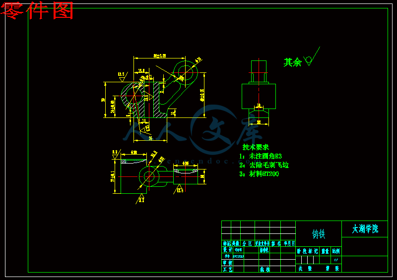
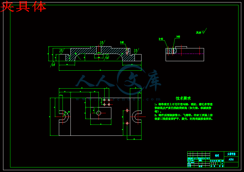
零件图.dwg
零件图.dwg

气门摇臂轴支座零件工艺及工装设计[铣Φ26面夹具]【4张CAD图纸+毕业论文】【答辩通过】

收藏

压缩包内文档预览:
预览图
编号:445705    类型:共享资源    大小:1.36MB    格式:RAR    上传时间:2015-07-02 上传人:好资料QQ****51605 IP属地:江苏
45
积分
关 键 词:
气门 摇臂 支座 零件 工艺 工装 设计 26 全套 cad 图纸 毕业论文 答辩 通过
资源描述:

摘  要

机械加工行业作为一个传统而富有活力的行业,近十几年取得了突飞猛进的发展,在新经济时代,行业呈现了新的发展趋势,由此对其它的质量,性能要求有了新的变化。现在机械加工行业发生着结构性变化,工艺工装的设计与改良已成为企业生存和发展的必要条件,工艺工装的设计与改良直接影响加工产品的质量与性能。  

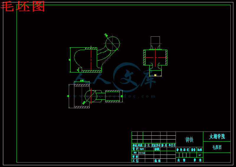
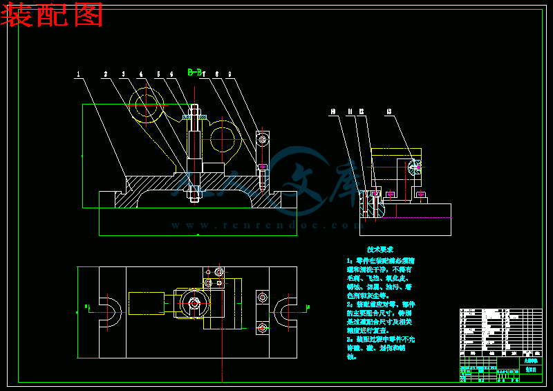
本文首先介绍了气门摇臂轴支座的作用和工艺分析,其次确定毛坯尺寸,然后进行了工艺规程设计,最后进行夹具设计。此次设计是对气门摇臂轴支座的加工工艺和夹具设计,其零件为铸件,具有体积小,零件结构简单的特点,由于面比孔易加工,在制定工艺规程时,就先加工面,再以面为基准来加工其它,其中各工序夹具都采用专用夹具,其机构设计简单,方便且能满足要求。


关键词:气门摇臂轴支座;工艺分析 ;工艺规程设计 ;夹具设计


Abstract


Machining industry ,as a traditional and vibrant industry, has been rapidly developed for a few past decades. In the new economic area,the industry presented a new development trend,and the trends also changes the quality and the performance of the production in some new abstracts. Machining industry is now taking place in structural changes, process design and improvement of equipment has become the necessary conditions of the enterprise survival and development, process equipment design and improved products directly affect the quality and performance.

  This article introduces the role and process analysis of the valve rocker arm bearing support,followed by determining blank size, and then proceed to order the design process, the final fixture design. What will be disgned is The machining process and fixture design of the Valve Rocker Arm Bearing support,which has the chatacteristics of three abstrcat.its components for castings, with a small size, simple structure and the characteristics of parts,because the surface is easier than the easy processing, point of order in the development process, the surface on the first processing , and then to surface as a benchmark to other processing, including the processes used special fixture, and its design is simple, convenient and can meet the requirements.


Key words: JPEG; discrete cosine transform; MATLAB; graphical user interface


目  录

摘  要III

AbstractIV

目  录V

1 绪论1

1.1本课题的研究内容和意义1

1.2国内外的发展概况1

1.3本课题应达到的要求2

2 气门摇臂轴支座主要结构的机械设计3

2.1.零件的工艺分析及生产类型的确定3

2.1.1零件的作用3

2.1.2 零件的工艺分析3

2.1.3 确定零件的生产类型4

2.2 选择毛坯种类,绘制毛坯图5

2.2.1 选择毛坯种类5

2.2.2 确定毛坯尺寸及机械加工总余量5

2.2.3 设计毛坯图6

2.2.4 绘制毛坯图6

2.3 选择加工方法,制定工艺路线7

2.3.1 定位基准的选择7

2.3.2 零件的表面加工方法的选择7

2.3.3加工阶段的划分8

2.3.4工序的集中与分散8

2.3.5工序顺序的安排8

2.3.6 确定工艺路线9

2.3.7 加工设备及工艺装备选择10

2.3.8工序间加工余量的确定11

2.3.9切削用量以及基本时间定额的确定12

3 气门摇臂轴支座零件专用夹具的设计23

3.1 确定夹具的结构方案23

3.1.1 确定定位方案,选择定位元件23

3.1.2 确定导向装置24

3.1.3 确定夹紧机构25

3.1.4 确定辅助定位装置25

3.2 设计夹具体26

3.3 在夹具装配图上标注尺寸、配合及技术要求26

4总结与展望28

致 谢29

参考文献30


1 绪论

1.1本课题的研究内容和意义

本次设计是在我们学完了大学的全部基础课,技术基础课以及专业课之后而进行。此次的设计是对大学期间所学各课程及相关的应用绘图软件的一次深入的综合性的总复习,也是一次理论联系实际的训练。其目的在于:

1.巩固我们在大学里所学的知识,也是对以前所学知识的综合性的检验;

2.加强我们查阅资料的能力,熟悉有关资料;

3.树立正确的设计思想,掌握设计方法,培养我们的实际工作能力;

4.通过对气门摇臂轴支座的机械制造工艺设计,使我们在机械制造工艺规程设计,工艺方案论证,机械加工余量计算,工艺尺寸的确定,编写技术文件及查阅技术文献等各个方面受到一次综合性的训练。初步具备设计一个中等复杂程度零件的工艺规程的能力。

5.能根据被加工零件的技术要求,运用夹具设计的基本原理和方法,学会拟定夹具设计方案,完成夹具结构设计,初步具备设计出高效,省力,经济合理并能保证加工质量的专用夹具的能力。

6.通过零件图,装配图绘制,使我们对于AutoCAD绘图软件的使用能得到进一步的提高。

内容简介:
编号无锡太湖学院毕业设计(论文)相关资料题目: 摇臂零件工艺及工装设计 信机 系 机械工程及自动化专业学 号: 0923140学生姓名: 司舒晖 指导教师: 许文(职称:副教授) 2013年5月25日目 录一、毕业设计(论文)开题报告二、毕业设计(论文)外文资料翻译及原文三、学生“毕业论文(论文)计划、进度、检查及落实表”四、实习鉴定表无锡太湖学院毕业设计(论文)开题报告题目: 摇臂零件工艺及工装设计 信机 系 机械工程及自动化 专业学 号: 0923140 学生姓名: 司舒晖 指导教师: 许文 (职称:副教授 ) 2012年11月14日 课题来源自拟题目科学依据(1)课题科学意义随着现代社会进程的加快,柴油机发挥的社会作用不可估量,特别是在社会工业化之后,柴油机作为动力内燃机的一种,在社会的各个领域无处不在,为社会创造着巨大的效益。在这领域中,柴油机所发挥的作用也是不尽相同,所以根据作用的需要,柴油机也被设计出了很多种型号,各种型号功率不同,发挥的作用大小也就不一样,创造出的价值也不一样。但是柴油机的污染排放也是一个不小的社会问题,随着社会的发展,人类对生活质量要求的提高,而高污染排放的柴油机必定不能满足人类的这一生活需求,但是柴油机已经是社会发展不可缺少的一个重要零部分,彻底取代柴油机在目前的技术条件下似乎还不太可能。(2)研究状况及其发展前景:随着社会的需要,柴油机生产数量将不断的增长,而气门摇臂轴支座是柴油机上不可或缺的零件,也就是意味着气门摇臂轴支座的生产数量将是与日俱增,为了创造出更大的效益,设计出轻便,经久耐用,便于生产的气门摇臂轴支座这一零件是很有必要的。柴油机具有热效率高的显著优点,其应用范围越来越广。随着强化程度的提高,柴油机单位功率的重量也显著降低。为了节能,各国都在注重改善燃烧过程,研究燃用低质燃油和非石油制品燃料。此外,降低摩擦损失、广泛采用废气涡轮增压并提高增压度、进一步轻量化、高速化、低油耗、低噪声和低污染,都是柴油机的重要发展方向。研究内容了解气门摇臂零件的工作原理,国内外的研究发展现状; 完成气门摇臂零件的总体方案设计; 完成有关零部件的选型计算、结构强度校核; 熟练掌握计算机CAD绘图软件,并绘制装配图和零件图纸,折合A0不少于2.5张; 完成说明书的撰写,并且翻译外文资料1篇。拟采取的研究方法、技术路线、实验方案及可行性分析1)技术路线首先根据气门摇臂零件的特殊性对其造型等方面的设计需求进行分析,从整体上把握其设计原则;然后对不同的功能区域进行单独的研究分析,总结出符合工程学要求的设计理论;最后将整体的设计分析和每一部分的设计相结合,寻找有效的结合点并进行统一协调,最终设计出高质量、高档次的产品。(2)研究方法 测试出气门摇臂各零件的尺寸、刚度,获得大量的实验数据。 对实验数据进行分析处理,为建立气门摇臂力学模型与分析作了必要的准备。(3)实验方案 确定具体设计方案:零件的工艺分析及生产类型的确定,零件的工艺分析研究计划及预期成果(1)研究计划:2012年10月28日-2012年11月16日:学习并翻译一篇与毕业设计相关的英文材料2012年11月20日-2013年1月20日:按照任务书要求查阅论文相关参考资料,填写毕业设计开题报告书。2013年1月25日-2013年2月10日:填写毕业实习报告。2013年2月20日-2013年3月10日:按照要求修改毕业设计开题报告。2013年3月19日-2013年3月30日:气门摇臂轴支座铣18孔端面的夹具结构设计。2013年4月1日-2013年4月25日:CAD绘图。2013年4月26日-2013年5月21日:毕业论文撰写和修改工作。(2)预期成果:我国市场前景广阔,产品质量性能逐渐满足要求,因此产品的发展必须由单纯的追求技术上的完善,转向产品外观质量的提高,放到与技术改进放到同等重要的位置,通过本课题的研究,产品必定以合理的色彩以及人性化的结构方式提高自己的附加值,吸引到更多地客户,加大自己产品的市场占有率,提高在行业中的竞争力。特色或创新之处1通用性好,气门摇臂轴支座铣18孔端面在设计过程中,考略到通用性,因此留有余地,因此除搬运外,还可以焊接喷漆等。2工作效率,提高了劳动生产效率,同时也降低了成本。已具备的条件和尚需解决的问题(1).夹具的构造应与其用途和生产规模相适应,正确处理好质量、效率、方便性与经济性四者的关系。 (2).保证使用方便,要便于装卸、便于夹紧、便于测量、便于观察、便于排屑排液、便于安装运输,保证安全第一。 (3).注意结构工艺,对加工、装配、维修通盘考虑,降低成本。指导教师意见 指导教师签名:年 月 日教研室(学科组、研究所)意见 教研室主任签名: 年 月 日系意见 主管领导签名: 年 月 日英文原文Experimental investigation of laser surface textured parallel thrust bearingsPerformance enhancements by laser surface texturing (LST) of parallel-thrust bearings is experimentally investigated. Testresults are compared with a theoretical model and good correlation is found over the relevant operating conditions. A compari-son of the performance of unidirectional and bi-directional partial-LST bearings with that of a baseline, untextured bearing ispresented showing the benets of LST in terms of increased clearance and reduced friction.KEY WORDS: uid lm bearings, slider bearings, surface texturing1. IntroductionThe classical theory of hydrodynamic lubrication yields linear (Couette) velocity distribution with zero pressure gradients between smooth parallel surfaces under steady-state sliding. This results in an unstable hydrodynamic lm that would collapse under any external force acting normal to the surfaces. However, experience shows that stable lubricating lms can develop between parallel sliding surfaces, generallybecause of some mechanism that relaxes one or more of the assumptions of the classical theory.A stable uid lm with sucient load-carrying capacity in parallel sliding surfaces can be obtained, for example, with macro or micro surface structure of dierent types. These include waviness 1 and protruding microasperities 24. A good literature review on the subject can be found in Ref. 5. More recently, laser surface texturing (LST) 68, as well as inlet roughening by longitudinal or transverse grooves 9 were suggested to provide load capacity in parallel sliding. The inlet roughness concept of Tonder 9 is based on eective clearance reduction in the slidingdirection and in this respect it is identical to the par- tial-LST concept described in ref. 10 for generating hydrostatic eect in high-pressure mechanical seals.Very recently Wang et al. 11 demonstrated experimentally a doubling of the load-carrying capacity for the surface- texture design by reactive ion etching of SiC parallel-thrust bearings sliding in water. These simple parallel thrust bearings are usually found in seal-less pumps where the pumped uid is used as the lubricant for the bearings. Due to the parallel sliding their performance is poorer than more sophisticated tapered or stepped bearings. Brizmer et al. 12 demon-strated the potential of laser surface texturing in the form of regular micro-dimples for providing load-carrying capacity with parallel-thrust bearings. A model of a textured parallel slider was developed and the eect of surface texturing on load-carrying capacitywas analyzed. The optimum parameters of the dimples were found in order to obtain maximum load-carrying capacity. A micro-dimple collective eect was identi-ed that is capable of generating substantial load-carrying capacity, approaching that of optimumconventional thrust bearings. The purpose of the present paper is to investigate experimentally the validity of the model described in Ref. 12 by testing practical thrust bearings and comparing the performance of LST bearings with that of the theoretical predictions and with the performance of standard non-texturedbearings2. BackgroundA cross section of the basic model that was analyzed in Ref. 12 is shown in figure 1. A slider having a width B is partially textured over a portion Bp =B of its width. The textured surface consists of multiple dimples with a diameter,depthand area density Sp. As a result of the hydrodynamic pressure generated by the dimples the sliding surfaces will be separated by a clearancedepending on the sliding velocity U, the uid viscosity l and the external loadIt was found in Ref. 12 that an optimum ratio exists for the parameter that provides maximum dimensionless load-carrying capacity where L isthe bearing length, and this optimum value is hp=1.25. It was further found in Ref. 12 that an optimum value exists for the textured portion a depending onthe bearing aspect ratio L/B. This behavior is shown in gure 2 for a bearing with L/B = 0.75 at various values of the area density Sp. As can be seen in the range of Sp values from 0.18 to 0.72 the optimum a value varies from 0.7 to 0.55, respectively. It can also be seen from gure 2 that for a 0.85 no optimum value exists for Sp and the maximum load W increases with increasing Sp. Hence, the largest area density that can be practically obtained with the laser texturing is desired. It is also interesting to note from gure 2 the advantage of partial-LST (a 1) over the full LST (a = 1) for bearing applications. At Sp= 0.5, for example, the load W at a = 0.6 is about three times higher than its value at a = 1. A full account of this behavior is given in Ref. 12.3. ExperimentalThe tested bearings consist of sintered SiC disks 10 mm thick, having 85 mm outer diameter and 40 mm inner diameter. Each bearing (see gure 3) comprises a at rotor (a) and a six-pad stator (b). The bearings were provided with an original surface nishby lapping to a roughness average Ra= 0.03 lm. Each pad has an aspect ratio of 0.75 when its width is measured along the mean diameter of the stator. The photographs of two partial-LST stators are shown in gure 4 where the textured areas appear as brighter matt surfaces. The rst stator indicated (a) is a unidirectional bearing with the partial-LST adjacent to the leading edge of each pad, similar to the model shown in gure 1. The second stator (b) is a bi-directional version of a partial-LST bearing having two equal textured portions, a/2, on each of the pad ends. The laser texturing parameters were the following; dimple depth, dimple diameter and dimple area density Sp= 0.60.03. These dimple dimensions were obtained with 4 pulses of 30 ns duration and 4 mJ each using a 5 kHz pulsating Nd:YAG laser. The textured portion of the unidirectional bearing was a= 0.73 and that of the bi-directional bearing was a= 0.63. As can be seen from gure 2 both these a values should produce load-carrying capacity vary close to the maximum theoretical value.The test rig is shown schematically in gure 5. Anelectrical motor turns a spindle to which an upper holder of the rotor is attached. A second lower holder of the stator is xed to a housing, which rests on a journal bearing and an axial loading mechanism that can freely move in the axial direction. An arm that presses against a load cell and thereby permits friction torque measurements prevents the free rotation of this housing. Axial loading is provided by means of dead weights on a lever and is measured with a second load cell. A proximity probe that is attached to the lower holder of the stator allows on-line measurements of the clearance change between rotor and stator as the hydrodynamic eects cause axial movement of the housing to which the stator holder is xed. Tap water is supplied by gravity from a large tank to the center of the bearing and the leakage from the bearing is collected and re-circulated. A thermocouple adjacent tothe outer diameter of the bearing allows monitoring of the water temperature as the water exit the bearing. A PC is used to collect and process data on-line. Hence,the instantaneous clearance, friction coecient, bearing speed and exit water temperature can be monitored constantly. The test protocol includes identifying a reference “zero” point for the clearance measurements by rst loading and then unloading a stationary bearing over the full load range. Then the lowest axial load is applied, the water supply valve is opened and the motor turned on. Axial loading is increased by steps of 40 N and each load step is maintained for 5 min following the stabilization of the friction coecient ata steady-state value. The bearing speed and water temperature are monitored throughout the test for any irregularities. The test ends when a maximum axial load of 460 N is reached or if the friction coecient exceeds a value of 0.35. At the end of the last load step the motor and water supply are turned o and the reference for the clearance measurements is rechecked. Tests are performed at two speeds of 1500and 3000 rpm corresponding to average sliding velocities of 4.9 and 9.8 m/s, respectively and each test is repeated at least three times.4. Results and discussionAs a rst step the validity of the theoretical model in Ref. 12 was examined by comparing the theoretical and experimental results of bearing clearance versus bearing load for a unidirectional partial-LST bearing. The results are shown in gure 6 for the two speeds of 1500 and 3000 rpm where the solid and dashed lines correspond to the model and experiment, respectively. As can be seen, the agreement between the model and the experiment is good, with dierences of less than 10%, as long as the load is above 150 N. At lower loads the measured experimental clearances are much larger than the model predictions, particularly at the higher speed of 3000 rpm where at 120 N the measured clearance is 20 lm, which is about 60% higher than the predicted value. It turns out that the combination of such large clearances and relatively low viscosity of the water may result in turbulent uid lm. Hence, the assumption of laminar ow on which the solution of the Reynolds equation in Ref. 12 is based may be violated making the model invalid especially at the higher speed and lowest load. In order to be consistent with the model of Ref. 12 it was decided to limit further comparisons to loads above 150 N.It should be noted here that the rst attempts to test the baseline untextured bearing with the original surface nish of Ra= 0.03 lm on both the stator and rotor failed due to extremely high friction even at the lower loads. On the other hand the partial-LST bearing ran smoothly throughout the load range. It was found that the post-LST lapping to completely remove about 2 lm height bulges, which are formed during texturing around the rims of the dimples, resulted in a slightly rougher surface with Ra= 0.04 lm. Hence, the baseline untextured stator was also lapped to the same rough-ness of the partial-LST stator and all subsequent tests were performed with the same Ra value of 0.04 lm for all the tested stators. The rotor surface roughnessremained, the original one namely, 0.03 lm. Figure 7 presents the experimental results for the clearance as a function of the load for a partial-LST unidirectional bearing (see stator in gure 4(a) and a baseline untextured bearing. The comparison is made at the two speeds of 1500 and 3000 rpm. The area density of the dimples in the partial-LST bearing is Sp= 0.6 and the textured portion is a 0:734. The load range extends from 160 to 460 N. The upper load was determined by the test-rig limitation that did not permit higher loading. It is clear from gure 7 that the partial-LST bearing operates at substantially larger clearances than the untextured bearing. At the maximum load of 460 N and speed of 1500 rpm the partial-LST bearing has a clearance of 6 lm while the untextured bearing clearance is only 1.7 lm. At 3000 rpm the clearances are 6.6and 2.2 lm for the LST and untextured bearings, respectively. As can be seen from gure 7 this ratio of about 3 in favor of the partial-LST bearing is maintained over the entire load range.Figure 8 presents the results for the bi-directionalbearing (see stator in gure 4(b). In this case the LST parameters are Sp 0:614 and a 0:633. The clearances of the bi-directional partial-LST bearing are lower compared to these of the unidirectional bearing at the same load. At 460 N load the clearance for the 1500 rpm is 4.1 lm and for the 3000 rpm it is 6 lm. These values represent a reduction of clearance between33 and 10% compared to the unidirectional case. However, as can be seen from gure 8 the performance of the partial-LST bi-directional bearing is still substantially better than that of the untextured bearing. The friction coecient of partial-LST unidirectional and bi-directional bearings was compared with that of the untextured bearing in gures 9 and 10 for the two speeds of 1500 and 3000 rpm, respectively. As can be seen the friction coecient of the two partial-LST bearings is very similar with slightly lower values in the case of the more ecient unidirectional bearing. The friction coecient of the untextured bearing ismuch larger compared to that of the LST bearings. At 1500 rpm (gure 9) and the highest load of 460 N the friction coecient of the untextured bearing is about 0.025 compared to about 0.01 for the LST bearings.At the lowest load of 160 N the values are about 0.06 for the untextured bearing and around 0.02 for the LST bearings. Hence, the friction values of the untextured bearing are between 2.5 and 3 times higher than the corresponding values for the partial-LST bearings over the entire load range. Similar results were obtained at the velocity of 3000 rpm (gure 10) but the level of the friction coecients is somewhat higherdue to the higher speed. The much higher friction of the untextured bearing is due to the much smaller clearances of this bearing (see gures 7 and 8) that result in higher viscous shear.Bearings fail for a number of reasons,but the most common are misapplication,contamination,improper lubricant,shipping or handling damage,and misalignment. The problem is often not difficult to diagnose because a failed bearing usually leaves telltale signs about what went wrongHowever,while a postmortem yields good information,it is better to avoid the process altogether by specifying the bearing correctly in The first placeTo do this,it is useful to review the manufacturers sizing guidelines and operating characteristics for the selected bearing.Equally critical is a study of requirements for noise, torque, and runout, as well as possible exposure to contaminants, hostile liquids, and temperature extremes. This can provide further clues as to whether a bearing is right for a job.1 Why bearings failAbout 40% of ball bearing failures are caused by contamination from dust, dirt, shavings, and corrosion. Contamination also causes torque and noise problems, and is often the result of improper handling or the application environmentFortunately, a bearing failure caused by environment or handling contamination is preventable,and a simple visual examination can easily identify the causeConducting a postmortem il1ustrates what to look for on a failed or failing bearingThen,understanding the mechanism behind the failure, such as brinelling or fatigue, helps eliminate the source of the problem.Brinelling is one type of bearing failure easily avoided by proper handing and assembly. It is characterized by indentations in the bearing raceway caused by shock loadingsuch as when a bearing is dropped-or incorrect assembly. Brinelling usually occurs when loads exceed the material yield point(350,000 psi in SAE 52100 chrome steel)It may also be caused by improper assembly, Which places a load across the racesRaceway dents also produce noise,vibration,and increased torque.A similar defect is a pattern of elliptical dents caused by balls vibrating between raceways while the bearing is not turningThis problem is called false brinelling. It occurs on equipment in transit or that vibrates when not in operation. In addition, debris created by false brinelling acts like an abrasive, further contaminating the bearing. Unlike brinelling, false binelling is often indicated by a reddish color from fretting corrosion in the lubricant.False brinelling is prevented by eliminating vibration sources and keeping the bearing well lubricated. Isolation pads on the equipment or a separate foundation may be required to reduce environmental vibration. Also a light preload on the bearing helps keep the balls and raceway in tight contact. Preloading also helps prevent false brinelling during transit.Seizures can be caused by a lack of internal clearance, improper lubrication, or excessive loading. Before seizing, excessive, friction and heat softens the bearing steel. Overheated bearings often change color,usually to blue-black or straw coloredFriction also causes stress in the retainer,which can break and hasten bearing failurePremature material fatigue is caused by a high load or excessive preloadWhen these conditions are unavoidable,bearing life should be carefully calculated so that a maintenance scheme can be worked outAnother solution for fighting premature fatigue is changing materialWhen standard bearing materials,such as 440C or SAE 52100,do not guarantee sufficient life,specialty materials can be recommended. In addition,when the problem is traced back to excessive loading,a higher capacity bearing or different configuration may be usedCreep is less common than premature fatigueIn bearingsit is caused by excessive clearance between bore and shaft that allows the bore to rotate on the shaftCreep can be expensive because it causes damage to other components in addition to the bearing0ther more likely creep indicators are scratches,scuff marks,or discoloration to shaft and boreTo prevent creep damage,the bearing housing and shaft fittings should be visually checkedMisalignment is related to creep in that it is mounting relatedIf races are misaligned or cockedThe balls track in a noncircumferencial pathThe problem is incorrect mounting or tolerancing,or insufficient squareness of the bearing mounting siteMisalignment of more than 1/4can cause an early failureContaminated lubricant is often more difficult to detect than misalignment or creepContamination shows as premature wearSolid contaminants become an abrasive in the lubricantIn addition。insufficient lubrication between ball and retainer wears and weakens the retainerIn this situation,lubrication is critical if the retainer is a fully machined typeRibbon or crown retainers,in contrast,allow lubricants to more easily reach all surfaces Rust is a form of moisture contamination and often indicates the wrong material for the applicationIf the material checks out for the job,the easiest way to prevent rust is to keep bearings in their packaging,until just before installation2 Avoiding failuresThe best way to handle bearing failures is to avoid themThis can be done in the selection process by recognizing critical performance characteristicsThese include noise,starting and running torque,stiffness,nonrepetitive runout,and radial and axial playIn some applications, these items are so critical that specifying an ABEC level alone is not sufficientTorque requirements are determined by the lubricant,retainer,raceway quality(roundness cross curvature and surface finish),and whether seals or shields are usedLubricant viscosity must be selected carefully because inappropriate lubricant,especially in miniature bearings,causes excessive torqueAlso,different lubricants have varying noise characteristics that should be matched to the application. For example,greases produce more noise than oilNonrepetitive runout(NRR)occurs during rotation as a random eccentricity between the inner and outer races,much like a cam actionNRR can be caused by retainer tolerance or eccentricities of the raceways and ballsUnlike repetitive runout, no compensation can be made for NRR.NRR is reflected in the cost of the bearingIt is common in the industry to provide different bearing types and grades for specific applicationsFor example,a bearing with an NRR of less than 0.3um is used when minimal runout is needed,such as in diskdrive spindle motorsSimilarly,machinetool spindles tolerate only minimal deflections to maintain precision cutsConsequently, bearings are manufactured with low NRR just for machine-tool applicationsContamination is unavoidable in many industrial products,and shields and seals are commonly used to protect bearings from dust and dirtHowever,a perfect bearing seal is not possible because of the movement between inner and outer racesConsequently,lubrication migration and contamination are always problemsOnce a bearing is contaminated, its lubricant deteriorates and operation becomes noisierIf it overheats,the bearing can seizeAt the very least,contamination causes wear as it works between balls and the raceway,becoming imbedded in the races and acting as an abrasive between metal surfacesFending off dirt with seals and shields illustrates some methods for controlling contaminationNoise is as an indicator of bearing qualityVarious noise grades have been developed to classify bearing performance capabilitiesNoise analysis is done with an Anderonmeter, which is used for quality control in bearing production and also when failed bearings are returned for analysis. A transducer is attached to the outer ring and the inner race is turned at 1,800rpm on an air spindle. Noise is measured in andirons, which represent ball displacement in m/rad.With experience, inspectors can identify the smallest flaw from their sound. Dust, for example, makes an irregular crackling. Ball scratches make a consistent popping and are the most difficult to identify. Inner-race damage is normally a constant high-pitched noise, while a damaged outer race makes an intermittent sound as it rotates.Bearing defects are further identified by their frequencies. Generally, defects are separated into low, medium, and high wavelengths. Defects are also referenced to the number of irregularities per revolution.Low-band noise is the effect of long-wavelength irregularities that occur about 1.6 to 10 times per revolution. These are caused by a variety of inconsistencies, such as pockets in the race. Detectable pockets are manufacturing flaws and result when the race is mounted too tightly in multiplejaw chucks.Medium-hand noise is characterized by irregularities that occur 10 to 60 times per revolution. It is caused by vibration in the grinding operation that produces balls and raceways. High-hand irregularities occur at 60 to 300 times per revolution and indicate closely spaced chatter marks or widely spaced, rough irregularities.Classifying bearings by their noise characteristics allows users to specify a noise grade in addition to the ABEC standards used by most manufacturers. ABEC defines physical tolerances such as bore, outer diameter, and runout. As the ABEC class number increase (from 3 to 9), tolerances are tightened. ABEC class, however, does not specify other bearing characteristics such as raceway quality, finish, or noise. Hence, a noise classification helps improve on the industry standard.5. ConclusionThe idea of partial-LST to enhance performance of the parallel thrust bearing was evaluated experimentally. Good correlation was found with a theoretical model aslong as the basic assumption of laminar ow in the uid lm is valid. At low loads with relatively large clearances, where turbulence may occur, the experimentalclearance is larger than the prediction of the model.The performance of both unidirectional and bidirectional partial-LST bearings in terms of clearanceand friction coecient was compared with that of a baseline untextured bearing over a load range in which the theoretical model is valid. A dramatic increase, ofabout three times, in the clearance of the partial-LST bearings compared to that of the untextured bearing was obtained over the entire load range. Consequently the friction coecient of the partial-LST bearings is much lower, representing more than 50% reduction in friction compared to the untextured bearing.The larger clearance and lower friction make the partial-LST simple parallel thrust bearing concept much more reliable and ecient especially in seal-less pumps and similar applications where the process uid, which is often a poor lubricant, is the only available lubricant for the bearings.AcknowledgmentsThe authors would like to thank Mr. J. Boylan of Morgan AM&T for providing the bearing specimens and Mr. N. Barazani of Surface Technologies Ltd. For providing the laser surface texturing.中文译文实验研究激光加工表面微观造型平行的推力轴承实验是研究激光处理的表面微观造型平行的推力轴承增强的某些性能。测试结果与理论模型进行了比较,,发现在有关的运行条件之外有着别的关系。突出表现在,单向和双向定向部分反演轴承与一个基线的关系,激光表面微观造型与无微观造型轴承的比较显示好处在于,增加了清理和减少摩擦。关键词:油膜轴承,滑块,轴承,表面微观造型第一章 绪论经典理论的流体动力润滑产生线性( couette )的速度分布与零压力梯度之间的顺利进行平行表面下的稳定状态滑动。这个结果在不稳定的润滑膜在任何外部力在表面起作用的情况下会破裂。不过,经验表明,稳定的润滑膜可以扩大他们之间的平行滑动面,一般由于某些机制,放宽一种或一种以上的对经典理论的假设。在平行滑动面可以得到一个稳定的,有足够的承载能力的油膜,例如,宏观或微观表面结构就是不同类型。这些措施包括波纹形 1 和凸起微粗糙面 2-4 。一个好的工艺系统就是一个标准 5 。最近,激光表面纹理 6-8 ,就是开口粗糙的纵向或横向的凹槽 9 在平行滑动提供承载能力。开口粗糙度的概念既 9 是基于有效地清除,减少在滑动方向和在这方面是相同的部分激光表面微造型概念所描述的标准。 10 产生静压力对高压力的机械密封影响。最近,王等人。 11 实验表明,增加一倍的承载能力为表面纹理设计的反应离子刻蚀碳化硅平行推力轴承滑动在水中。这些简单的平行推力轴承,通常发现,在密封泵少的地方抽液是用来作为润滑剂的轴承。由于平行滑动他们的表现较差,比更先进的锥形或加强轴承。brizmer等人。 12 表现出的潜力,激光表面纹理在的形式,定期微量波纹提供承载能力与平行推力轴承。模型的纹理平行滑块是发达国家和作用的表面纹理对承载能力进行了分析。最佳参数的微波被发现,以取得最大的承载能力。微蜂窝集体效应被鉴定是能产生可观的承载能力,接近的最佳的传统推力轴承。该本文件的目的是调查实验模型的有效性所描述的档号。 12 通过测试的实际推力轴承且与没有表面微观造型的轴承比较,表现反演轴承与该理论预测与性能标准的差异。 第二章 背景基本模型的横截面用标准分析了 12 是表现在图1。滑块有一个宽度B是部分微观造型BP = B的宽度。该纹理的表面组成众多波纹同一的直径为 深度为分布密度为自身属性。人们发现,有着微观表面造型的滑动面的油压被分开是与滑动速度U、液体粘度1和外部负载W有关 12 认为,有一个最佳的比例参数存在能使微观表面造型提供最大的无量纲负载。其中L是轴承的长度,且最浩的动力是HP=1.25.这是进一步发现, 12 认为,部分的表面微观造型存在一个最佳值为轴承长宽比L/B这种行为是如图2所示为轴承 b = 0.75在不同的价值观该地区的密度藻可以看出,在从0.18至0.72范围内发现SP值的最佳值不同,分别从0.7至0.55 。它也可以从图2 ,对于一个0.85密度是没有最优值的SP存在且最高负荷瓦特与SP同步增加,因此,最大的面积密度,可以得到几乎与激光毛化是理想的。这亦是有趣地注意到,从图2,我们看到用软件仿真的部分表面微观造型的优势。举例说明,在SP=0.5比例=0.6时是=1时的三倍的的承载能力。第三章 实验 测试轴承组成烧结碳化硅磁盘10毫米厚,有八十五毫米外径和40毫米内径。每个轴承(见图3 )组成一个单位,转子( a )和6垫定子( b )款。轴承提供了一个原始的表面光洁度由研磨到平均粗糙度在Ra = 0.03的LM 。每个垫有一个长宽比0.75时,其宽度是衡量沿线平均直径定子。照片2部分第1定子是如图4所示的地方纹理地区出现更加美好的亚光表面。第一定子表示, ( a )是单向轴承与局部反演毗邻的领先地位,每个垫,类似的模型如图1所示。第二定子(二)是一个双向定向版本的部分反演轴承有两个平等的纹理部分1/2,对每一项垫结束。该激光毛化参数以下;压痕深度,压痕直径和压痕面积密度sp = 0.6 0.03 。这些压痕的尺寸,获得了与4脉冲30的NS的时间长短和4兆焦耳每使用1 5千赫的脉动Nd : YAG激光。该纹理部分单向轴承是一个= 0.73和该双向定向轴承是一个= 0.63 。可以看出,从图2这两种价值观应产生承载能力不同,接近最高的理论value.the试验台是显示schematically在图5 。电机轮流主轴,以其中一上持有转子重视。第二个较低的持有人的定子是固定的房屋,在于对滑动轴承和一个轴向加载机制,在轴线方向可以自由走动。一个单臂反应压力与负载单元相互作用,从而许可证的摩擦力矩测量阻止自由旋转这个机架。轴向载荷是所提供的手段,对绝对的权重杠杆作用,是衡量一个第二负荷单元。感应探头是附加到较低的持有人的定子,让上线的测量清拆变化之间的转子和定子由于水动力影响的原因轴向运动的房屋,其中定子持有人,这是一个固定的。自来水供应的重心从一个大罐的中心轴承和渗漏从轴承是收集和重新分发。 1热电偶毗邻外径轴承允许监测水温,作为水出口轴承。电脑是用来收集和处理数据上线。因此,瞬时关,摩擦系数,轴承的速度和开槽的温度可不断监测。测试草案包括确定一个参考“零”点为清除测量第一有负载和无负载,然后固定轴承超过满负荷的范围。然后最低的轴向载荷应用,供水阀打开及汽车开启。轴向负荷增加的步骤40 N和每个负载的步骤是维持5分钟之后,稳定的摩擦系数在一稳定状态的价值。轴承的速度和水温监测整个测试的任何违规行为。试验结束时,最大轴向负荷460 N是达到或如果摩擦系数超过了价值0.35 。在年底的最后一步负荷电机及食水供应关掉,并参考有关清拆测量是复查。测试是在两种速度的1500 和3000 RPM的相应的平均滑动速度4.9和9.8米/秒,分别和每个测试重复至少3次第四章 成果与讨论作为第一步的有效性的理论模型。 12 研究并比较,理论和实验结果的轴承间隙银两轴承载荷为单向局部反演轴承。结果表明,在图6为两种速度的1500和3000 rpm的情况下固体和虚线对应到模型和实验,分别。可以看出,双方间的协议模型和实验是好的,与不同的不到10 ,只要负荷是150以上的12月31日在较低载荷测量的实验清拆要远远大于模型预测,尤其是在较高的速度, 3000 rpm的情况下,在120 n实测关是20的LM ,这是约60 ,高于预测值。结果表明,该组合,如此庞大的间隙和相对低粘度的水可能会导致湍流流体膜。因此,假设油膜上,解决这一雷诺方程的标准形式。 12 是基于可能违反决策模型无效特别是在较高的速度和最低的负荷。 12 这是决定进一步限制比较负荷以上150 N它这里应该指出,第一,企图测试基线无微观造型轴承与原来的表面光洁度的RA = 0.03的LM上都定子和转子失败,由于极高的摩擦,甚至在较低的负荷。在另一方面部分-第1轴承,整个负荷范围顺利。结果发现,后反演研磨完全移除约2的LM高度凸出部分 ,这是中形成的纹理周围的轮辋的波纹 ,导致在一个稍微粗糙的表面粗糙度= 0.04的LM 。因此,基线与无造型的定子重叠,以同一粗糙性的部分-第1定子和其后所有测试的表现与定子同在Ra值为0.04的LM的所有测试。转子表面粗糙度仍然存在,原因,即0.03的LM 。图7给出了实验结果为清除作为一个功能负荷为局部反演单向轴承(见定子在图4 ( a ) )和基线无微观造型轴承。比较是在两种速度的1500和3000 RPM的。面密度的波纹在部分-第1轴承是sp = 0.6和纹理部分是一个6.3 0:734 。该负荷范围扩大,从160至460 12月31日上负载检测试验台的限制,不容许较高的负荷。很显然,从图7部分-第1轴承运转大幅清拆比无微观造型轴承。在最高负荷460 N和速度1500 RPM的部分-第1轴承已清拆6的LM ,而无微观造型轴承间隙是只有1.7的LM 。在3000 RPM的清拆是6.6 和2.2的LM为第1和无微观造型轴承,分别。可以看出,从图7 ,这个比例约三倍,赞成部分-第1轴承是保持在整个负荷范围。图8给出的结果为双向轴承(见定子在图4 ( b )款) 。在这种情况下,反演参数sp=6.3 =0.614和0.633 6.3 。清拆的双向定向部分反演轴承相比,降低这些的单向轴承在同一负荷。在460 n负载清拆为1500 rpm的是4.1 LM和为3000 rpm的,这是6月的LM 。这些价值观所代表的减少之间的关 33和10 相比,单向的情况。不过,可以看出,从图8的表现,部分-第1双向定向轴承仍是大大优于该无微观造型轴承。图10为两种速度分别是1500和3000 rpm。可以看出,摩擦系数的两个部分反演轴承是非常类似的与略低的价值观,在部件较有高效率的单向轴承。无微观造型的的摩擦系数大得多比他们大的多,即第1轴承。在1500 RPM的(图9 )和最高负荷460 n摩擦系数的untextured轴承是约0.025相比,约为第1轴承0.01。在最低负荷160 n值约0.06为无
温馨提示:
1: 本站所有资源如无特殊说明,都需要本地电脑安装OFFICE2007和PDF阅读器。图纸软件为CAD,CAXA,PROE,UG,SolidWorks等.压缩文件请下载最新的WinRAR软件解压。
2: 本站的文档不包含任何第三方提供的附件图纸等,如果需要附件,请联系上传者。文件的所有权益归上传用户所有。
3.本站RAR压缩包中若带图纸,网页内容里面会有图纸预览,若没有图纸预览就没有图纸。
4. 未经权益所有人同意不得将文件中的内容挪作商业或盈利用途。
5. 人人文库网仅提供信息存储空间,仅对用户上传内容的表现方式做保护处理,对用户上传分享的文档内容本身不做任何修改或编辑,并不能对任何下载内容负责。
6. 下载文件中如有侵权或不适当内容,请与我们联系,我们立即纠正。
7. 本站不保证下载资源的准确性、安全性和完整性, 同时也不承担用户因使用这些下载资源对自己和他人造成任何形式的伤害或损失。
提示  人人文库网所有资源均是用户自行上传分享,仅供网友学习交流,未经上传用户书面授权,请勿作他用。
关于本文
本文标题:气门摇臂轴支座零件工艺及工装设计[铣Φ26面夹具]【4张CAD图纸+毕业论文】【答辩通过】
链接地址:https://www.renrendoc.com/p-445705.html

官方联系方式

2:不支持迅雷下载,请使用浏览器下载   
3:不支持QQ浏览器下载,请用其他浏览器   
4:下载后的文档和图纸-无水印   
5:文档经过压缩,下载后原文更清晰   
关于我们 - 网站声明 - 网站地图 - 资源地图 - 友情链接 - 网站客服 - 联系我们

网站客服QQ:2881952447     

copyright@ 2020-2025  renrendoc.com 人人文库版权所有   联系电话:400-852-1180

备案号:蜀ICP备2022000484号-2       经营许可证: 川B2-20220663       公网安备川公网安备: 51019002004831号

本站为文档C2C交易模式,即用户上传的文档直接被用户下载,本站只是中间服务平台,本站所有文档下载所得的收益归上传人(含作者)所有。人人文库网仅提供信息存储空间,仅对用户上传内容的表现方式做保护处理,对上载内容本身不做任何修改或编辑。若文档所含内容侵犯了您的版权或隐私,请立即通知人人文库网,我们立即给予删除!