论文相关资料.doc

铣刀头尾座体零件工艺及工装夹具设计[2副]【24张CAD图纸+毕业论文】【答辩通过】

收藏

压缩包内文档预览:(预览前20页/共23页)
预览图 预览图 预览图 预览图 预览图 预览图 预览图 预览图 预览图 预览图 预览图 预览图 预览图 预览图 预览图 预览图 预览图 预览图 预览图 预览图
编号:445798    类型:共享资源    大小:3.51MB    格式:RAR    上传时间:2015-07-02 上传人:好资料QQ****51605 IP属地:江苏
45
积分
关 键 词:
铣刀 头尾 零件 工艺 工装 夹具 设计 全套 cad 图纸 毕业论文 答辩 通过
资源描述:

摘  要

   铣刀头座体是铣床加工的重要组成元件之一,它的制造工艺对铣削加工的尺寸精度有显著的影响。本课题的目的是对铣床的铣刀头座体的机械制造工艺及夹具设计。在第一部分的制造工艺设计中,主要的工作是铣刀头座体的毛坯件的铸造,加工工艺路线的设定,机件的工艺查阅和计算,编制主要的工艺文件。

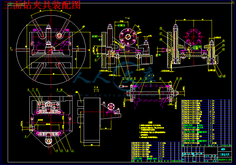
   铣刀头座体的夹具设计是这次课题的重要的部分,也是本次课题的难点分,夹具的设计主要是铣刀头的定位和夹紧。主要会影响加工元件的尺寸精度和位置精度。在本次课题中主要采用的是不完全定位方式,这种通用的定位方式的夹具的结构比较简单,并且有良好的定位的稳定性。夹紧机构主要采用螺旋式,这种结构的构成比较简单,自锁性能好,可靠性能高。在确定夹紧方式后绘出主要的零件图和装配图。


关键词:铣床;铣刀头座体;制造工艺;夹具设计


ABSTRACT

   Milling cutter head base is an integral component of milling manufacturing process and has a significant impact on the dimensional accuracy of milling . The purpose of this project is generally milling cutter head base mechanical manufacturing process and fixture design. In the first part of the manufacturing process design, the main work is casting of milling cutter head base , machining and line set, mechanical inspection and calculation process, the preparation of the main process documents.

   The Fixture Block of milling cutter head base is an important part of this project and also is a part of this difficult subject, mainly milling fixture design is clamping and positioning. these will affect the processing of the dimensional accuracy and position accuracy of main components. The issue is used three holes of the positioning in one surface . the positioning of such a general way the fixture structure is relatively simple and has good positioning stability. Clamping institutions are mainly spiral , the composition of this structure is relatively simple, self-locking performance, high reliability. drawing three-dimensional and assembly drawings.


Key words: milling machine; milling cutter head base; manufacturing processes;fixture design


目  录

摘要................................................................................................................................................III

ABSTRACT...................................................................................................................................IV

目录.................................................................................................................................................V

1 绪论.............................................................................................................................................1

 1.1 课题背景.............................................................................................................................1

   1.1.1铣刀头座体的概述.........................................................................................................1

   1.1.2铣刀头的现状和发展趋势.............................................................................................1

   1.1.3铣刀的分类.....................................................................................................................1

   1.1.4铣刀的结构和构成.........................................................................................................2

1.1.5夹具的现状及发展趋势.................................................................................................2

 1.2 本设计的内容及目的..........................................................................................................3

2 铣刀头座体的机械加工工艺规程设计.....................................................................................5

 2.1 铣刀头座体的工艺分析及生产类型确定..........................................................................5

   2.1.1 铣刀头座体的工艺分析...............................................................................................5

   2.1.2 铣刀头座体的生产类型...............................................................................................6

 2.2 确定毛坯的制造类型..........................................................................................................6

 2.3 基准的选择..........................................................................................................................6

   2.3.1 粗基准的选择...............................................................................................................6

   2.3.2 精基准的选择...............................................................................................................7

 2.4 零件表面加工方法的确定..................................................................................................7

 2.5 工艺路线的制定与分析......................................................................................................7

   2.5.1 工艺路线的拟定...........................................................................................................7

   2.5.2 工艺方案的分析与确定...............................................................................................8

 2.6 机械加工余量、毛坯工序尺寸的确定............................................................................10

2.6.1 孔的加工余量.............................................................................................................10

2.6.2 平面的加工余量.........................................................................................................10    

   2.6.3 切削用量及工时的计算.............................................................................................11

3 铣刀头座体专用夹具设计.......................................................................................................23

 3.1 夹具设计的原则和要求....................................................................................................23

   3.1.1 夹具设计的要求.........................................................................................................23

   3.1.2 六点定位原则.............................................................................................................23

 3.2  镗夹具的设计..................................................................................................................24

   3.2.1 确定定位方案.............................................................................................................24

   3.2.2 设计夹紧机构.............................................................................................................24


3.2.3 夹紧力的计算.............................................................................................................25

3.3.4 确定镗夹具总体结构和尺寸.....................................................................................25

3.3.5 使用说明.....................................................................................................................26

 3.3 钻孔夹具的设计................................................................................................................27

   3.3.1 定位基准的选择.........................................................................................................27

   3.3.2 切削力和夹紧力的计算.............................................................................................27

3.3.3 定位误差分析.............................................................................................................27

3.3.4 确定定位方案.............................................................................................................28

3.3.5 设计夹紧机构.............................................................................................................28

3.3.6 确定钻夹具总体结构和尺寸.....................................................................................28

3.3.7 使用说明.....................................................................................................................29

4 结论与展望...............................................................................................................................31

 4.1 结论....................................................................................................................................31

 4.2 不足之处与展望................................................................................................................31

致谢...............................................................................................................................................32

参考文献.......................................................................................................................................33


1 绪论

1.1 课题背景

 1.1.1 铣刀头座体的概述

   铣刀头座体是一种用于大件切削的机床附件,如装在龙门铣床上进行铣削加工。铣刀装在铣刀盘上,铣刀盘通过键与轴连接,当动力通过V 带传给带轮,经键传到轴,即可带动铣刀盘转动,对零件进行铣削加工。基础件座体,两端由圆锥滚子轴承支撑轴,轴承外测有轴承盖;左边带轮为动力输入端,带轮和轴由键连接,带轮的左侧有销、挡圈、螺钉实现定位和紧固。

内容简介:
编号 无锡 太湖学院 毕业设计(论文) 相 关 资 料 题目: 铣刀头座体零件工艺及工装设计 信机 系 机械 制造 及 自 动 化 专业 学 号: 0923063 学生姓名: 许 晓 峰 指导教师: 许 文 (职称: 副教授 ) (职称: ) 2013年 5月 25日 nts nts目 录 一、毕业设计(论文)开题报告 二、毕业设计(论文)外文资料翻译及原文 三、学生 “毕业论文(论文)计划、进度、检查及落实表 ” 四、实习鉴定表 nts nts无锡 太湖学院 毕业设计(论文) 开 题 报 告 题目: 铣刀头座体零件工艺及工装设计 信机 系 机械 工程 及自动化 专业 学 号: 0923063 学生姓名: 许 晓 峰 指导教师: 许 文 (职称: 副教授 ) (职称: ) 2012年 11月 25日 nts nts课题来源 本课题来自某机床厂的成熟产品,旨在培养学生解决工程实际问题的能力,达到学以致用的目的。 科学依据 (包括课题的科学意义;国内外研究概况、水平和发展趋势;应用前景等) ( 1)课题科学意义 铣刀头座体是铣床加工的重要组成元件之一,它的制造工艺对铣削加工的尺寸精度有显著的影响。 铣刀头座体是一种用于大件切削的机床附件,如装在龙门铣床上进行铣削加工。铣刀装在铣刀盘上,铣刀盘通过键与轴连接,当动力通过 V 带传给带轮,经键传到轴,即可带动铣刀盘转动,对零件进行铣削加工。基础件座体,两端由圆锥滚子轴承支撑轴,轴承外测有轴承盖;左边带轮为动力输入端,带轮和轴由键连接,带轮的左侧有销、挡圈、螺钉实现定位和紧固。 铣刀头现状和发展趋势 铣床是一种用途广泛的机床,在铣床上可以加工平面(水平面、垂直面)、沟槽(键槽、 T 形槽 、燕尾槽等)、分齿零件(齿轮、花键轴、链轮乖、螺旋形表面(螺纹、螺旋槽)及各种曲面。此外,还可用于对回转体表面、内孔加工及进行切断工作等。铣床在工作时,工件装在工作台上或分度头等附件上,铣刀旋转为主运动,辅以工作台或铣头的进给运动,工件即可获得所需的加工表面。由于是多刀断续切削,因而铣床的生产率较高。用铣刀对工件进行铣削加工的机床。铣床除能铣削平面、沟槽、轮齿、螺纹和花键轴外,还能加工比较复杂的型面, 效 率较刨床高,在机械制造和修理部门得到广泛应用。 ( 3)国内外研究概况 铣床最早是由美国人 E.惠特尼于 1818年创制的卧式铣床。为了铣削麻花钻头的螺旋槽,美国人 J.R.布朗于 1862年创制了第一台万能铣床,是为升降台铣床的雏形。 1884年前后出现了龙门铣床。 20世纪 20年代出现了半自动铣床,工作台利用挡块可完成“进给 -快速”或“快速 -进给”的自动转换。 1950年以后,铣床在控制系统方面发展很快,数字控制的应用大大提高了铣床的自动化程度。尤其是 70年代以后,微处理机的数字控制系统和自动换刀系统在铣床上得到应用,扩大了铣床的加工范围,提高了加工精度与效率。 nts研究内容 及目的 运用 AutoCAD 软件绘制铣刀头座 体 零件 的零件图 和毛坯 -零件图 ,根据图纸的技术要求等确定生产类型、切削加工方法、工艺路线的拟定 ; 进行工艺分析, 确定毛坯类型和制造方法 ; 对某道加工工序的夹具进行设计并绘制夹具装配图和主要零件图 ; 巩固我们大学里所学的知识,也是对所学知识色综合性的检验 ; 加强我们查阅资料的能力,熟悉有关资料;树立正确的设计思想,掌握设计方法,培养我们的实际工作能力; 通过对铣刀头座体的机械制造工艺设计,使我们在机械制造工艺规程设计,工艺 方案论证,机械加工余量计算,工艺尺寸的确定,编写技术文件及查 阅技术文献等各个方面都受到了一次综合性的训练 。 拟采取的研究方法、技术路线、实验方案及可行性分析 研究方法: 在导师的指导下进行,并且实地考察,观察工厂 铣床 的工作流程以及结构, 回头进行分析总结。 技术路线: 询问导师以及工厂车间等地的操作员具体对 铣床 的操作流程 。 实验方案: 就地考察,搜寻资料,导师提供,整理资料,完成实验。 可行性分析: 按照此流程分析,此次实验可以逐步完成。 nts研究计划及预期成果 研究计划: 2012 年 10 月 12 日 -2012 年 12 月 25 日:按照任务书要求查阅论文相关参考资料, 填写毕业设计开题报告书。 2013 年 1 月 11 日 -2013 年 3 月 5 日:填写毕业实习报告。 2013 年 3 月 8 日 -2013 年 3 月 14 日:按照要求修改毕业设计开题报告。 2013 年 3 月 15 日 -2013 年 3 月 21 日:学习并翻译一篇与毕业设计相关的英文材料。 2013 年 3 月 22 日 -2013 年 4 月 11 日: 抄画零件图 。 2013 年 4 月 12 日 -2013 年 4 月 25 日: 镗夹具以及钻夹具设计 。 2013 年 4 月 26 日 -2013 年 5 月 21 日:毕业论文撰写和修改工作。 预期成果: 1 对国内工程机械有更深刻的了解。 2 对钻 铣床 工 作 过 程要有掌握。 3 广泛了解工程机械的研发、制造和使用过程。 4 能够根据市场的需求,参与开发出相应的产品。 5 能够熟练使用各种工具书籍。 6 能够掌握典型零件的加工工艺。 特色或创新之处 设计出合理且简便的夹具; 设计出合理的工艺路线。 已具备的条件和尚需解决的问题 方案思路已经非常明确,已经具备 镗夹具以及钻夹具 的 相关 知识。 有关夹具的定位设计还有待改进 。 5 nts指导教师意见 指导教师签名: 年 月 日 教研室(学科组、研究所)意见 教研室主任签名: 年 月 日 系意见 主管领导签名: 年 月 日 nts英文原文 Numerical control technology and equipping development trend and countermeasure Equip the engineering level, level of determining the whole national economy of the modernized degree and modernized degree of industry, numerical control technology is it develop new developing new high-tech industry and most advanced industry to equip (such as information technology and his industry, biotechnology and his industry, aviation, spaceflight, etc. national defense industry) last technology and getting more basic most equipment. Marx has ever said the differences of different economic times, do not lie in what is produced, and lie in how to produce, produce with some means of labor . Manufacturing technology and equipping the most basic means of production that are that the mankind produced the activity, and numerical control technology is nowadays advanced manufacturing technology and equips the most central technology. Nowadays the manufacturing industry all around the world adopts numerical control technology extensively, in order to improve manufacturing capacity and level, improve the adaptive capacity and competitive power to the changeable market of the trends. In addition every industrially developed country in the world also classifies the technology and numerical control equipment of numerical control as the strategic materials of the country, not merely take the great measure to develop ones own numerical control technology and industry, and implement blockading and restrictive policy to our country in view of high-grade, precision and advanced key technology of numerical control and equipping. In a word, develop the advanced manufacturing technology taking numerical control technology as the core and already become every world developed country and accelerate economic development in a more cost-effective manner, important way to improve the overall national strength and national position. Numerical control technology is the technology controlled to mechanical movement and working course with digital information, integrated products of electromechanics that the numerical control equipment is the new technology represented by numerical control technology forms to the manufacture industry of the tradition and infiltration of the new developing manufacturing industry, namely the so-called digitization is equipped, its technological range covers a lot of fields: (1)Mechanical manufacturing technology; (2)Information processing, processing, transmission technology; (3)Automatic control technology; (4)Servo drive technology; (5)Technology of the sensor; (6)Software engineering ,etc. Development trend of a numerical control technology The application of numerical control technology has not only brought the revolutionary change to manufacturing industry of the tradition, make the manufacturing industry become the industrialized symbol , and with the constant development of numerical control technology and enlargement of the application, the development of some important trades (IT , automobile , light industry , medical treatment ,etc. ) to the national economy and the peoples livelihood of his plays a more and more important role, because the digitization that these trades needed to equip has already been the main trend of modern development. Numerical control technology in the world at present and equipping the development trend to see, there is the following several respect 1- in its main research focus. 1 A high-speed, high finish machining technology and new trend equipped The efficiency, quality are subjavanufacturing technology. High-speed, high finish machining ntstechnology can raise the efficiency greatly , improve the quality and grade of the products, shorten production cycle and improve the market competitive power. Japan carries the technological research association first to classify it as one of the 5 great modern manufacturing technologies for this, learn (CIRP) to confirm it as the centre in the 21st century and study one of the directions in international production engineering. In the field of car industry, produce one second when beat such as production of 300,000 / vehicle per year, and many variety process it is car that equip key problem that must be solved one of; In the fields of aviation and aerospace industry, spare parts of its processing are mostly the thin wall and thin muscle, rigidity is very bad, the material is aluminium or aluminium alloy, only in a situation that cut the speed and cut strength very small high, could process these muscles, walls. Adopt large-scale whole aluminium alloy method that blank pay empty make the wing recently, such large-scale parts as the fuselage ,etc. come to substitute a lot of parts to assemble through numerous rivet , screw and other connection way, make the intensity , rigidity and dependability of the component improved. All these, to processing and equipping the demand which has proposed high-speed, high precise and high flexibility. According to EMO2001 exhibition situation, high-speed machining center is it give speed can reach 80m/min is even high , air transport competent speed can up to 100m/min to be about to enter. A lot of automobile factories in the world at present, including Shanghai General Motors Corporation of our country, have already adopted and substituted and made the lathe up with the production line part that the high-speed machining center makes up. HyperMach lathe of U.S.A. CINCINNATI Company enters to nearly biggest 60m/min of speed, it is 100m/min to be fast, the acceleration reaches 2g, the rotational speed of the main shaft has already reached 60 000r/min. Processing a thin wall of plane parts, spend 30min only, and same part general at a high speed milling machine process and take 3h, the ordinary milling machine is being processed to need 8h; The speed and acceleration of main shaft of dual main shaft lathes of Germany DMG Company are up to 120000r/mm and 1g. In machining accuracy, the past 10 years, ordinary progression accuse of machining accuracy of lathe bring 5m up to from 10m already, accurate grades of machining center from 3 5m, rise to 1 1.5m, and ultraprecision machining accuracy is it enter nanometer grade to begin already (0.01m). In dependability, MTBF value of the foreign numerical control device has already reached above 6 000h, MTBF value of the servo system reaches above 30000h, demonstrate very high dependability . In order to realize high-speed, high finish machining, if the part of function related to it is electric main shaft, straight line electrical machinery get fast development, the application is expanded further . 1.2 Link and process and compound to process the fast development of the lathe in 5 axes Adopt 5 axles to link the processing of the three-dimensional curved surface part, can cut with the best geometry form of the cutter , not only highly polished, but also efficiency improves by a large margin . It is generally acknowledged, the efficiency of an 5 axle gear beds can equal 2 3 axle gear beds, is it wait for to use the cubic nitrogen boron the milling cutter of ultra hard material is milled and pared at a high speed while quenching the hard steel part, 5 axles link and process 3 constant axles to link and process and give play to higher benefit. Because such reasons as complicated that 5 axles link the numerical control system , host computer structure that but go over, it is several times higher that its price links the numerical control lathe than 3 axles , in addition the technological degree of difficulty of programming is relatively great, have restricted the development of 5 axle gear beds. At present because of electric appearance of main shaft, is it realize 5 axle complex main shaft hair structure processed to link greatly simplify to make, it makes degree of difficulty and ntsreducing by a large margin of the cost, the price disparity of the numerical control system shrinks. So promoted 5 axle gear beds of head of complex main shaft and compound to process the development of the lathe (process the lathe including 5). At EMO2001 exhibition, new Japanese 5 of worker machine process lathe adopt complex main shaft hair, can realize the processing of 4 vertical planes and processing of the wanton angle, make 5 times process and 5 axles are processed and can be realized on the same lathe, can also realize the inclined plane and pour the processing of the hole of awls. Germany DMG Company exhibits the DMUVoution series machining center, but put and insert and put processing and 5 axles 5 times to link and process in once, can be controlled by CNC system or CAD/CAM is controlled directly or indirectly. 1.3 Become the main trend of systematic development of contemporary numerical control intelligently, openly, networkedly. The numerical control equipment in the 21st century will be sure the intelligent system, the intelligent content includes all respects in the numerical control system: It is intelligent in order to pursue the efficiency of processing and process quality, control such as the self-adaptation of the processing course, the craft parameter is produced automatically; Join the convenient one in order to improve the performance of urging and use intelligently, if feedforward control , adaptive operation , electrical machinery of parameter , discern load select models , since exactly makes etc. automatically; The ones that simplified programming , simplified operating aspect are intelligent, for instance intelligent automatic programming , intelligent man-machine interface ,etc.; There are content of intelligence diagnose , intelligent monitoring , diagnosis convenient to be systematic and maintaining ,etc. Produce the existing problem for the industrialization of solving the traditional numerical control system sealing and numerical control application software. A lot of countries carry on research to the open numerical control system at present, such as NGC of U.S.A. (The Next Generation Work-Station/Machine Control), OSACA of European Community (Open System Architecture for Control within Automation Systems), OSEC (Open System Environment for Controller) of Japan, ONC (Open Numerical Control System) of China, etc. The numerical control system melts to become the future way of the numerical control system open. The so-called open numerical control system is the development of the numerical control system can be on unified operation platform, face the lathe producer and end user, through changing, increasing or cutting out the structure target(numerical control function), form the serration, and can use users specially conveniently and the technical know-how is integrated in the control system, realize the open numerical control system of different variety , different grade fast, form leading brand products with distinct distinction. System structure norm of the open numerical control system at present, communication norm , disposing norm , operation platform , numerical control systematic function storehouse and numerical control systematic function software development ,etc. are the core of present research. The networked numerical control equipment is a new light spot of the fair of the internationally famous lathe in the past two years. Meeting production line , manufacture system , demand for the information integration of manufacturing company networkedly greatly of numerical control equipment, realize new manufacture mode such as quick make , fictitious enterprise , basic Entrance that the whole world make too. Some domestic and international famous numerical control lathes and systematic manufacturing companies of numerical control have all introduced relevant new concepts and protons of a machine in the past two years, if in EMO2001 exhibition, Cyber Production Center that the company exhibits of mountain rugged campstool gram in Japan (Mazak) (intellectual central production control unit, abbreviated as CPC); The lathe company of Japanese big Wei (Okuma ) exhibits IT plaza (the information technology square , is ntsabbreviated as IT square ); Open Manufacturing Environment that the company exhibits of German Siemens (Siemens ) (open the manufacturing environment, abbreviated as OME),etc., have reflected numerical control machine tooling to the development trend of networked direction. 1.4 Pay attention to the new technical standard, normal setting-up 1.4.1 Design the norm of developing about the numerical control system As noted previously, there are better common ability, flexibility, adaptability, expanding in the open numerical control system, such countries as U.S.A. ,European Community and Japan ,etc. implement the strategic development plan one after another , carry on the research and formulation of the systematic norm (OMAC , OSACA , OSEC ) of numerical control of the open system structure, 3 biggest economies in the world have carried on the formulation that nearly the same science planned and standardized in a short time, have indicated a new arrival of period of change of numerical control technology. Our country started the research and formulation of standardizing the frame of ONC numerical control system of China too in 2000. 1.4.2 About the numerical control standard The numerical control standard is a kind of trend of information-based development of manufacturing industry. Information exchange among 50 years after numerical control technology was born was all because of ISO6983 standard, namely adopt G, M code describes how processes, its essential characteristic faces the processing course, obviously, he cant meet high-speed development of modern numerical control technologys needs more and more already. For this reason, studying and making a kind of new CNC system standard ISO14649 (STEP-NC) in the world, its purpose is to offer a kind of neutral mechanism not depending on the concrete system, can describe the unified data model in cycle of whole life of the products, thus realize the whole manufacture process, standardization of and even each industrial field product information. The appearance of STEP-NC may be a revolution of the technological field of the numerical control, on the development and even the whole manufacturing industry of numerical control technology, will exert a far-reaching influence. First of all, STEP-NC puts forward a kind of brand-new manufacture idea, in the traditional manufacture idea, NC processes the procedures to all concentrate on individual computer. Under the new standard, NC procedure can be dispersed on Internet, this is exactly a direction of open , networked development of numerical control technology. Secondly, STEP-NC numerical control system can also reduce and process the drawing (about 75%), process the procedure to work out the time (about 35%) and process the time (about 50%) greatly. At present, American-European countries pay much attention to the research of STEP-NC, Europe initiates IMS plan (1999.1.1-2001.12.3) of STEP-NC. 20 CAD/CAM/CAPP/CNC users, manufacturers and academic organizations from Europe and Japan participated in this plan. STEP Tools Company of U.S.A. is a developer of the data interchange software of manufacturing industry in the global range, he has already develo
温馨提示:
1: 本站所有资源如无特殊说明,都需要本地电脑安装OFFICE2007和PDF阅读器。图纸软件为CAD,CAXA,PROE,UG,SolidWorks等.压缩文件请下载最新的WinRAR软件解压。
2: 本站的文档不包含任何第三方提供的附件图纸等,如果需要附件,请联系上传者。文件的所有权益归上传用户所有。
3.本站RAR压缩包中若带图纸,网页内容里面会有图纸预览,若没有图纸预览就没有图纸。
4. 未经权益所有人同意不得将文件中的内容挪作商业或盈利用途。
5. 人人文库网仅提供信息存储空间,仅对用户上传内容的表现方式做保护处理,对用户上传分享的文档内容本身不做任何修改或编辑,并不能对任何下载内容负责。
6. 下载文件中如有侵权或不适当内容,请与我们联系,我们立即纠正。
7. 本站不保证下载资源的准确性、安全性和完整性, 同时也不承担用户因使用这些下载资源对自己和他人造成任何形式的伤害或损失。
提示  人人文库网所有资源均是用户自行上传分享,仅供网友学习交流,未经上传用户书面授权,请勿作他用。
关于本文
本文标题:铣刀头尾座体零件工艺及工装夹具设计[2副]【24张CAD图纸+毕业论文】【答辩通过】
链接地址:https://www.renrendoc.com/p-445798.html

官方联系方式

2:不支持迅雷下载,请使用浏览器下载   
3:不支持QQ浏览器下载,请用其他浏览器   
4:下载后的文档和图纸-无水印   
5:文档经过压缩,下载后原文更清晰   
关于我们 - 网站声明 - 网站地图 - 资源地图 - 友情链接 - 网站客服 - 联系我们

网站客服QQ:2881952447     

copyright@ 2020-2025  renrendoc.com 人人文库版权所有   联系电话:400-852-1180

备案号:蜀ICP备2022000484号-2       经营许可证: 川B2-20220663       公网安备川公网安备: 51019002004831号

本站为文档C2C交易模式,即用户上传的文档直接被用户下载,本站只是中间服务平台,本站所有文档下载所得的收益归上传人(含作者)所有。人人文库网仅提供信息存储空间,仅对用户上传内容的表现方式做保护处理,对上载内容本身不做任何修改或编辑。若文档所含内容侵犯了您的版权或隐私,请立即通知人人文库网,我们立即给予删除!