翻译原稿.pdf

香烟横包机右支架工艺规程及夹具设计【14张CAD图纸+毕业论文】【答辩通过】

收藏

资源目录
跳过导航链接。
香烟横包机右支架工艺规程及夹具设计【全套CAD图纸+毕业论文】【答辩通过】.rar
香烟横包机右支架工艺规程及夹具设计
翻译原稿.pdf---(点击预览)
翻译.doc---(点击预览)
毕业设计说明书.doc---(点击预览)
摘 要.doc---(点击预览)
开题报告.doc---(点击预览)
工艺过程卡.doc---(点击预览)
任务书-2010.doc---(点击预览)
工序卡
10.dwg04.dwg
11.dwg04.dwg
12.dwg04.dwg
14.dwg04.dwg
15.dwg04.dwg
16.dwg04.dwg
17.dwg04.dwg
18.dwg04.dwg
19.dwg04.dwg
20.dwg04.dwg
21.dwg04.dwg
22.dwg04.dwg
23.dwg04.dwg
24.dwg04.dwg
25.dwg04.dwg
26.dwg04.dwg
3.dwg04.dwg
4.dwg04.dwg
5.dwg04.dwg
6.dwg04.dwg
7.dwg04.dwg
8.dwg04.dwg
9.dwg09.dwg
压板螺栓.dwg04.dwg
支撑板零件图A3-8.dwg04.dwg
球面浮动杠杆A3-7.dwg04.dwg
球面螺杆.dwg04.dwg
装配图A0-1.dwg04.dwg
起吊螺钉.dwg04.dwg
转动压板1A3-6.dwg04.dwg
转动压板2.dwg04.dwg
镗套A.dwg04.dwg
镗套B.dwg04.dwg
镗套C.dwg04.dwg
镗模支架A2-4.dwg04.dwg
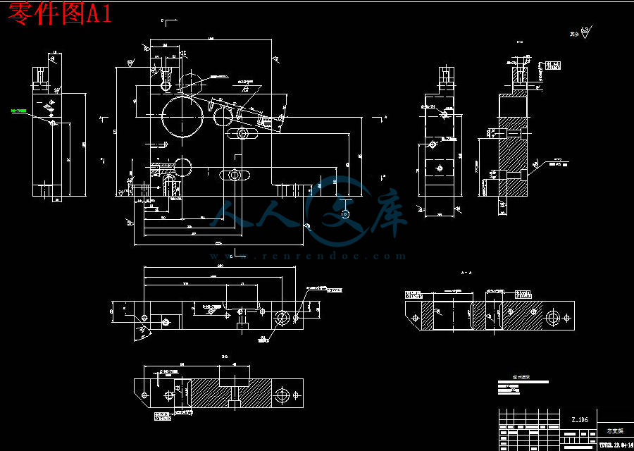
零件图A1-3.dwg04.dwg
零件毛坯图A2-5.dwg04.dwg
压缩包内文档预览:
预览图 预览图 预览图 预览图 预览图 预览图 预览图 预览图 预览图 预览图 预览图 预览图 预览图 预览图 预览图 预览图
编号:445812    类型:共享资源    大小:1.78MB    格式:RAR    上传时间:2015-07-02 上传人:好资料QQ****51605 IP属地:江苏
45
积分
关 键 词:
香烟 包机 支架 工艺 规程 夹具 设计 全套 cad 图纸 毕业论文 答辩 通过
资源描述:

香烟横包机右支架工艺规程及夹具设计


摘要:本课题是香烟横包机右支架的机械加工工艺设计和镗床镗模设计,因为零件本身不是很复杂,而且加工精度不是很高,所以其工艺简单。通过对零件的工艺分析,设计了工艺规程,确定了其毛坯的制造形式、加工基准和设计基准、工艺路线、机械加工余量和各工序的切削用量及基本工时,也确定了选用的刀具与机床。为提高劳动生产效率,降低劳动强度,设计了三个平行孔的专用夹具,基于零件的几何形状,设计其夹具为T68镗床上的专用镗模,通过对其定位基准、引刀方式、夹紧方案的选择,最终确定了主要用于加工零件的孔系的镗模,它依靠专用的导向元件——镗套引导镗孔刀具,保证了加工达到了较高的位置精度,并使镗孔的位置精度不受机床精度的影响,利用其夹具精加工孔系时保证了平行孔轴线距误差小于±0.02mm;平行孔的不平行或不垂直度小于0.01/200;平行孔不同轴度误差小于0.01mm。


关键词:加工工艺,夹具,加工精度,镗模


The right support cigarettes horizontal packaging machine’s Technology of order and Fixture design


Abstract:The issue is the right of cigarettes Wang charter stent machining process design and boring - boring machine design, because parts itself is not very complicated and machining accuracy is not very high, so its simple process. Part of the process analysis, design of process in order and set its rough form the manufacture, processing benchmarks and design criteria, process line, machinery allowance and the amount of the cutting process and the basic hours of work, defines the use of knives and machine tools. To improve labor productivity and reduce labor intensity, the three parallel design Kong special fixture, Based on the geometry of components, fixture design for its T68 Boring Boring on the dedicated mode, through its positioning benchmarks primers knife, the choice of clamping program, and the final of the main components for the processing of boring holes mold, It relies on a dedicated oriented components -- guide sets Boring Boring Tool ensure that the processing to achieve a higher position accuracy, Boring enable the location accuracy from the impact of precision machine tools, use their fixture finishing holes at ensuring the parallel hole axis from the error is less than ± 0.02 mm; The parallel hole parallel or vertical  is less than 0.01/200; Hole different parallel axis error of less than 0.01 mm.

Keywords:Processing ,Fixture,Precision Machining,Boring die,

目录

1  绪论2

1.1 现代制造技术和工艺2

1.2现代机械工业的生产特点2

1.3夹具及其作用3

1.4现代机床夹具的发展方向3

1.5 本课题的任务和主要内容5

2 零件的分析6

2.1零件的结构与作用6

3 工艺规程的设计9

3.1确定毛坯的制造形式9

3.2 基准的选择9

3.3 制订工艺路线9

3.4 机械加工余量10

3.5 确定切削用量及基本工时14

4 专用夹具设计31

4.1 问题提出31

4.2 夹具的设计31

结论36

致谢37

参考文献38


绪论

1.1 现代制造技术和工艺

现代制造技术包括材料、工艺、设计、制造、管理等方面的新兴技术,现代制造技术的应用是中国制造业发展的脊梁,机械制造业是国民经济最重要的基础产业,而机械制造技术的不断创新则是机械工业发展的技术基础和动力。现代制造技术是以传统制造技术与计算机技术、信息技术、自动控制技术等现代高新技术交叉融合的结果,是一个集机械、电子、信息、材料与管理技术于一体的新型交叉学科,它使制造技术的技术内涵和水平发生了质的变化。因此,凡是那些能够融合当代科学进步的最新成果,最能发挥人和设备的潜力,最能体现现代制造水平的制造技术均称为现代制造技术,它给传统的机械制造业带来了勃勃生机。现代机械制造技术的发展主要表现在两个方向上:一是精密工程技术,以超精密加工的前沿部分、微细加工、纳米技术为代表,将进入微型机械电子技术和微型机器人的时代;二是机械制造的高度自动化,以CIMS和敏捷制造等的进一步发展为代表。

机械制造工艺是各种机械的制造方法和过程的总称。其研究对象是机械产品的制造工艺,包括零件加工和装配两方面。工艺是使各种原材料、半成品成为产品的方法和过程,是生产中最活跃的因素,落实在由工件、刀具、机床、夹具所构成的工艺系统中,和生产实际联系十分紧密。

内容简介:
International Journal of Machine Tools & Manufacture 42 (2002) 505520Five-axis milling machine tool kinematic chain design and analysisE.L.J. Bohez*Department of Design and Manufacturing Engineering, Asian Institute of Technology, P.O. Box 4, Klong Luang, 12120 Pathumthani, ThailandReceived 23 May 2000; received in revised form 12 September 2001; accepted 13 September 2001AbstractFive-axis CNC machining centers have become quite common today. The kinematics of most of the machines are based on arectangular Cartesian coordinate system. This paper classifies the possible conceptual designs and actual existing implementationsbased on the theoretically possible combinations of the degrees of freedom. Some useful quantitative parameters, such as theworkspace utilization factor, machine tool space efficiency, orientation space index and orientation angle index are defined. Theadvantages and disadvantages of each concept are analyzed. Criteria for selection and design of a machine configuration are given.New concepts based on the Stewart platform have been introduced recently in industry and are also briefly discussed. 2002Elsevier Science Ltd. All rights reserved.Keywords: Five-axis; Machine tool; Kinematic chain; Workspace; CNC; Rotary axis1. IntroductionThe main design specifications of a machine tool canbe deduced from the following principles:L50539 The kinematics should provide sufficient flexibility inorientation and position of tool and part.L50539 Orientation and positioning with the highest poss-ible speed.L50539 Orientation and positioning with the highest poss-ible accuracy.L50539 Fast change of tool and workpiece.L50539 Save for the environment.L50539 Highest possible material removal rate.The number of axes of a machine tool normally refersto the number of degrees of freedom or the number ofindependent controllable motions on the machine slides.The ISO axes nomenclature recommends the use of aright-handed coordinate system, with the tool axis corre-sponding to the Z-axis. A three-axis milling machine hasthree linear slides X, Y and Z which can be positionedeverywhere within the travel limit of each slide. The toolaxis direction stays fixed during machining. This limits* Tel.: +66-2-524-5687; fax: +66-2-524-5697.E-mail address: bohezait.ac.th (E.L.J. Bohez).0890-6955/02/$ - see front matter 2002 Elsevier Science Ltd. All rights reserved.PII: S0890-6955(01)00134-1the flexibility of the tool orientation relative to the work-piece and results in a number of different set ups. Toincrease the flexibility in possible tool workpiece orien-tations, without need of re-setup, more degrees of free-dom must be added. For a conventional three linear axesmachine this can be achieved by providing rotationalslides. Fig. 1 gives an example of a five-axis millingmachine.Fig. 1. Five-axis machine tool.nts506 E.L.J. Bohez / International Journal of Machine Tools & Manufacture 42 (2002) 5055202. Kinematic chain diagramTo analyze the machine it is very useful to make akinematic diagram of the machine. From this kinematic(chain) diagram two groups of axes can immediately bedistinguished: the workpiece carrying axes and the toolcarrying axes. Fig. 2 gives the kinematic diagram of thefive-axis machine in Fig. 1. As can be seen the work-piece is carried by four axes and the tool only by oneaxis.The five-axis machine is similar to two cooperatingrobots, one robot carrying the workpiece and one robotcarrying the tool.Five degrees of freedom are the minimum required toobtain maximum flexibility in tool workpiece orien-tation, this means that the tool and workpiece can beoriented relative to each other under any angle. Theminimum required number of axes can also be under-stood from a rigid body kinematics point of view. Toorient two rigid bodies in space relative to each other 6degrees of freedom are needed for each body (tool andworkpiece) or 12 degrees. However any common trans-lation and rotation which does not change the relativeorientation is permitted reducing the number of degreesby 6. The distance between the bodies is prescribed bythe toolpath and allows elimination of an additionaldegree of freedom, resulting in a minimum requirementof 5 degrees.3. Literature reviewOne of the earliest (1970) and still very useful intro-ductions to five-axis milling was given by Baughman 1clearly stating the applications. The APT language wasthen the only tool to program five-axis contouring appli-cations. The problems in postprocessing were alsoFig. 2. Kinematic chain diagram.clearly stated by Sim 2 in those earlier days of numeri-cal control and most issues are still valid. Boyd in Ref.3 was also one of the early introductions. Beziers book4 is also still a very useful introduction. Held 5 givesa very brief but enlightening definition of multi-axismachining in his book on pocket milling. A recent paperapplicable to the problem of five-axis machine work-space computation is the multiple sweeping using theDenawit-Hartenberg representation method developedby Abdel-Malek and Othman 6.Many types and design concepts of machine toolswhich can be applied to five-axis machines are discussedin Ref. 7 but not specifically for the five-axis machine.The number of setups and the optimal orientation ofthe part on the machine table is discussed in Ref. 8. Areview about the state of the art and new requirementsfor tool path generation is given by B.K. Choi et al. 9.Graphic simulation of the interaction of the tool andworkpiece is also a very active area of research and agood introduction can be found in Ref. 10.4. Classification of five-axis machines kinematicstructureStarting from Rotary (R) and Translatory (T) axes fourmain groups can be distinguished: (i) three T axes andtwo R axes; (ii) two T axes and three R axes; (iii) oneT axis and four R axes and (iv) five R axes. Nearly allexisting five-axis machine tools are in group (i). Also anumber of welding robots, filament winding machinesand laser machining centers fall in this group. Only lim-ited instances of five-axis machine tools in group (ii)exist for the machining of ship propellers. Groups (iii)and (iv) are used in the design of robots usually withmore degrees of freedom added.The five axes can be distributed between the work-piece or tool in several combinations. A first classi-fication can be made based on the number of workpieceand tool carrying axes and the sequence of each axis inthe kinematic chain. Another classification can be basedon where the rotary axes are located, on the workpieceside or tool side. The five degrees of freedom in a Car-tesian coordinates based machine are: three translatorymovements X,Y,Z (in general represented as TTT) andtwo rotational movements AB, AC or BC (in general rep-resented as RR).Combinations of three rotary axes (RRR)and two linear axes (TT) are rare. If an axis is bearingthe workpiece it is the habit of noting it with anadditional accent. The five-axis machine in Fig. 1 canbe characterized by XH11032YH11032AH11032BH11032Z. The XYAB axes carry theworkpiece and the Z-axis carries the tool. Fig. 3 showsa machine of the type XYZAH11032BH11032, the three linear axescarry the tool and the two rotary axes carry the work-piece.nts507E.L.J. Bohez / International Journal of Machine Tools & Manufacture 42 (2002) 505520Fig. 3. XYZAH11032BH11032 machinery.4.1. Classification based on the sequence of workpieceand tool carrying axesTheoretically the number of possible configurations isquite large if the order of the axes in the two kinematicchains of the tool and workpiece carrying axes is countedas a different configuration. Also the combinations withonly two linear axes and three rotary axes are included.One tool carrying axis and four workpiece carryingaxes can be combined in a five-axis machine as follows:for each possible tool carrying axis X,Y,Z,A,B,C the otherfour workpiece carrying axes can be selected from thefive remaining axes. So the number of combinations offour axes out of five with considering different permu-tation as another configuration is 54!=120 for eachpossible tool axis selection (1 out of 6 or 6 possibilities).So theoretically there are 6120=720 possible five-axismachines with one tool carrying axis. The same analysiscan be done for all other combinations. With t the num-ber of tool carrying axes and w the number of workpiececarrying axes (w+t=5) the total number of combinationsis as follows.Ncomb=H208736tH20874t!H208736twH20874w! tH113493, t+w=5 (1)Ncomb=H208736wH20874w!H208736wtH20874t! tH110223, t+w=5 (2)The value of this equation is always equal to 6! or720 when w+t=5. Some of these 720 combinations willbe containing only two linear axis. If only five-axismachines with three linear axes are considered, only35!=360 combinations are still possible.The set Gt of combinations is characterized by a fixedvalue of t. This set is identical to the set GH11032w charac-terized by a fixed value of w, w=5H11002t. Using above defi-nitions following subgroups of five-axis machines exist:(i) Group G0/GH110325; (ii) Group G1/GH110324; (iii) GroupG2/GH110323; (iv) Group G3/GH110322; (v) Group G4/GH110321; (vi)Group G5/GH1103. G5/G0H11032 machineAll axes carry the tool and the workpiece is fixed ona fixed table. Fig. 4 shows a machine with all the fiveaxes carrying the tool. The kinematic chain is XBYAZ(TRTRT). This machine was one of the earliest modelsof five-axis machines to handle very heavy workpieces.As there are many links in the tool carrying kinematicchain, there can be a considerable error due to elasticdeformations and backlash in the slides.4.1.2. G0/G5H11032 machineAll axes carry the workpiece and the tool is fixed inspace. This construction is best used for very smallworkpieces (see Section 6.3).Fig. 4. XBYAZ machine.nts508 E.L.J. Bohez / International Journal of Machine Tools & Manufacture 42 (2002) 5055204.1.3. G4/G1H11032 machineFour axes carry the tool and one axis carries the work-piece. There are basically two possibilities, the work-piece carrying axis can be RH11032 or TH110. G1/G4H11032 machineOne axis carries the tool and the other four axes carrythe workpiece. There are basically two possibilities, thesingle axis kinematic chain can be R or T. Fig. 1 is anexample of such a machine, with the single tool carryingaxis T.4.1.5. G3/G2H11032 machineThree axes carry the tool and two axes carry the work-piece. There are basically three possibilities, the work-piece carrying axes can be both linear (TH11032TH11032) bothrotational (RH11032RH11032) or mixed (TH11032RH11032). Fig. 5 gives anexample of a machine with the tool carried by two rotaryaxes and one linear axis. This machine allows processingof large workpieces but the construction of the toolsideis complicated. The most common configuration is theworkpiece carried by the two rotary axes such as the onegiven in Figs. 3, 6 and . G2/G3H11032 machineTwo axes carry the tool and three axes carry the work-piece. There are basically three possibilities, the tool car-rying axis can be both linear (TT) both rotational (RR)or mixed (TR). Fig. 7 shows the mixed construction. Fig.8 shows two linear axes carrying the tool.4.2. Classification based on the location of rotaryaxesThe machines can be classified depending on the placewhere the rotation axes are implemented.Fig. 5. XH11032ZH11032CAY machine.Fig. 6. BH11032CH11032ZYX machine.Fig. 7. ZH11032XH11032CH11032BY machine.nts509E.L.J. Bohez / International Journal of Machine Tools & Manufacture 42 (2002) 505520Fig. 8. ZH11032AH11032BH11032YX machine.Only machines with two rotary axes and three linearaxes will be considered further. The possible configur-ations are:(a) rotation axes are implemented on tool spindle;(b) rotation axes are implemented on machine table;(c) combination of both.The sequence of the axes in the tool or workpiececarrying kinematic chain is not important if the axes areof the same type R or T. In general, if there are NH11032Ttrans-latory axes and NH11032Rrotary axes in the workpiece carryingkinematic chain and NTtranslatory axes and NRrotaryaxes in the tool kinematic chain, then the numbers ofcombinations is 11:NcombH11005(NH11032TH11001NH11032R)!NH11032T!NH11032R!(NTH11001NR)!NT!NR(3)with NH11032TH11001NTH110053, NH11032RH11001NRH110052The number of combinations of each group will be givenbelow case by case. The total number of combinationsover all groups is 60. From the design point of view thisis a more tractable number of alternatives to be con-sidered.4.2.1. RH11032RH11032 machineThe two rotary axes carry the workpiece. The tool axiscan be fixed or carried by one (T), two (TT) or three(TTT) linear axes.The number of possible designs is the sum of the fol-lowing combinations:(i) For the group G0/G5H11032 the tool is fixed in space allthe five axes will carry the workpiece. The numberof different designs is 10 (NTH11032=3 and NRH11032 =2), (Figs.15 and 16).(ii) For the group G1/G4H11032, NT+NR=1, so NT=1 and NR=0,is the only possible choice for the tool kinematicchain. Equation (3) gives NCOMB=6. The combi-nations are: RH11032RH11032TH11032TH11032T; TH11032TH11032RH11032RH11032T; RH11032TH11032RH11032TH11032T;TH11032RH11032TH11032RH11032T; RH11032TH11032TH11032RH11032T; TH11032RH11032RH11032TH11032T. Fig. 9 showsthese six designs.(iii) For the group G2/G3H11032 the tool axes are TT so NTH11032=1,NRH11032=2, NT=2, NR=0 and Equation (2) gives NCOMB=3.The three design combinations are: RH11032RH11032TH11032TT;RH11032TH11032RH11032TT and TH11032RH11032RH11032TT. The group G2/G3H11032 containsthree instances of the RH11032RH11032 machine. These instancesare represented in Fig. 10.(vi) If the tool axes are TTT the workpiece carrying axescan only be RH11032RH11032. So only one design combinationis possible.From the above-mentioned findings it can also be con-cluded that the total number of RH11032RH11032 five-axis machineconfigurations is 20.Machines with two axes on the clamping table can beseen in Figs. 1, 3, 6 and 8. The advantages are:Fig. 9. Members of group G1/G4H11032.nts510 E.L.J. Bohez / International Journal of Machine Tools & Manufacture 42 (2002) 505520Fig. 10. RH11032RH11032 machines in group G2/G3H11032.L50539 In case the spindle is horizontal, optimal chip removalis obtained through the gravitational effect of thechips just dropping.L50539 The tool axis during machining is always parallel tothe Z axis of the machine. So the drilling cycles canbe executed along the Z-axis of the machine. Circlesunder a certain orientation of the workpiece arealways executed in the XY plane of the machine. Theabove-mentioned functions can be executed in thesimple three-axis numerical control mode.L50539 The compensation of the tool length happens all thetime in the NC control of the machine, as with three-axis machines.Disadvantages:L50539 Machines with a rotating table are only for work-pieces with limited dimensions.L50539 The useful workspace is usually much smaller thanthe product of the travel in X,Y and Z axis.L50539 The transformation of the Cartesian CAD/CAM coor-dinate (XYZIJK) of the tool position to the machineaxes positions (XYZAB or C) is dependent on the pos-ition of the workpiece on the machine table. Thismeans that in case the position of the workpiece onthe table is changed this cannot be modified by atranslation of the axes system in the NC program.They must be recalculated. In case the control of theNC machine cannot transform Cartesian coordinatesto machine coordinates, then a new CNC programmust be generated with the postprocessor of theCAD/CAM system every time the position of theworkpiece changes.Important applications for this type:L50539 Five-sided cutting of electrodes for EDM and otherworkpiece.L50539 Machining of precision workpieces.L50539 Turbines and tire profiles with a certain workpiecegeometry rotated over a certain angle. The same NCprogram can be repeated after the zero of the rotationaxis has been inclined over a certain angle.4.2.2. RR-machineThe number of possible design combinations(NCOMP=20) is the same as in the case of the RH11032RH11032machine because of the symmetry. Five-axis machineswith the rotation axes implemented on the tool axisspindle can be seen in Figs. 4 and 5.Advantages:L50539 These machines can machine very large workpieces.L50539 The machine axis values of the NC program XYZ,depend on the tool length only. A new clamping pos-ition of the workpiece is corrected with a simpletranslation. This happens with a zero translation in theCNC control of the machine.Disadvantages:L50539 The drive of the main spindle is very complex. Simpledesign and construction is only obtained when thewhole spindle with the motor itself is rotating.L50539 There is a lower stiffness because the rotation axis ofthe spindle is limiting the force transmission. At highrevolutions per minute (higher than 5000 rpm) thereis also a counter acting moment because of the gyro-scopic effect which could be a disadvantage in casethe tool spindle is turning very fast.L50539 Circular interpolation in a random plane and drillingcycles under random orientation are often notimplemented.L50539 A change in the tool length cannot be adjusted by azero translation in the control unit, often a completerecalculation of the program (or postprocessing) isrequired.Important applications of this type of machine tool are:L50539 All types of very large workpieces such as air planewings.4.2.3. RH11032R machineOne rotary axis is implemented in the workpiece kine-matic chain and the other rotary axes in the tool kinem-atic chain (e.g. Fig. 7).The groups G4/G1H11032, G4H11032/G1, G3H11032/G2, G3/G2H11032 coverthis design. Nowadays there are many machines on themarket with one rotation axis on the tool spindle andnts511E.L.J. Bohez / International Journal of Machine Tools & Manufacture 42 (2002) 505520one rotation axis on the table. They are, however, com-bining most of the disadvantages of both previous type
温馨提示:
1: 本站所有资源如无特殊说明,都需要本地电脑安装OFFICE2007和PDF阅读器。图纸软件为CAD,CAXA,PROE,UG,SolidWorks等.压缩文件请下载最新的WinRAR软件解压。
2: 本站的文档不包含任何第三方提供的附件图纸等,如果需要附件,请联系上传者。文件的所有权益归上传用户所有。
3.本站RAR压缩包中若带图纸,网页内容里面会有图纸预览,若没有图纸预览就没有图纸。
4. 未经权益所有人同意不得将文件中的内容挪作商业或盈利用途。
5. 人人文库网仅提供信息存储空间,仅对用户上传内容的表现方式做保护处理,对用户上传分享的文档内容本身不做任何修改或编辑,并不能对任何下载内容负责。
6. 下载文件中如有侵权或不适当内容,请与我们联系,我们立即纠正。
7. 本站不保证下载资源的准确性、安全性和完整性, 同时也不承担用户因使用这些下载资源对自己和他人造成任何形式的伤害或损失。
提示  人人文库网所有资源均是用户自行上传分享,仅供网友学习交流,未经上传用户书面授权,请勿作他用。
关于本文
本文标题:香烟横包机右支架工艺规程及夹具设计【14张CAD图纸+毕业论文】【答辩通过】
链接地址:https://www.renrendoc.com/p-445812.html

官方联系方式

2:不支持迅雷下载,请使用浏览器下载   
3:不支持QQ浏览器下载,请用其他浏览器   
4:下载后的文档和图纸-无水印   
5:文档经过压缩,下载后原文更清晰   
关于我们 - 网站声明 - 网站地图 - 资源地图 - 友情链接 - 网站客服 - 联系我们

网站客服QQ:2881952447     

copyright@ 2020-2025  renrendoc.com 人人文库版权所有   联系电话:400-852-1180

备案号:蜀ICP备2022000484号-2       经营许可证: 川B2-20220663       公网安备川公网安备: 51019002004831号

本站为文档C2C交易模式,即用户上传的文档直接被用户下载,本站只是中间服务平台,本站所有文档下载所得的收益归上传人(含作者)所有。人人文库网仅提供信息存储空间,仅对用户上传内容的表现方式做保护处理,对上载内容本身不做任何修改或编辑。若文档所含内容侵犯了您的版权或隐私,请立即通知人人文库网,我们立即给予删除!