专题及翻译(34页).doc

CA6140普通车床的数控技术改造设计【8张CAD图纸+毕业答辩论文】

收藏

资源目录
跳过导航链接。
CA6140普通车床的数控技术改造【全套CAD图纸+毕业答辩论文】.rar
[A6-001]机床类-CA6140普通车床的数控技术改造
[A6-001]机床类-CA6140普通车床的数控技术改造
说明书(68页).doc---(点击预览)
目录及摘要(5页).doc---(点击预览)
开题报告6140.doc---(点击预览)
任务书(2页).doc---(点击预览)
专题及翻译(34页).doc---(点击预览)
刀架(A1).dwg
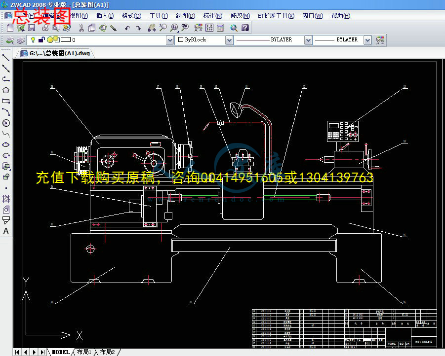
总装图(A1).dwg
横向进给(A0).dwg
滚珠丝杆.dwg
电路原理图(A1).dwg
纵向进给(A0).dwg
蜗杆(A4).dwg
蜗轮(A4).dwg
压缩包内文档预览:(预览前20页/共34页)
预览图 预览图 预览图 预览图 预览图 预览图 预览图 预览图 预览图 预览图 预览图 预览图 预览图 预览图 预览图 预览图 预览图 预览图 预览图 预览图
编号:449079    类型:共享资源    大小:2.33MB    格式:RAR    上传时间:2015-07-05 上传人:好资料QQ****51605 IP属地:江苏
45
积分
关 键 词:
ca6140 普通 车床 数控 技术改造 全套 cad 图纸 毕业 答辩 论文
资源描述:

目录

前言1

摘要5

Abstract6

第一章 绪论7

一 数控系统发展及趋势7

(一)国内外数控系统发展概况7

(二)数控技术发展趋势7

(三)智能化新一代PCNC数控系统10

二 普通机床数控改造的必要性11

(一)微观看改造的必要性11

(二)宏观看改造的必要性12

三 数控改造的内容及优缺点12

(一)国外改造业的兴起12

(二)数控化改造的内容13

(三)机床数控化改造的优缺点13

四 数控机床机构组成、特点及分类14

(一)数控机床的组成14

(二)数控机床机构的特点16

(三)数控机床的分类19

五 普通机床数控化改造市场22

(一)改造的市场22

(二)进口设备和生产线的数控化改造市场22

第二章 C6140普通车床数改的总体方案24

一 总体方案24

(一)主传动系统和进给系统的改造24

(二)主轴脉冲发生器25

(三)主轴脉冲发生器的结构及原理26

第三章 数改C6140车床传动装置设计27

一 滚珠丝杠螺母副27

(一)滚珠丝杠副的工作原理、特点及类型28

(二)滚珠丝杠副的结构29

二 纵向进给系统的设计与计算32

(一)纵向进给系统的设计计算32

(二)滚珠丝杠设计计算34

(三)齿轮及转距的有关计算39

三 横向进给系统的设计与计算42

(一)横向进给系统的设计计算43

(二)滚珠丝杠设计计算44

(三)齿轮及转矩有关计算46

四 滚珠丝杠副轴向间隙的调整和预紧方法47

五 滚珠丝杠副的安装结构50

(一)支承结构50

六 进给系统传动齿轮间隙的消除51

(一)采用减速箱的目的及注意事项51

(二)减少或消除空程的必要性和方法51

第四章 数改C6140自动刀架设计53

一 自动刀架的分类53

二 自动刀架的设计53

第五章 数改6140步进电机的设计56

一 步进电机的工作方式56

二 步进电机的选择56

(一)步进电机选用的基本原则56

(二)数改C6140纵向进给系统步进电机的确定58

(三)数改C6140横向进给系统步进电机的确定58

第六章 数改6140车床导轨设计60

一 导轨的作用60

二 塑料导轨软带60

第七章 数控系统硬件电路设计63

一 数控系统基本硬件组成63

二 单板机控制系统的设计64

第八章 CA6140生产成本及经济技术分析66

第九章 结 论67

参考文献68

专题:70

高速切削的刀具材料及切削技术的应用70

附录Ⅰ:外文文献79

Numerical Control79

附录Ⅱ:中文翻译92

数字控制92

致   谢104


摘要

我国是世界上机床产量最多的国家,但数控机床的产品竞争力在国际市场中仍处于较低水平,即使在国内市场也面临着严峻的形势:一方面国内市场对各类机床产品特别是数控机床有大量的需求,而另一方面却有不少国产机床滞销积压,国外机床产品充斥市场,严重影响我国数控机床自主发展的势头。这种现象的出现,除了有经营上、产品质量上和促销手段上等的原因外,一个最主要的原因就是新产品(包括基型、变型和专用机床)的开发周期长,不能及时针对用户的需求提供满意的产品。

普通机床的数控化改造事业方兴未艾,在我国目前形式下将大批故障机床尤其是一大批闲置的普通机床进行改造、升级,以较小的投入尽快使这批设备在经济发展中发挥效能、创造效益,的确是许多企业的一项不可忽视的课题。


关键词:  脉冲发生器  滚珠丝杠  滚珠丝杠螺母副   自动刀架  

塑料导轨软带


Abstract

My national yes machine output mos statet state in the world,the product competitive power at international market suffer still get off to inferiority level , of the therefor numerically-controlled machine , granted that at home market too be faced with austere posture:on the one hand domestic market versus all manner of tool product especially numerically-controlled machine be covered with demand,whereas on the other hand refuse have got not a little made in one's country tool dull sale overstock,abroad tool product overflow market,had a strong impact on me national numerically-controlled machine independence extend momenta into.show such phenomenal face,except to have got manage upper, product quality upper sum sales promotion instrument good cause besides,the development cycle length of the both one upmost cause namely novelty(include fundamental mode, derivative and special machine),be be incapable of in season aim at user's demand supply satisfied product.

General machine tool 'numerical control melt reclaim undertaking be in the ascendant from, upratein our country for the moment form down move in bulk malfunction tool above all crowd idle general machine tool proceed rebuild, up upgrade,withal lesser project into as soon as possible gotten these batch EQUIPment at economic development exert EFFiciency, create benefit,the one term nonnegligible problem of the forsooth yes heap enterprise.

Keywords:   Impulse generator  Ball screw  Ball screw nut deputy

Automatism knife rest  Plastic rack soft strap

第一章 绪论

一 数控系统发展及趋势

(一)国内外数控系统发展概况

   随着计算机技术的高速发展,传统的制造业开始了根本性变革,各工业发达国家投入巨资,对现代制造技术进行研究开发,提出了全新的制造模式。在现代制造系统中,数控技术是关键技术,它集微电子、计算机、信息处理、自动检测、自动控制等高新技术于一体,具有高精度、高效率、柔性自动化等特点,对制造业实现柔性自动化、集成化、智能化起着举足轻重的作用。目前,数控技术正在发生根本性变革,由专用型封闭式开环控制模式向通用型开放式实时动态全闭环控制模式发展。在集成化基础上,数控系统实现了超薄型、超小型化;在智能化基础上,综合了计算机、多媒体、模糊控制、神经网络等多学科技术,数控系统实现了高速、高精、高效控制,加工过程中可以自动修正、调节与补偿各项参数,实现了在线诊断和智能化故障处理;在网络化基础上,CAD/CAM与数控系统集成为一体,机床联网,实现了中央集中控制的群控加工。

   长期以来,我国的数控系统为传统的封闭式体系结构,CNC只能作为非智能的机床运动控制器。加工过程变量根据经验以固定参数形式事先设定,加工程序在实际加工前用手工方式或通过CAD/CAM及自动编程系统进行编制。CAD/CAM和CNC之间没有反馈控制环节,整个制造过程中CNC只是一个封闭式的开环执行机构。在复杂环境以及多变条件下,加工过程中的刀具组合、工件材料、主轴转速、进给速率、刀具轨迹、切削深度、步长、加工余量等加工参数,无法在现场环境下根据外部干扰和随机因素实时动态调整,更无法通过反馈控制环节随机修正CAD/CAM中的设定量,因而影响CNC的工作效率和产品加工质量。由此可见,传统CNC系统的这种固定程序控制模式和封闭式体系结构,限制了CNC向多变量智能化控制发展,已不适应日益复杂的制造过程,因此,对数控技术实行变革势在必行。

内容简介:
1 专题: 高速切削的刀具材料及切削技术的应用 一、前言 高速切削的研究历史,可以追溯到二十世纪 30 年代由德国 Carl Salomon 博士首次提出的有关高速切削的概念。 Salomon 博士的研究突破了传统切削理论对切削热的认识,认为切削热只是在传统切削速度范围内是与切削速度成单调增函数关系。而当切削速度突破一定限度以后,切削温度不再随切削速度的增加而增加,反而会随切削速度的增加而降低,即与切削速度在较高速度的范围内成单调减函数。 Salomon 博士的研究因第二次世界大战而中断。 50 年代后期开始,高速切削的试 验又开始进入各种试验研究,高速切削的机理开始被科学家们所认识。 1979 年开始由德国政府研究技术部资助、德国 Darmstadt 大学 PTW 研究所牵头、由大学研究机构、机床制造商、刀具制造商、用户等多方面共同组成的研究团队对高速铣削展开了系统的研究。除了高速切削机理外,研究团队同步研究解决高速铣削中机床、刀具、工艺参数等多方面的应用解决方案,使高速铣削在加工机理尚未得到完全共识的情况下首先在铝合金加工和硬材料加工等领域得到应用,解决模具、汽车、航空等领域的加工需求,从而取得了巨大的经济效益。 根据 1992 年国际生产工程研究会 (CIRP)年会主题报告的定义,高速切削通常指切削速度超过传统切削速度 5 10 倍的切削加工。因此,根据加工材料的不同和加工方式的不同,高速切削的切削速度范围也不同。高速切削包括高速铣削、高速车削、高速钻孔与高速车铣等,但绝大部分应用是高速铣削。目前,加工铝合金已达到 2000 7500m/min;铸铁为 900 5000m/min;钢为 600 3000m/min;耐热镍基合金达 500m/min;钛合金达 150 1000m/min;纤维增强塑料为 2000 9000m/min。 二、高速切削的特 点 实践表明,高速切削具有以下加工特点: 切削力降低 ; nts 2 工件热变形减少 ; 有利于保证零件的尺寸、形位精度 ; 已加工表面质量高 ; 工艺系统振动减小 ; 显著提高材料切除率 ; 加工成本降低 ; 高速切削的上述特点,反映了在其适用领域内,能够满足效率、质量和成本越来越高的要求,同时,解决了三维曲面形状高效精密加工问题,并为硬材料和薄壁件加工提供了新的解决方案。 三 、高速切削加工刀具材料选用 铝合金 易切削铝合金 该材料在航空航天工业应用较多,适用的刀具有 K10、 K20、 PCD,切削速 度在 2000 4000m/min,进给量在 3 12m/min,刀具前角为 12 18 ,后角为 10 18 ,刃倾角可达 25 。 铸铝合金 铸铝合金根据其 Si 含量的不同,选用的刀具也不同,对 Si含量小于12%的铸铝合金可采用 K10、 Si3N4 刀具,当 Si 含量大于 12%时,可采用 PKD(人造金刚石 )、 PCD(聚晶金刚石 )及 CVD 金刚石涂层刀具。对于 Si 含量达 16%18%的过硅铝合金,最好采用 PCD 或 CVD 金刚石涂层刀具,其切削速度可在1100m/min,进给量为 0.125mm/r。 铸铁 对铸件,切削速度大于 350m/min 时,称为高速加工,切削速度对刀具的选用有较大影响。当切削速度低于 750m/min 时,可选用涂层硬质合金、金属陶瓷;切削速度在 510 2000m/min 时,可选用 Si3N4 陶瓷刀具;切削速度在 2000 4500m/min 时,可使用 CBN 刀具。 铸件的金相组织对高速切削刀具的选用有一定影响,加工以珠光体为主的铸件在切削速度大于 500m/min 时,可使用 CBN 或 Si3N4,当以铁素体为主时,由于扩散磨损的原因,使刀具磨损严重,不宜使用 CBN,而应采用陶瓷刀具 。如粘结相为金属 Co,晶粒尺寸平均为 3m , CBN含量大于 90% 95%的 BZN6000在 V=700m/min 时,宜加工高铁素体含量的灰铸铁。粘结相为陶瓷 (AlNnts 3 AlB2)、晶粒尺寸平均为 10m 、 CBN 含量为 90% 95%的 Amborite 刀片,在加工高珠光体含量的灰铸铁时,在切削速度小于 1100m/min 时,随切削速度的增加,刀具寿命也增加。 普通钢 切削速度对钢的表面质量有较大的影响,根据德国 Darmstadt 大学PTW 所的研究,其最佳切削速度为 500 800m/min。 目前,涂层硬质合金、金属陶瓷、非金属陶瓷、 CBN 刀具均可作为高速切削钢件的刀具材料。其中涂层硬质合金可用切削液。用 PVD涂层方法生产的 TiN 涂层刀具其耐磨性能比用 CVD 涂层法生产的涂层刀具要好,因为前者可很好地保持刃口形状,使加工零件获得较高的精度和表面质量。 金属陶瓷刀具占日本刀具市场的 30%,以 TiC-Ni-Mo 为基体的金属陶瓷化学稳定性好,但抗弯强度及导热性差,适于切削速度在 400 800m/min 的小进给量、小切深的精加工; Carboly 公司用 TiCN 作为基体、结合剂中少钼多钨的金属陶瓷将强度 和耐磨两者结合起来, Kyocera 公司用 TiN 来增加金属陶瓷的韧性,其加工钢或铸铁的切深可达 2 3mm。 CBN 可用于铣削含有微量或不含铁素体组织的轴承钢或淬硬钢。 高硬度钢 高硬度钢 (HRC40 70)的高速切削刀具可用金属陶瓷、陶瓷、 TiC 涂层硬质合金、 PCBN 等。 金属陶瓷可用基本成分为 TiC 添加 TiN 的金属陶瓷,其硬度和断裂韧性与硬质合金大致相当,而导热系数不到硬质合金的 1/10,并具有优异的耐氧化性、抗粘结性和耐磨性。另外其高温下机械性能好,与钢的亲和力小,适合于中高速 (在 200m/min 左右 )的模具钢 SKD 加工。金属陶瓷尤其适合于切槽加工。 采用陶瓷刀具可切削硬度达 HRC63 的工件材料,如进行工件淬火后再切削,实现 “ 以切代磨 ” 。切削淬火硬度达 HRC48 58 的 45 钢时,切削速度可取 150 180m/min,进给量在 0.3 0.4min/r,切深可取 2 4mm。粒度在1m , TiC 含量在 20% 30%的 Al2O3-TiC 陶瓷刀具,在切削速度为 100m/min左右时,可用于加工具有较高抗剥落性能的高硬度钢。 当切削速度高于 1000m/min 时, PCBN 是最佳 刀具材料, CBN含量大于90%的 PCBN 刀具适合加工淬硬工具钢 (如 HRC55 的 H13 工具钢 )。 高温镍基合金 Inconel 718 镍基合金是典型的难加工材料,具有较高的高温强度、nts 4 动态剪切强度,热扩散系数较小,切削时易产生加工硬化,这将导致刀具切削区温度高、磨损速度加快。高速切削该合金时,主要使用陶瓷和 CBN 刀具。 碳化硅晶须增强氧化铝陶瓷在 100 300m/min 时可获得较长的刀具寿命,切削速度高于 500m/min 时,添加 TiC 氧化铝陶瓷刀具磨损较小,而在100 300m/min时其缺口磨损较大。氮化硅陶瓷 (Si3N4)也可用于 Inconel 718合金的加工。 加拿大学者 M.A.Elbestawi认为, SiC晶须增强陶瓷加工 Inconel 718的最佳切削条件为:切削速度 700m/min,切深为 1 2mm,进给量为 0.10.18mm/z。 氮氧化硅铝 (Sialon)陶瓷韧性很高,适合于切削过固溶处理的Inconel 718(HRC45)合金, Al2O3-SiC 晶须增强陶瓷适合于加工硬度低的镍基合金。 钛合金 (Ti6Al6V2Sn) 钛 合金强度、冲击韧性大,硬度稍低于 Inconel 718,但其加工硬化非常严重,故在切削加工时出现温度高、刀具磨损严重的现象。日本学者T.Kitagawa 等经过大量实验得出,用直径 10mm 的硬质合金 K10 两刃螺旋铣刀 (螺旋角为 30) 高速铣削钛合金,可达到满意的刀具寿命,切削速度可高达 628m/min,每齿进给量可取 0.06 0.12mm/z,连续高速车削钛合金的切削速度不宜超过 200m/min。 复合材料 航天用的先进复合材料 (如 Kevlar 和石墨类复合材料 ),以往用硬质合金和 PCD, 硬质合金的切削速度受到限制,而在 900 以上高温下 PCD 刀片与硬质合金或高速钢刀体焊接处熔化,用陶瓷刀具则可实现 300m/min 左右的高速切削。 四、高速切削刀具技术 高速切削刀具不仅在耐用度和可靠性方面比常规加工有更高的要求,在刀具系统的安全性方面也有特殊的要求。 nts 5 图 3 刀具伸出量对耐用度的影响 从提高耐用度和可靠性角度, 需要考虑: 刀具基体与涂层材料 刀尖几何结构 刀刃数和刀杆伸出量 切削用量 走刀方式 冷却条件 刀具与工件材料匹配从提高使用安全性方面,需要考虑: 刀具系统强度与尺寸 刀杆与机床的夹持方式 刀片夹紧方式 刀具动平衡 nts 6 图 4 球头铁刀不同铣削方式对耐用度的影响 由于高速切削高转速和快进给等特点,除了良好的耐磨性和高的强度韧性的 先进刀具材料,优良的刀具涂层技术,合理的几何结构参数和高同心度的刀刃精度质量等因素外,还需特别注意其它因素对刀具耐用度的影响。图 3 为不同刀具伸出量对切削路径长度的影响,可见伸出量越短,耐用度越高。一般情况下,顺铣的耐用度高于逆铣,而往复铣的耐用度最低 (见图 4)。图 4 中向下进实际反映刀具顶着进给方向进刀,而向上进反映刀具拖着进给方向进刀,对耐用度也有较大影响。铝合金高速铣削通常用双刃铣刀,过多的刀刃会减少容屑空间,容易引起切屑粘刀。为避开共振频率,也可采用三刃铣刀以增加冲击频率。铝合金加工容易产生积屑瘤,这对 高速铣削非常有害。要减少积屑瘤的产生,刀具表面要平滑;避免采用物理气相沉积 (PVD)涂层刀具,因为 TiAlN 涂层很易与铝产生化学反应,可以选用非涂层刀具,细晶金刚石涂层或类金刚石涂层刀具;如有可能,尽量采用油雾刀具内冷进行冷却润滑。 nts 7 高速铣削刀具结构对刀具耐用度和安全性均有很大影响,关键要点包括刀具系统的平衡设计;减少径向和轴向跳动;控制动平衡精度;与机床联接普遍采用 HSK 刀柄或类似双面接触短锥刀柄;刀具的夹紧最新趋势是采用冷缩式夹紧结构 (或称热装式 ),装夹时利用感应或热风加热使刀杆孔膨胀,取出旧刀 具,装入新刀具,然后采用风冷使刀具冷却到室温,利用刀杆孔与刀具外径的过盈配合夹紧,这种结构刀具的径向跳动在 4m ,刚性高,动平衡性好,夹紧力大,高转速下仍能保持高的夹紧可靠性,特别适用于更高转速的高速铣削加工。 五、高速切削工艺技术 高速切削工艺主要包括:适合高速切削的加工走刀方式,专门的CAD/CAM 编程策略,优化的高速加工参数,充分冷却润滑并具有环保特性的冷却方式等等。 高速切削的加工方式原则上多采用分层环切加工。直接垂直向下进刀极易出现崩刃现象,不宜采用。斜线轨迹进刀方式的铣削力是逐渐 加大的,因此对刀具和主轴的冲击比垂直下刀小,可明显减少下刀崩刃的现象。螺旋式轨迹进刀方式采用螺旋向下切入,最适合型腔高速加工的需要。 CAD/CAM 编程原则是尽可能保持恒定的刀具载荷,把进结速率变化降到最低,使程序处理速度最大化。主要方法有:尽可能减少程序块,提高程序处理速度;在程序段中可加人一些圆弧过渡段,尽可能减少速度的急剧变化;粗加工不是简单的去除材料,要注意保证本工序和后续工序加工余量均匀,尽可能减少铣削负荷的变化;多采用分层顺铣方式;切入和切出尽量采用连续的螺旋和圆弧轨迹进行切向进刀,以保 证恒定的切削条件;充分利用数控系统提供的仿真验证的功能。零件在加工前必须经过仿真,验证 刀位数据的正确性, 刀具各部位是否与零件发生干涉, 刀具与夹具附件是否发生碰撞,确保产品质量和操作安全。 nts 8 高速铣削加工用量的确定主要考虑加工效率、加工表面质量、刀具磨损以及加工成本。不同刀具加工不同工件材料时,加工用量会有很大差异,目前尚无完整的加工数据。通常,随着切削速度的提高,加工效率提高,刀具磨损加剧,除较高的每齿进给量外,加工表面粗糙度随切削速度提高而降低。对于刀具寿命,每齿进给量和轴向切深均存在最佳值, 而且最佳值的范围相对较窄。高速铣削参数一般的选择原则是高的切削速度、中等的每齿进给量 fz、较小的轴向切深 ap 和适当大的径向切深 ae。 在高速铣削时由于金属去除率和切削热的增加,冷削介质必须具备将切屑快速冲离工件、降低切削热和增加切削界面润滑的能力。常规的冷却液及加注方式很难进入加工区域,反而会加大铣刀刃在切入切出过程的温度变化,产生热疲劳,降低刀具寿命和可靠性。现代刀具材料,如硬质合金、涂层刀具、陶瓷和金属陶瓷、 CBN 等具有较高的红硬性,如果不能解决热疲劳问题,可不使用冷却液。 微量油雾冷却 一方面可以减小刀具切屑工件之间的摩擦,另一方面细小的油雾粒子在接触到刀具表面时快速气化的换热效果较冷却液热传导的换热效果方式能带走更多的热量,目前已成为高速切削首选的冷却介质。 氮气油雾冷却介质在钛合金的高速铣削中取得了很好的效果。氮气油雾冷却介质除具有空气油雾的冷却润滑作用外,还具有抗氧化磨损等作用,在 33m/min 的铣削速度时,相比较空气油雾冷却,刀具耐用度提高 60%,铣削力可降低 20% 30%。 六、结语 高速切削是一项先进的、正在发展的综合技术,必须将高性能的高速切削机床、与工件 材料相适应的刀具和对于具体加工对象最佳的加工工艺技术相结合,充分发挥高速切削技术的优势。高速切削工具技术也是一项关键技术,为了适应和推动我国高速切削技术的发展,我们应该充分认识到,工具制造是一个高技术含量的行业,应加强该领域的基础研究、工程研究和应用研究;迅速发展的高速切削技术极大的刺激高性能刀具的需求,我国工具nts 9 行业应重点在刀具的耐磨性、精度和可靠性方面加强研发力度,提高刀具的竞争能力;刀具的竞争力应集中在高性能带来的整体经济效益,在应用领域推广使用高性能刀具;提供个性化技术服务;根据我国目前的实际情况,建议重点发展涂层技术 (如耐磨 (硬、软 )涂层、复合涂层、纳米结构涂层等 ),刀具质量保障技术和刀具数据库。 nts 10 附录 :外文文献 Numerical Control One of the most fundamental concepts in the area of advanced manufacturing technologies is numerical control. Controlling a machine tool using a punched tape or stored program is known as numerical control (NC). NC has been defined by the Electronic Industries Association (EIA) as “ a system in which actions are controlled by the direct insertion of numerical dada at some point .the system must automatically interpret at least some portion of this data.” the numerical data required to produce a part is known as a part program. A numerical control machine tool system contains a machine control unit (MCU) and the machine tool itself. The MCU is further divided into two elements: the data processing unit (DPU) and the control loops unit (CLU). The DPU processes the coded data from the tape or other media and passes information on the potions of each axis, required direction of motion, feed rate, and auxiliary function control signals to the CLU. The CLU operates the drive mechanisms of the machine, receives feed back signals concerning the actual position and velocity of each of the axes, and signals the completion of operation. The DPU sequentially reads the data. When each line has completed execution as noted by the CLU, anther line of data is read. A data processing units consists of some or all of the following parts: 1) Data input device such as a paper tape reader, magnetic tape reader, RS232-C port, etc 2) Data-reading circuits and parity-checking logic 3) Decoding circuits for distributing data among the controlled axes 4) An interpolator, which supplies machine-motion commands between data points for tool motion A control loops unit, on the other hand consists of the following: 1) Position control loops for all the axes of motion, where each axis has a separate control loop 2) Velocity control loops, where feed control is required nts 11 3) Deceleration and backlash take up circuits 4) Auxiliary functions control, such as coolant on/off, gear change, spindle on/off control Geometric and kinematic data are typically fed from the DPU to the CLU. The CLU then governs the physical system based on the data from the DPU. Numerical control was developed to overcome the limitation of human operators, and it has done so. Numerical control machines are more accurate than manually operated machines, they can produce parts more uniformly, they are faster, and the long-run tooling costs are lower. The development of NC led to the development of several other innovations in manufacturing technology: Electric discharge machining Laser-cutting Electron beam welding Numerical control has also made machine tools more versatile than their manually operated predecessors. An NC machine tool can automatically produce a wide variety of parts, each involving an assortment of widely varied and complex machining processes. Numerical control has allowed manufacturers to undertake the production of products that would not have been feasible from an economic perspective using manually controlled machine tools and processes. Historical Development of NC Like so many advanced technologies, NC was born in the laboratories of the Massachusetts Institute of Technology. The concept of NC was developed in the early 1950s with funding provided by the U.S. Air Force. In its earliest stages, NC machines were able to make straight cuts efficiently and effectively. However, curved paths were a problem because the machine tool had to be programmed to undertake a series of horizontal and vertical steps to produce a curve. The shorter the straight lines making up the steps, the smoother is the curve. Each line segment in the steps shown in the close up in Fig.2.17 had to be calculated. This was a cumbersome approach that had to be overcome if NC was to develop further. This problem led to the development in 1959 of the Automatically Programmed Tools (APT) language. This is a special programming language for nts 12 NC that uses statements similar to English language to define the part geometry, describe the cutting tool configuration, and specify the necessary motions. The development of the APT language was a major step forward in the development of NC technology. The original NC systems were vastly different from those used today. The machines had hardwired logic circuits. The instructional programs were written on punched paper, which was later to be replaced by magnetic plastic tape. A tape reader was used to interpret the instructions written on the tape for the machine. Together, all of this represented a giant step forward in the control of machine tools. However, there were a number of problems with NC at this point in its development. A major problem was the fragility of the punched paper tape medium. It was common for the paper containing the programmed instructions to break or tear during a machining process. This problem was exacerbated by the fact that each successive time a part was produced on a machine tool, the paper tape carrying the programmed instructions had to be rerun through the reader. If it was necessary to produce 100 copies of a given part, it was also necessary to run the paper tape through the reader 100 separate times. Fragile paper tapes simply could not withstand the rigors of a shot floor environment and this kind of repeated use. This led to the development of a special magnetic plastic tape. Whereas the paper tape carried the programmed instructions as a series of holes punched in the tape, the plastic tape carried the instructions as a series of magnetic dots. The plastic tape was much stronger than the paper tape, which solved the problem of frequent tearing and breakage. However, it still left two other problems. The most important of those was that it was difficult or impossible to change the instructions entered on the tape. To make even the most minor adjustments in a program of instructions, it was necessary to interrupt machining operations and make a new tape. It was also still necessary to run the tape through the reader as many times as there were parts to be produced. Fortunately, computer technology became a reality and soon solved the problem of NC associated with punched paper and plastic tape. 1) Advent of Direct Numerical Control nts 13 The development of a concept known as direct numerical control (DNC) solved the paper and plastic tape problems associated with numerical control by simply eliminating tape as the medium for carrying the programmed instructions. In direct numerical control, machine tools are tied, via a data transmission link, to a host computer (Fig 2.18). Programs for operating the machine tools are stored in the host computer and fed to the machine tool as needed via the data transmission linkage. Direct numerical control represented a major step forward over punched tape and plastic tape. However, it is subject to the same limitations as all technologies that depend on a host computer, the machine tools also experience downtime. This problem led to the development of computer numerical control. 2) Advent of Computer Numerical Control The development of the microprocessor allowed for the development of programmable logic controllers (PLCs) and microcomputer. These two technologies allowed for the development of computer numerical control (CNC). With CNC, each machine tool has a PLC or a microcomputer that serves the purpose. This allows programs to be input and stored at each individual machine tool. It also allows programs to be developed off-line and downloaded at the individual machine tool. CNC solved the problems associated with downtime of the host computer, but it introduced another problem known as data management. This is a problem all work settings dependent on microcomputers have. The same program might be loaded on ten different microcomputers with no communication among them. This problem is the process of being solved by local area networks that connect microcomputers for better data management. The problem of data management led to the development of distributed numerical control. 3) Advent of Distributed Numerical Control Distributed numerical control (also called DNC) takes advantage of the best aspects of direct numerical control and computer numerical control. With distributed numerical control there are both host computers and local computers at the individual machine tools (Fig 2.19). This allows the programs to be stored nts 14 in the host computers and, thereby, better managed. However, it also allows them to be downloaded to local microcomputers or PLCs. It also allows for local input and interaction through microcomputers or PLCs at the machine levels. NC Machine Components There are four components in any NC machine: The actual NC tool The machine control unit (MCU) The communication interface between the NC machine and the MCU A variety of accessories for performing specific jobs on the NC machine The actual NC machine may be a milling machine, lathe, drill, or any other type of machine tool. The MCU is the control unit that holds the programs that instruct the NC machine. The MCU also has various devices available for operator input. Information contained in the MCU is carried to the activators on the NC machine through the communication interface. These activators receive the electronic signals from the MCU and cause the mechanical apparatus of the NC machine to operate. Less sophisticated NC machines have open-loop activators. An open-loop activator can receive a signal and carry out the instructions contained in that signal, but cannot feed back to the MCU to show that instructions carried in the signal have been properly completed. More sophisticated NC machine use closed-loop activators. A closed-loop activator can receive and carry out a signal and feed data back to the MCU showing that the signal has been carried out and to what extent. The more sophisticated closed-loop systems are been used more and more because they allow closer monitoring and immediate corrective action when problems with executing a program arise. The accessories are special tools required to carry out a specific job. NC Programming These are four ways to program an NC machine: manual programming, digitizing, written programs, and graphic programs (Fig 2.20). Manual programming is the most cumbersome of the four. It involves calculating numerical values that identify tool location and specify tool direction. Once these nts 15 values have been calculated, recorded and feed into the MCU. Digitizing is a process frequently used in computer-aided design and drafting, whereby a drawing of a part is traced electronically. As it is traced, the various points on the drawing are converted into X-Y coordinates and stored in the computer. Once the drawing has been completely traced, the stored X-Y coordinates define the part and can be fed to an NC machine to provide instructions on tool positioning and movement. Written programs are similar to those developed for use with any computer. With such programs, English language-type statements are written to describe tool positions and movement, as well as speed and feed rates. Such programs are fed into the MCU, where they are translated into machine language and forwarded to the NC machines activators. The most modern, sophisticated method of programming an NC machine is by using a three-dimensional model of the part to provide the data that guide the NC machine in producing the part. As NC technology continues to develop, this programming method will eventually be used more than any other. Classifications of NC Machines Numerical control machines are classified in different ways. An early method was to categorize them as being either point-to-point or continues-path machines. Point-to-point machines, as the name implies, move in a series of steps from one point to the next (Fig 2.21)
温馨提示:
1: 本站所有资源如无特殊说明,都需要本地电脑安装OFFICE2007和PDF阅读器。图纸软件为CAD,CAXA,PROE,UG,SolidWorks等.压缩文件请下载最新的WinRAR软件解压。
2: 本站的文档不包含任何第三方提供的附件图纸等,如果需要附件,请联系上传者。文件的所有权益归上传用户所有。
3.本站RAR压缩包中若带图纸,网页内容里面会有图纸预览,若没有图纸预览就没有图纸。
4. 未经权益所有人同意不得将文件中的内容挪作商业或盈利用途。
5. 人人文库网仅提供信息存储空间,仅对用户上传内容的表现方式做保护处理,对用户上传分享的文档内容本身不做任何修改或编辑,并不能对任何下载内容负责。
6. 下载文件中如有侵权或不适当内容,请与我们联系,我们立即纠正。
7. 本站不保证下载资源的准确性、安全性和完整性, 同时也不承担用户因使用这些下载资源对自己和他人造成任何形式的伤害或损失。
提示  人人文库网所有资源均是用户自行上传分享,仅供网友学习交流,未经上传用户书面授权,请勿作他用。
关于本文
本文标题:CA6140普通车床的数控技术改造设计【8张CAD图纸+毕业答辩论文】
链接地址:https://www.renrendoc.com/p-449079.html

官方联系方式

2:不支持迅雷下载,请使用浏览器下载   
3:不支持QQ浏览器下载,请用其他浏览器   
4:下载后的文档和图纸-无水印   
5:文档经过压缩,下载后原文更清晰   
关于我们 - 网站声明 - 网站地图 - 资源地图 - 友情链接 - 网站客服 - 联系我们

网站客服QQ:2881952447     

copyright@ 2020-2025  renrendoc.com 人人文库版权所有   联系电话:400-852-1180

备案号:蜀ICP备2022000484号-2       经营许可证: 川B2-20220663       公网安备川公网安备: 51019002004831号

本站为文档C2C交易模式,即用户上传的文档直接被用户下载,本站只是中间服务平台,本站所有文档下载所得的收益归上传人(含作者)所有。人人文库网仅提供信息存储空间,仅对用户上传内容的表现方式做保护处理,对上载内容本身不做任何修改或编辑。若文档所含内容侵犯了您的版权或隐私,请立即通知人人文库网,我们立即给予删除!