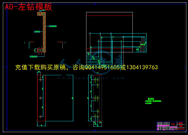
包缝机机体钻孔组合机床总体及夹具设计
摘要:本设计课题来源于盐城市江淮动力集团。为了提高加工精度和生产效率,需要设计一种组合机床来改善加工情况。本组合机床是针对工件左面上钻4个φ5、4个φ4.2、3个φ3.3深度不一的11个孔和右面1钻φ3.3深度不一的9个孔而设计的。该设计的内容重点是总体设计和夹具设计两方面。在加工工艺路线方案中,确定装料高度,确定加工线各系列机床的基本类型及机床配置形式,确定机床部件型号及机床夹具,完成了“三图一卡”的绘制及夹具的设计。“三图一卡”主要根据自己计算切削力,切削转矩等选择相应的机床部件。而夹具设计,用 “一面两孔”定位方案消除工件的六个自由度,使工件获得稳定可靠的定位。工件夹紧装置则选用结构简单、可靠、方便的螺旋夹紧装置,使夹紧平稳可靠。该机床满足设计的要求。
关键词:组合机床;夹具;
The Overall and Fixture Design of Modular Machine Tool for Drilling Holes of BAO Sewing Machine
Abstract: The design project is from Jiangdong Group, Yancheng. In order to improve the accuracy and efficiency, it is necessary to design a modular machine tool. The machine tool is designed for the synchronous processing of four φ5 holes, four φ4.2 holes, three φ3.3 left holes of varying depth of 11 holes , and nineφ3.3 right holes of verying depth . The design is mainly focused on both the overall design and jig design. In the processing line programe ,We must establish a high degree of putting the workpiece and identify the basic types of machine tools and the configuration types of machine tools , we are also determine the kinds of parts and fixture , Meanwhile the drawing of “Three Charts and One Card” (automatic drawing process chart, size relation chart, machining schematic diagram and production calculating card) and fixture design are completed. “Three Charts and One Card” are based mainly on its own calculation of cutting force ,cutting torque and other machine tool parts .As far as jigs are concered, with the aid of one platform and two bore according to the principle of six points positioning to eliminate the six degrees of freedom of workpiece for a stable and reliable positioning, and the synchronous processing of two surfaces of parts which can simplifying the process. Simple, reliable and convenient spiral grip devices are employed for a stable and reliable grip. The Modular Machine Tool can satisfy for the requirements of the design .
Key Words: Modular machine tool; Fixture;
目 录
1 前言1
2 组合机床总体设计3
2.1 总体方案论证3
2.1.1 加工对象工艺性分析3
2.1.2 机床配置型式的选择3
2.1.3 定位基准的选择4
2.2 确定切削用量及选择刀具4
2.2.1 选择切削用量4
2.2.2 计算切削力、切削扭矩及切削功率6
2.2.3 刀具耐用度的计算10
2.2.4 选择刀具结构10
2.3 三图一卡设计10
2.3.1 被加工零件工序图10
2.3.2 加工示意图11
2.3.3 机床联系尺寸图12
2.3.4 机床生产率计算卡15
3 组合机床夹具设计17
3.1 零件的工艺性分析17
3.1.1 夹具设计的基本要求17
3.1.2 夹具总体结构构思17
3.2 定位方案的确定18
3.2.1 定位方案的论证18
3.2.2 定位基准的选择18
3.2.3 定位的实现方法18
3.3 夹紧方案确定20
3.3.1夹紧装置的确定20
3.3.2夹紧力的确定21
3.4 导向装置的选择22
3.4.1钻模套型式的选择和设计22
3.4.2钻模板的类型和设计23
3.5 误差分析24
3.5.1 影响加工精度的因素24
3.5.2 保证加工精度的条件25
3.6 夹具体确定26
4 结论27
参考文献28
致 谢29
附 录30
1 前言
组合机床是根据工件加工需要,以大量通用部件为基础,配以少量专用部件组成的一种高效的专用机床。组合机床通常是多刀、多面、多工序、多工位加工,使用继电器- 接触器控制,电气线路复杂,故障率高,操作人员的维修任务重,设备的使用率低在组合机床的诸多零件中,主轴箱是组合机床设计过程中工作量最大的部件,因为通常主轴箱是采用一根动力轴带动多根主轴的工作方式,各传动轴必须在有限的标准箱体空间中找到适宜的分布位置并避免干涉,而各轴的设计又必须保证其转速、旋向、强度和刚度,因此难度大、设计周期长。在批量设计某生产线的组合机床主轴箱中,为提高设计质量,缩短设计周期,我们采用计算机辅助设计组合机床主轴箱,取得了良好的技术经济效果。组合机床的分类繁多,有大型组合机床和小型组合机床,有单面、双面、三面、卧式、立式、倾斜式、复合式,还有多工位回转台式组合机床等;如卧式单面多孔加工组合机床的液压系统, 可完成自动工作循环: 快进、工进、快退、停止; 能同时驱动多根主轴进行钻孔加工。钻孔时是靠主轴产生的转矩T及主轴的转速n进行钻孔。在钻孔过程中外负载经常是变化的, 当钻头上的负载增大, 即转矩增大时, 要求转速能自动下降, 当钻头上的负载减小, 即转矩减小时, 要求转速能自动升高, 保证钻孔时消耗的功率为恒定值。组合机床主要用于平面加工和孔加工两类工序。随着综合自动化的发展,其工艺范围正扩大到车外圆、行星铣削、拉削、推削、磨削、抛光、冲压等工序。此外,还可以完成焊接、热处理、自动装配和检测、清洗和零件分类及打印等非切削工作。


 川公网安备: 51019002004831号