钢管自动喷标系统之喷标小车的设计开题报告.doc

钢管自动喷标系统之喷标小车的设计【优秀含21张CAD图纸+全套机械毕业设计】

收藏

资源目录
跳过导航链接。
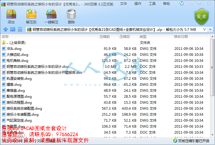
钢管自动喷标系统之喷标小车的设计【优秀含21张CAD图纸+全套机械毕业设计】.zip
钢管自动喷标系统之喷标小车的设计开题报告.doc---(点击预览)
钢管自动喷标系统之喷标小车的设计.doc---(点击预览)
外文翻译--机械运动和动力学.doc---(点击预览)
任务书.doc---(点击预览)
丝杆.dwg
丝杆座.dwg
冲头.dwg
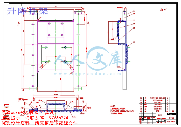
升降托架.dwg
喷标小车装配图.dwg
喷标流程图.dwg
喷标系统总装配图.dwg
大锥齿轮.dwg
小锥齿轮.dwg
手柄轴.dwg
摩擦盘.dwg
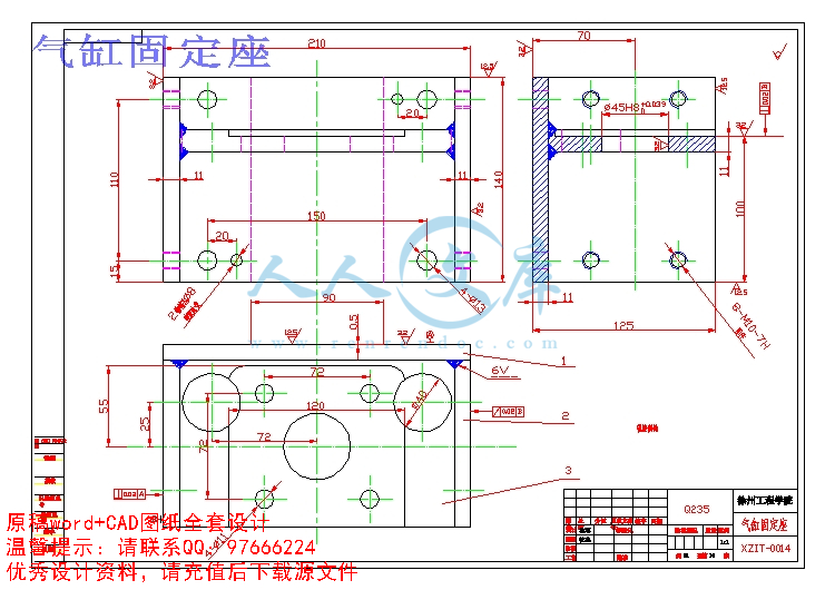
气缸固定座.dwg
气路图.dwg
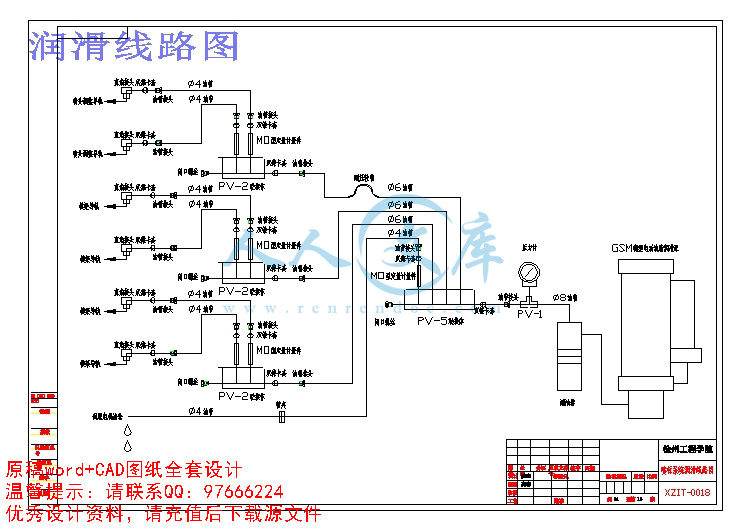
润滑线路图.dwg
电机角铁.dwg
移动支架.dwg
螺套.dwg
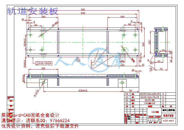
轨道安装板.dwg
轴承座.dwg
配电原理图.dwg
铜螺母.dwg
压缩包内文档预览:
预览图 预览图 预览图 预览图 预览图 预览图
编号:455683    类型:共享资源    大小:3.96MB    格式:ZIP    上传时间:2015-07-11 上传人:小*** IP属地:福建
50
积分
关 键 词:
钢管 自动 系统 小车 设计 优秀 优良 21 cad 图纸 全套 机械 毕业设计
资源描述:

!【详情如下】CAD图纸+word设计说明书.doc[24000字,62页]【需要咨询购买全套设计请加QQ97666224】.bat

丝杆.dwg

丝杆座.dwg

任务书.doc

冲头.dwg

升降托架.dwg

喷标小车装配图.dwg

喷标流程图.dwg

喷标系统总装配图.dwg

外文翻译--机械运动和动力学.doc

大锥齿轮.dwg

小锥齿轮.dwg

手柄轴.dwg

摩擦盘.dwg

气缸固定座.dwg

气路图.dwg

润滑线路图.dwg

电机角铁.dwg

移动支架.dwg

螺套.dwg

轨道安装板.dwg

轴承座.dwg

配电原理图.dwg

钢管自动喷标系统之喷标小车的设计.doc

钢管自动喷标系统之喷标小车的设计【优秀含21张CAD图纸+全套机械毕业设计】.zip

钢管自动喷标系统之喷标小车的设计开题报告.doc

铜螺母.dwg

摘要


钢管是一种多功能的钢材,其用途覆盖了石油、冶金、煤炭、汽车、船舶、电站以及军工等行业,为国家经济建设和国防安全做出了巨大的贡献。本文以国内外钢管生产线上精整区喷标系统的研究与开发现状为背景,对悬臂式钢管喷标系统进行了研究设计。本课题的主要研究工作:

第一章综合叙述了钢管的工艺生产流程及API国际标准;说明了国内喷标系统的开发现状及存在的问题并阐述了开发钢管喷标系统的必要性;陈述了课题的来源以及论文的主要工作和意义。

第二章针对喷标系统设计的总体说明,提出了系统的设计总目标;给出了系统设计的关键参数并给出了系统的平面布置图;根据系统的整体组成结构,对各部分机构及工作过程进行简单说明;最后给出喷标小车机械部分的设计方案以及简要概述喷标控制系统的总体设计。

第三章根据设备运行的要求设计了喷标小车的机械、电气结构,并且对关键部分的设计进行分析。

第四章介绍了喷标控制系统的设计组成,简述了PLC的编程方式,西门子S7400PLC的特点;PLC技术在工业应用中的优势分析以及PLC的硬件设计要求,喷标小车的伺服运动控制原理,最后给出了喷标流程图和相应的PLC程序。

第五章总结喷标系统设计过程所做的工作,并对系统的改进方向进行了展望。


关键词 钢管;喷标;PLC;伺服电机;位置控制

ABSTRACT


Steel tube is widely used as a sort of metallic material in oil,metallurgy,automobile, watercraft, electric plant, war industry and so on. It is important to the national economic development. This dissertation is based on the design and development of the system of steel tencil in home and abroad.with the aim of designing a Cantilever-Stencil Machine for Steel Pipe. the main contents are shown as follows:

In chapter 1,technological process of steel tube and the international standard API are introduced.Then the current situation of research and problems on tencilling system in China are described.And also,the necessities of the improvement of it are explained.Finally,the source of this project and the main contents as well as the significance of this paper are mentioned.

In chapter 2,according to the design target of stencil system,some key design parameters as well as the manufacture flow are put forward.The framework of an integrated tencil system comprising structures is presented,followed by a description of the mechanical struction and interaction.

In chapter 3, the mechanism structure is designed according to the requirement of the equipment function. And the pivotal piece is analyzed.

In chapter 4,PLC program metheod and the characters of S7400 series are introduced in brief.Attention are mainly focused on the modular design of PLC program,the servo-controlling system of the moving structure.flowed by the PLC program is mentioned.

In chapter 5,the work of dissertation is summarized and prospect of improving direction of system is presented.


Key words  steel tube  stencil  PLC  servo motor  position control

目       录


1 绪论1

1.1 钢管喷标系统的开发现状1

1.1.1 引言1

1.1.2 喷标系统的开发现状3

1.2 钢管喷标系统开发的必要性4

1.3 课题来源4

1.4 论文的主要工作和意义4

2 喷标系统总体设计5

2.1 喷标系统设计要求5

2.2 喷标系统总体设计5

2.2.1 喷标小车的机械结构设计5

2.3 喷标系统的控制系统设计7

2.3.1 喷标系统的自动工作过程7

2.4 本章小结8

3 小车机械、电气结构设计9

3.1 横移机构的设计9

3.1.1 齿轮齿条副设计9

3.1.2 滚动直线导轨副设计10

3.1.3 伺服电机的选型14

3.2 喷头升降机构的设计15

3.2.1 选择喷标方式16

3.2.2 气缸的选型18

3.2.3 气缸活塞与喷头的配合18

3.2.4 气缸的固定19

3.3 喷头位置调节机构设计20

3.3.1 滚动直线导轨副21

3.3.2 锥齿轮副设计21

3.3.3 丝杆副设计29

3.4 防撞机构设计29

3.4.1 动作方式30

3.5 气路控制系统设计30

3.5.1 气动回路30

3.6 本章小结32

4 喷标控制系统设计33

4.1 控制系统的组成33

4.2 PLC软件及编程33

4.3 PLC在喷标系统中的应用34

4.3.1 PLC的特点34

4.3.2 PLC在工业应用中的优势34

4.3.3 S7-400编程方式35

4.4 PLC系统的硬件设计36

4.4.1PLC I/O点数统计36

4.5 喷标小车的伺服运动控制37

4.5.1伺服控制系统简介37

4.5.2 伺服运动控制系统工作原理38

4.6 PLC程序设计39

4.6.1 喷标流程39

4.7 配电电气控制40

4.8 本章小结40

5 结论41

致谢42

参考文献43

附录44

附录144

外文原文44

译文部分49

附录254

附录365


1 绪论

1.1 钢管喷标系统的开发现状

1.1.1 引言

钢管是一种用钢制作的具有中空截面而长度远大于外径(或边长)的金属材料。截面通常为圆形,但也可呈扁、方和异型等。钢管的结构特征是:

1)具有封闭的环形横断面;

2)两端开口;

3)管长与外径之比L/D较大;

钢管是一种多功能的经济断面钢材。它在国民经济各部门中的应用愈来愈广泛。

钢管作为输送管广泛地用于输送油、气、水等各种液体,如石油及天然气的钻探开采与输送、锅炉的水与蒸汽管道、一般的水煤气管道等。

钢管作为结构管大量地用于机械制造业和建筑工业,如用于制作房架、塔吊、钢管桩、各种车辆的构架等。在断面面积相同的条件下,钢管比圆钢、方钢等的抗弯能力大,钢性好,其单位体积的重量轻。因此,钢管是一种抗弯能力较强的结构材料。

钢管还作为中空的零件毛坯用于制造滚动轴承、液压支柱、液压缸筒体、空心轴、花键套、螺母以及手表壳等,这既节约金属又节省加工工时。

钢管又是国防工业中的重要材料,如用于制造枪管、炮筒及其他武器。随着航空、火箭、导弹、原子能与宇宙空间技术等的发展,精密、薄壁、高强度等钢管的需求量正迅速增长。

钢管的种类繁多,生产过程复杂,生产设备也很庞大,大型企业一般采用自动化生产线来完成钢管生产的各个工艺流程,一般热轧钢管的生产工艺如下图1-1所示。

参考文献

[1] 梁剑新.基于现场总线的自动喷号机的研制[D].浙江:浙江大学硕士学位论文,2001 .2

[2] 魏爱玉. 钢管MWBPS系统设计及控制软件的开发[D].浙江:浙江大学硕士学位论文,2004.2

[3] 姜晓勇.钢管测长、称重、喷标系统的研究与开发[D].浙江:浙江大学硕士学位论文,2003. 1

[4] 施江肖.WMBPS系统软件设计及测试策略研究[D].浙江:浙江大学硕士学位论文,2003. 1

[5] 唐志峰,项占琴,李明范等.点阵式自动钢管喷标机的研制[J].工程设计,2002

[6] 王彤.机电领域中伺服电机的选择原则[J].应用科技,2001(1)

[7] 西门子.SIMATIC  S7梯形图编程手册[M],1998

[8] Steve Teixera,Xavier Pachcco. Delphi5开发人员指南[M].北京:机械工出版社,2001

[9] 蒋方炎.PLC在工业集散控制系统中的应用[J].电子计算机与外部设备,2000

[10] H-D.Chu and Dobson,Govement Report,PB97-176671,USA,1997

[11] Alan Kilian. Quick and Easy Motor Control, CIRCUIT CELLAR. 2001, 7

[12] Wai, R.-J.; Lee, M.-C.; Intelligent Optimal Control of Single-Link Flexible

Robot Arm, Industrial Electronics, IEEE Transactions on,Volume: 51,Issue:1,Feb. 2004 Pages:201一220

[13] 郭庆鼎,王成元.交流伺服系统[M].北京:机械工业出版社,1993. 6

[14] 沈安文.位置控制系统中电子齿轮实现的简易方法[J].机械与电子,2001

[15] 孙克梅,田中大,王俊.喷绘机位置控制系统设计[M].控制工程,2003. 3

[16] 姚晓光,余强等.微机监控系统中PLC与上位机通信的研究[J].电气自动化,1999. 4

[17] 蔡忠法等.上下位机数据通信的模块化接口技术及应用[J].微计算机信息,2002. 2

[18] 黄锡恺,郑文纬.机械原理[M].北京:高等教育出版社,1989

[19] 濮良贵,纪名刚.机械设计[M].北京:高等教育出版社,1996

[20] 秦曾煌.电工技术[M].北京:高等教育出版社,1993

[21] 宋红晓,项占琴.龙门式钢管喷标机的研制[J].机电一体化技术,2005.7

[22] 罗福兴.龙门式喷标机的研发[D].浙江:浙江大学硕士学位论文,20004.2

[23] OMRON中国有限公司.接近传感器以及光电传感器选型手册[M],2002

[24] 《电气工程师手册》第二版编辑委员会.《电气工程师手册》第二版[M].北京:机械工业出版社,2002.1

[25] 《现代机械传动手册》编辑委员会.《现代机械传动手册》第二版[M].北京:机械工业出版社,2002.3

[26] 《机械设计手册》编委会.《机械设计手册》第三版第2卷[M].北京机械工业出版社,2004.8

[27] 《机械设计手册》编委会.机械设计手册(单行本)零部件设计常用基础标准[M].北京:机械工业出版社,2004.8

[28] 左键民.液压与气压传动[M].北京:机械工业出版社,2005,7

[29] 范思冲.画法几何及机械制图[M].北京:机械工业出版社,2005.9

内容简介:
徐州工程学院 毕业设计(论文)任务书 机电工程学院 学院 机械设计制造及其自动化 专业 设计(论文)题目 钢管喷标系统之喷标小车的设计 学 生 姓 名 沈忠 班 级 04 机本 4 起 止 日 期 2008.2.25 2008.6.2 指 导 教 师 崔增柱 教研室主任 李志 发任务书日期 2008 年 2 月 25 日 1.毕业设计的背景: nts 根据 GB2102-88 规定,外径不小于 36 毫米的钢管及截面长不小于 150 毫米的异 型钢管应在每根钢管一端的端部有喷印、滚印、钢印或粘贴印记。印记应清晰明显, 不易脱落。印记应包括钢的牌号、产品规格、产品标准号和供方印记或注册商标。具 体不同类型的管子有不同的印记内容。 国内一些大型钢铁公司的 产品要参与国际竞争,其产品必须符合国际标准,厂家 必须要加强自身的质量管理和自我保护意识,在自己生产的产品上标识印记,利用喷 码技术对钢管进行产品质量控制和跟踪是发展趋势。于是大型的钢铁公司耗巨资引进 了国外的整条生产线,虽然进口设备测量精度高、生产效率高、可靠性好、工人劳动 强度低、字迹统一规范,但是同时进口设备成本高、要求工人的素质高、维护成本也 高。这就对整个国内钢铁行业带来了新的挑战。 对于钢管行业来讲,钢管喷标是完成此项任务的主要方法,将产品的批次、班号、 材质、钢级、执行标准等有关 信息都喷印在产品上。相对于传统在钢管上打的印记来 说速度快,相对于涂的色带而言,包含的信息量大。面对传统方法的落后性与进口设 备的高成本性之间的矛盾,开发设计钢管喷标系统有着其他设备不可替代的作用。 2.毕业设计 (论文 )的内容和要求: 本论文所设计的钢管喷标系统部件喷标小车,是涉及到多学科,多专业,集机电 和计算机一体化的设备。主要内容有通过对系统开发现状的分析,对喷标系统进行了 总体方案设计;根据总体方案设计了喷标小车的具体机械结构、气路系统、安全防护、 控制系统。通过对系统工作原 理的研究,进行了 PLC 程序的设计。该系统的设计综合 运用了机械、电子、计算机三大知识体系,由于采用了喷头伺服电机拖动的形式,喷 印定位精度得到了提升。 设计要求如下: 1.独立完成设计任务; 2.研究课题的应用前景及发展状况; 3.完 成机械系统的设计计算书、图纸、图表等相关内容; 4.控制系统的流程图、配电图、 输入输出的设计。 3.主要参考文献: nts 1 魏爱玉 . 钢管 MWBPS 系统设计及控制软件的开发 D. 浙江:浙江大学硕士学位论文 ,2004.2 2 唐志峰,项占琴,李明范等 .点阵 式自动钢管喷标机的研制 J.工程设计, 2002 3 濮良贵,纪名刚 .机械设计 M.北京 :高等教育出版社, 1996 4 现代机械传动手册编辑委员会 .现代机械传动手册第二版 M.北京:机械工业出版社, 2002.3 5 机械设计手册编委会 .机械设计手册第三版第 2卷 M.北京机械工业出版社, 2004.8 6 机械设计手册编委会 .机械设计手册(单行本)零部件设计常用基础标准 M.北京:机械工业出版社, 2004.8 7 西门子 .SIMATIC S7梯形图编程 手册 M,1998 8 蒋方炎 .PLC在工业集散控制系统中的应用 J.电子计算机与外部设备 ,2000 9 孙克梅,田中大,王俊 .喷绘机位置控制系统设计 M.控制工程, 2003. 3 10 左键民 .液压与气压传动 M.北京:机械工业出版社, 2005,7 11 范思冲 .画法几何及机械制图 M.北京:机械工业出版社, 2005.9 nts 4.毕业设计 (论文 )进度计划 (以周为单位 ): 起 止 日 期 工 作 内 容 备 注 第 1 周 -第 2 周 第 3 周 -第 4 周 第 5 周 -第 6 周 第 7 周 -第 8 周 第 9 周 -第 10 周 第 11 周 -第 12 周 第 13 周 -第 14 周 第 15 周 第 16 周 论文开题,外文翻译 /查阅资料 论文大纲 /资料准备 /绪论部分 论文总体设计部分 论文机械设计部分 论文机械设计部分 论文机械设计部分 /电气及控制系统部分设计 论文电气及控制系统设计 论文初稿检查、修改 论文定稿 与课题相关文献 大纲简明完整 突出重点难点 列出计算过程 给出零部件图纸 配电、 PLC 流程 格式符合要求 教研室审查意见: 室主任 2008 年 2 月 27 日 学院审查意见: 教学院长 2008 年 2 月 27 日 nts附录 附录 1 外文原文 Kinematics and dynamics of machinery One princple aim of kinemarics is to creat the designed motions of the subject mechanical parts and then mathematically compute the positions, velocities ,and accelerations ,which those motions will creat on the parts. Since ,for most earthbound mechanical systems ,the mass remains essentially constant with time,defining the accelerations as a function of time then also defines the dynamic forces as a function of time. Stress,in turn, will be a function of both applied and inerials forces . since engineering design is charged with creating systems which will not fail during their expected service life,the goal is to keep stresses within acceptable limits for the materials chosen and the environmental conditions encountered. This obvisely requies that all system forces be defined and kept within desired limits. In mechinery , the largest forces encountered are often those due to the dynamics of the machine itself. These dynamic forces are proportional to acceletation, which brings us back to kinematics ,the foundation of mechanical design. Very basic and early decisions in the design process invovling kinematics wii prove troublesome and perform badly. Any mechanical system can be classified according to the number of degree of freedom which it possesses.the systems DOF is equal to the number of independent parameters which are needed to uniquely define its posion in space at any instant of time. A rigid body free to move within a reference frame will ,in the general case, have complex motoin, which is simultaneous combination of rotation and translation. In three-dimensional space , there may be rotation about any axis and also simultaneous translation which can be resoled into componention along three axes, in a plane ,or two-dimentional space ,complex motion becomes a combination of simultaneous along two axes in the plane. For simplicity ,we will limit our present discusstions to the case of planar motion: Pure rotation the body pessesses one point (center of rotation)which has no ntsmotion with respect to the stationary frame of reference. All other points on the body describe arcs about that center. A reference line drawn on the body through the center changes only its angulai orientation. Pure translation all points on the body describe parallel paths. A reference line drawn on the body changes its linear posion but does not change its angular oriention. Complex motion a simulaneous combination of rotion and translationm . any reference line drawn on the body will change both its linear pisition and its angular orientation. Points on the body will travel non-parallel paths ,and there will be , at every instant , a center of rotation , which will continuously change location. Linkages are the bacis building blocks of all mechanisms. All common forms of mechanisms (cams , gears ,belts , chains ) are in fact variations of linkages. Linkages are made up of links and kinematic pairs. A link is an (assumed)rigid body which possesses at least two or more links (at their nodes), which connection allows some motion, or potential motion,between the connected links. The term lower pair is used ti describe jionts with surface contact , as with a pin surrounded by a hole. The term higher pair is used to describe jionts with point or line contact ,but if there is any clerance between pin and hole (as there must be for motion ),so-called surface contact in the pin jiont actually becomes line contact , as the pin contacts actually has contact only at discrete points , which are the tops of the surfaces asperities. The main practical advantage of lower pairs over higher pairs is their better ability to trap lubricant between their envloping surface. This ie especially true for the rotating pin joint. The lubricant is more easily squeezed out of a higher pair .as s result , the pin joint is preferred for low wear and long life . When designing machinery, we must first do a complete kinematic analysis of our design , in order to obtain information about the acceleration of the moving parts .we next want te use newtons second law to caculate the dynamic forces, but to do so we need to know the masses of all the moving parts which have these known acceletations. These parts do not exit yet ! as with any design in order to make a first pass at the caculation . we will then have to itnerate to better an better solutions as we generate more information. A first estimate of your parts masses can be obtained by assuming some reasonable shapes and size for all the parts and choosing approriate materials. Then caculate the volume of each part and multipy its volume by materials mass density nts(not weight density ) to obtain a first approximation of its mass . these mass values can then be used in Newtons equation. How will we know whether our chosen sizes and shapes of links are even acceptable, let alone optimal ? unfortunately , we will not know untill we have carried the computations all the way through a complete stress and deflection analysis of the parts. It it often the case ,especially with long , thin elements such as shafts or slender links , that the deflections of the parts, redesign them ,and repeat the force ,stress ,and deflection analysis . design is , unavoidably ,an iterative process . It is also worth nothing that ,unlike a static force situation in which a failed design might be fixed by adding more mass to the part to strenthen it ,to do so in a dynamic force situation can have a deleterious effect . more mass with the same acceleration will generate even higher forces and thus higher stresses ! the machine desiger often need to remove mass (in the right places) form parts in order to reduce the stesses and deflections due to F=ma, thus the designer needs to have a good understanding of both material properties and stess and deflection analysis to properlyshape and size parts for minimum mass while maximzing the strength and stiffness needed to withstand the dynamic forces. One of the primary considerations in designing any machine or strucre is that the strength must be sufficiently greater than the stress to assure both safety and reliability. To assure that mechanical parts do not fail in service ,it is necessary to learn why they sometimes do fail. Then we shall be able to relate the stresses with the strenths to achieve safety . Ideally, in designing any machine element,the engineer should have at his disposal should have been made on speciments having the same heat treatment ,surface roughness ,and size as the element he prosses to design ;and the tests should be made under exactly the same loading conditions as the part will experience in service . this means that ,if the part is to experience a bending and torsion,it should be tested under combined bending and torsion. Such tests will provide very useful and precise information . they tell the engineer what factor of safety to use and what the reliability is for a given service life .whenever such data are available for design purposes,the engineer can be assure that he is doing the best justified if failure of the part may endanger human life ,or if the part is manufactured in sufficiently large quantities. Automobiles and refrigrerators, for example, have very good reliabilities because the parts are made in such large quantities that they can be thoroughly tested ntsin advance of manufacture , the cost of making these is very low when it is divided by the total number of parts manufactrued. You can now appreciate the following four design categories : (1)failure of the part would endanger human life ,or the part ismade in extremely large quantities ;consequently, an elaborate testingprogram is justified during design . (2)the part is made in large enough quantities so that a moderate serues of tests is feasible. (3)The part is made in such small quantities that testing is not justified at all ; or the design must be completed so rapidlly that there is not enough time for testing. (4) The part has already been designed, manufactured, and tested and found to be unsatisfactory. Analysis is required to understand why the part is unsatisfactory and what to do to improve it . It is with the last three categories that we shall be mostly concerned.this means that the designer will usually have only published values of yield strenth , ultimate strength,and percentage elongation . with this meager information the engieer is expected to design against static and dynamic loads, biaxial and triaxial stress states , high and low temperatures,and large and small parts! The data usually available for design have been obtained from the simple tension test ,where the load was applied gradually and the strain given time to develop. Yet these same data must be used in designing parts with complicated dynamic loads applied thousands of times per minute . no wonder machine parts sometimes fail. To sum up, the fundamental problem of the designer is to use the simple tension test data and relate them to the strength of the part ,regardless of the stress or the loading situation. It is possible for two metal to have exactly the same strength and hardness, yet one of these metals may have a supeior ability to aborb overloads, because of the property called ductility. Dutility is measured by the percentage elongation which occurs in the material at frature. The usual divding line between ductility and brittleness is 5 percent elongation. Amaterial having less than 5 percent elongation at fracture is said to bebrittle, while one having more is said to be ductile. The elongation of a material is usuallu measured over 50mm gauge length.siece this id not a measure of the actual strain, another method of determining ductility is sometimes used . after the speciman has been fractured, measurements are made of the area of the cross section at the fracture. Ductility can then be expressed as the ntspercentage reduction in cross sectional area. The characteristic of a ductile material which permits it to aborb largeoverloads is an additional safety factot in design. Ductility is also important because it is a measure of that property of a material which permits it to be cold-worked .such operations as bending and drawing are metal-processing operations which require ductile materials. When a materals is to be selected to resist wear , erosion ,or plastic deformaton, hardness is generally the most important property. Several methods of hardness testing are available, depending upon which particular property is most desired. The four hardness numbers in greatest usse are the Brinell, Rockwell,Vickers, and Knoop. Most hardness-testing systems employ a standard load which is applied to a ball or pyramid in contact with the material to be tested. The hardness is an easy property to measure , because the test is nondestructive and test specimens are not required . usually the test can be conducted directly on actual machine element . Virtually all machines contain shafts. The most common shape for shafts is circular and the cross section can be either solid or hollow (hollow shafts can result in weight savings). Rectangular shafts are sometimes used ,as in screw driver bladers ,socket wrenches and control knob stem. A shaft must have adequate torsional strength to transmit torque and not be over stressed. If must also be torsionally stiff enough so that one mounted component does not deviate excessively from its original angular position relative to a second component mounted on the same shaft. Generally speaking,the angle of twist should not exceed one degree in a shaft length equal to 20 diameters. Shafts are mounted in bearing and transmit power through such device as gears, pulleys,cams and clutches. These devices introduce forces which attempt to bend the shaft;hence, tha shaft must be rigid enough to prevent overloading of the supporting bearings ,in general, the bending deflection of a shaft should not exceed 0.01 in per ft of length between bearing supports. In addition .the shaft must be able to sustain a combination of bending and torsional loads. Thus an equivalent load must be considered which takes into account both torsion and bending . also ,the allowable stress must contain a factor of safety which includes fatigue, since torsional and bending stress reversals occur. For fiameters less than 3 in ,the usual shaft material is cold-rolled steel containing about 0.4 percent carbon. Shafts ate either cold-rolled or forged in sizes ntsfrom 3in. to 5 in. for sizes above 5 in. shafts are forged and machined to size . plastic shafts are widely used for light load applications . one advantage of using plastic is safty in electrical applications, since plastic is a poor confuctor of electricity. Components such as gears and pulleys are mounted on shafts by means of key. The design of the key and the corresponding keyway in the shaft must be properly evaluated. For example, stress concentrations occur in shafts due to keyways ,and the material removed to form the keyway further weakens the shaft. If shafts are run at critical speeds , severe vibrations can occur which can seriously damage a machine .it is important to know the magnitude of these critical speeds so that they can be avoided. As a general rule of thumb ,the difference betweem the operating speed and the critical speed should be at least 20 percent. Many shafts are supported by three or more bearings, which means that the problem is statically indeterminate .text on strenth of materials give methods of soving such problems. The design effort should be in keeping with the economics of a given situation , for example , if one line shaft supported by three or more bearings id needed , it probably would be cheaper to make conservative assumptions as to moments and design it as though it were determinate . the extra cost of an oversize shaft may be less than the extra cost of an elaborate design analysis. Another important aspect of shaft design is the method of directly connecting one shaft to another , this is accomplished by devices such as rigid and flexiable couplings. A coupling is a device for connecting the ends of adjacent shafts. In machine construction , couplings are used to effect a semipermanent connection between adjacent rotating shafts , the connection is permanent in the sense that it is not meant to be broken during the useful life of the machinem , but it can be broken and restored in an emergency or when worn parts are replaced. There are several types of shaft couplings, their characteristics depend on the purpose for which they are used , if an exceptionally long shaft is required in a manufacturing plant or a propeller shaft on a ship , it is made in sections that are coupled together with rigid couplings. A common type of rigid coupling consists of two mating radial flanges that are attached by key driven hubs to the ends of adjacent shaft sections and bolted together through the flanges to form a rigid connection. Alignment of the connected shafts in usually effected by means of a rabbet joint on the face of the flanges. ntsIn connecting shafts belonging to separate device ( such as an electric motor and a gearbox),precise aligning of the shafts is difficult and a fkexible coupling is used . this coupling connects the shafts in such a way as to minimize the harmful effects of shafts misalignment of loads and to move freely(float) in the axial diection without interfering with one another . flexiable couplings can also serve to reduce the intensity of shock loads and vibrations transmitted from one shaft to another . 译文部分 机械运动和动力学 运动学的基本目的是去设计一个机械零件的理想运动。然后再用数学的方法去描绘该零件的位置,速度和加速度,再运用这些参数来设计零件 。 因为,对于大部分固着在地球上的机械系统来说,与之联系最密切的是时间,将加速度和动态力定义成时间作用的结果 .相应地,应力是 作用在物体上的外力和惯性力的作用结果。所以机械设计的内容是要建立一种在该机器的使用寿命内保证其安全的系统,目的是要在一定的工况要求下,对材料进行选择,使材料的应力在许用极限应力之内。这一点很明显要求所有的系统要在理想的限制内工作。在机械设计中,零件受到的最大力是取决于材料本身的动态性能。这些动态力引起了零件的加速度,加速度又要回到运动学中去计算 ,这是机械设计的基础。运动分析是最基本的也是最早出现在设计的过程中的,它对与任何一个零件的成功设计够起着至关重要的作用。在设计过程中很差的运动学分析会带来麻烦和错误。 根据机构所具有的自由度,任何机械系统都可以被分类。系统的自由度是在任何时候限制它的位置独立的参数数目。 在通常情况下,刚体在相关的平面内能实现复杂的自由运动。这个运动同时包括转动和平移。在三纬空间内,在可以饶任何轴转动的同时可以沿着三个坐标平移。在一个平面或是一个二维的空间内,复杂运动变成了饶一个 (垂直与这个平面的 )轴线的转动和同时发生的可以被分解为沿在这个平面内的两个坐标轴的平移分量。为了简化,我们将当前的讨论限制在二维的运动系统中。接下来将要介绍相关的术语: 纯转动 物体围绕着在相对于一个静止的坐标系 静止的一点 (回转中心 )转动。 其他所有物体上的点都可以用相对中心的弧来描述 .在物体上的参考线通过中心,只有在角度方向上有变化。 纯平动 所有在物体上的点在平行的路径上平移。物体上的参考线在线性位置上有变化 ,而在角度方向上没有发生变化。 nts复杂运动 同时包含转动和平动的运动。在物体上的参考线在沿线性点平动的同时又在角度方向上有变化。物体上的点不会在沿着平行的路径移动 ,他们在饶中心转动的同时也不停着改变着位置。 铰链是联接所有机构的基本的构件。所有一般形式的机械 (齿轮、带、链 )实际上都是不同类型的铰链,铰链组成 了联接和运动部件。 联接是一个刚体和另外的连接件至少有两个结点。 运动部件 (也称接头 )是在两个连接件的结合部分 ,这个结合允许相对的运动,允许连接件之间潜在的运动。 术语低副是用来描绘接头间的面接触。如针和孔的结合面 .高副是用来描绘接头间的点和线接触。但是如果在针和孔之间有间隙存在 (当它们之间用于有相对运动时 )当针和孔只有一面接触时,在针间的面联接实际上已经变成了线接触。类似的,微观上看 ,在平面滑动的杆件实际上只存在一些相关点的接触 ,那是表面凹凸不平的突点,低副相对于高副的优点是有利于接触表面之间的润滑,这一点对于旋转接头来说是确实存在的。在高副中润滑易被挤出来 .结果铰接接头能够减少摩擦 ,延长寿命。 当我们设计机械时,为了取得运动部件的加速度信息必须首先对我们的设计进行全面的运动分析。接下来再运用牛顿第二运动定律去计算动态力。但是这样做,我们需要知道所有运动部件的质量和加速度,这些零件还没有存在,正如碰到的所有设计问题,我们在设计决定零件最佳尺寸和形状时缺少足够的信息。为了通过最初的计算我们必须估计零件的质量和设计的其它部分。当我们得到更多的信息时,再得到更好的解决方案。 在估计你设计的零件质量的初期通过合理的 假设零件的形状和尺寸及其合理选择材料来获得。然后计算每个零件的体积,再去乘以所选材料的质量密度,去取得零件最初的合理质量。这些质量值在牛顿方程中可以运用。 我们如何来判断我们所选择的尺寸和形状是否合理呢?很不巧,我们要到分析完所受应力和失效分析后才能知道,特别是细长零件,如轴、细长的连杆,甚至在很小的应力条件下,零件在动载的的失效形式将限制我们的设计。这种情况我们经常碰到。 我们可能将会发现零件在动载荷的情况下会失效 .然后我们将反过来检查我们初选时假设的形状,尺寸和材料,重新来选择设计。然后重复力,应力和失 效分析。设计不可避免地成为一个迭代过程。 值得注意的是 ,在静力作用下,可以通过增加零件的质量来提高其强度,将不合格的设计变为合格,而在动态力作用的情况下,这样做可能产生有害的后果。在相同的加速度条件下,更大的质量将会产生更大的力,随即也会有更大的应nts力。为了降低应力和失效 ,设计者要从零件上去除一些质量。同时设计者需要对材料的特性和应力实效分析都要有很好的了解才能通过用合理的形状和尺寸来达到最小的质量。与此同时,抵御动态力的强度和刚度最大。 在设计任何机器或者机构时,所考虑的主要事件之一是其强度应该比它所承受的 应力要大的多,以确保安全可靠性。要保证机械零件在使用过程中不发生失效 ,就必须知道它们在某些时候会发生失效的原因,然后,才能将应力和强度联系起来,以
温馨提示:
1: 本站所有资源如无特殊说明,都需要本地电脑安装OFFICE2007和PDF阅读器。图纸软件为CAD,CAXA,PROE,UG,SolidWorks等.压缩文件请下载最新的WinRAR软件解压。
2: 本站的文档不包含任何第三方提供的附件图纸等,如果需要附件,请联系上传者。文件的所有权益归上传用户所有。
3.本站RAR压缩包中若带图纸,网页内容里面会有图纸预览,若没有图纸预览就没有图纸。
4. 未经权益所有人同意不得将文件中的内容挪作商业或盈利用途。
5. 人人文库网仅提供信息存储空间,仅对用户上传内容的表现方式做保护处理,对用户上传分享的文档内容本身不做任何修改或编辑,并不能对任何下载内容负责。
6. 下载文件中如有侵权或不适当内容,请与我们联系,我们立即纠正。
7. 本站不保证下载资源的准确性、安全性和完整性, 同时也不承担用户因使用这些下载资源对自己和他人造成任何形式的伤害或损失。
提示  人人文库网所有资源均是用户自行上传分享,仅供网友学习交流,未经上传用户书面授权,请勿作他用。
关于本文
本文标题:钢管自动喷标系统之喷标小车的设计【优秀含21张CAD图纸+全套机械毕业设计】
链接地址:https://www.renrendoc.com/p-455683.html

官方联系方式

2:不支持迅雷下载,请使用浏览器下载   
3:不支持QQ浏览器下载,请用其他浏览器   
4:下载后的文档和图纸-无水印   
5:文档经过压缩,下载后原文更清晰   
关于我们 - 网站声明 - 网站地图 - 资源地图 - 友情链接 - 网站客服 - 联系我们

网站客服QQ:2881952447     

copyright@ 2020-2025  renrendoc.com 人人文库版权所有   联系电话:400-852-1180

备案号:蜀ICP备2022000484号-2       经营许可证: 川B2-20220663       公网安备川公网安备: 51019002004831号

本站为文档C2C交易模式,即用户上传的文档直接被用户下载,本站只是中间服务平台,本站所有文档下载所得的收益归上传人(含作者)所有。人人文库网仅提供信息存储空间,仅对用户上传内容的表现方式做保护处理,对上载内容本身不做任何修改或编辑。若文档所含内容侵犯了您的版权或隐私,请立即通知人人文库网,我们立即给予删除!