SC001-中凸轴零件的数控车削加工工艺及编程【带三维图】【优秀数控类课题】【带仿真】
收藏
资源目录

压缩包内文档预览:(预览前5页/共34页)
编号:459891
类型:共享资源
大小:758.56KB
格式:ZIP
上传时间:2015-07-24
上传人:小***
认证信息
个人认证
林**(实名认证)
福建
IP属地:福建
45
积分
- 关 键 词:
-
sc001
中凸轴
零件
数控
车削
加工
工艺
编程
三维
优秀
优良
课题
仿真
- 资源描述:
-
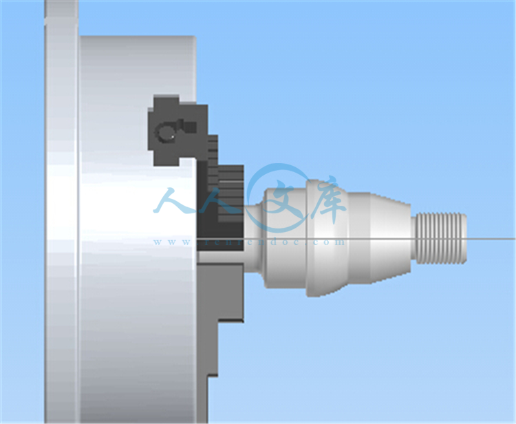
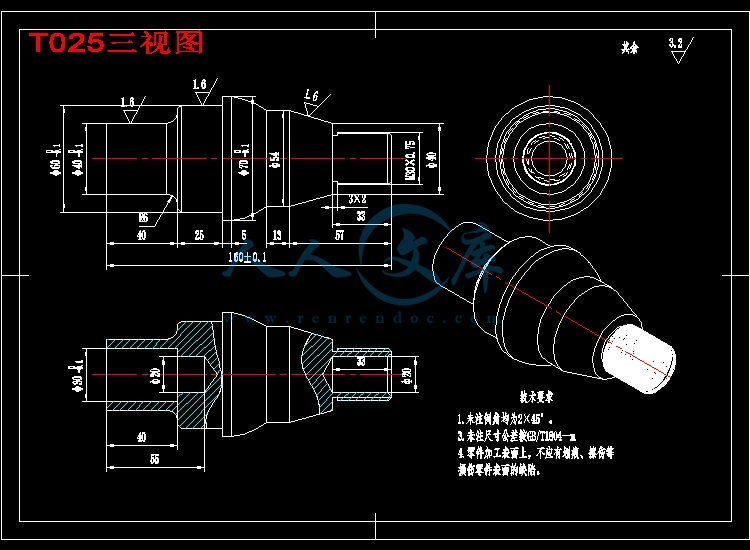
中凸轴零件的数控车削加工工艺及编程【带三维图】【优秀数控类课题】【带仿真】
【详情如下】CAD图纸+word设计说明书.doc[9200字,34页]【需要咨询购买全套设计请加QQ97666224】.bat
零件图.dwg
T025三视图.dwg
UG3D.prt
外文翻译=CNC数控技术=5000字符.doc
实习报告.doc
设计说明书.doc[9200字,34页]
摘要 随着科学技术的进步,现代机械产品日趋精密复杂,改型换代频繁,发展现代数控 机床是当前机械制造业技术改造、技术更新的必由之路。数控机床当中数控车床应用比 较广泛,该设计内容是对数控车床简单了解。
本文主要讨论典型轴类零件的数控车削加工工艺,通过对典型轴零件的分析完成该零件的数控车削加工工艺的编排、机床的选择、刀具的选择、切削用量的选择、程序的编制、加工仿真、实体建模等等;通过对具体的普通零件的车削加工,了解数控车床加工的基本特点、工艺分析与工艺设计方法;数控编程基础知识。 本毕业设计构思新颖,结构合理,图文并茂,针对性强,注重实际应用。
关键词 工艺分析 刀具选择 程序设计
目录
引言4
第一章数控加工基础5
1.1 数控机床简介5
1.2 数控车削加工指令简介6
1.2.1 F功能6
1.2.2 S功能6
1.2.3 T功能6
1.2.4 辅助功能字M7
1.2.5 准备功能字G7
第二章 典型车削零件的工艺分析8
2.1 零件图8
2.1.1 零件图的分析9
2.1.2 零件基准与加工定位基准9
2.2 机床的选择11
2.3 夹具的选择11
2.4 刀具的选择13
2.5 切削用量的选择14
2.5.1 主轴转速的确定14
2.5.2 进给速度的确定16
2.5.3 背吃刀量的确定17
2.6 走刀路线的确定17
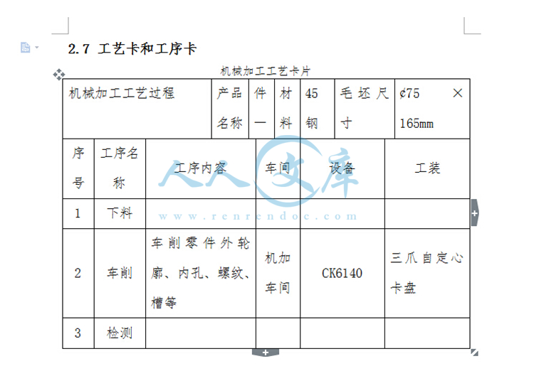
2.7 工艺卡和工序卡19
第三章 数控编程23
3.1 数控编程的定义23
3.2 数控编程的分类23
3.3 工件坐标系的确定23
3.4 数值的计算23
3.5 零件的加工程序清单23
3.5.1 加工左端轮廓程序24
3.5.2 加工右端轮廓程序26
3.6 数控加工仿真29
3.6.1 零件左端仿真结果29
3.6.2 零件右端仿真结果30
3.7 零件实体造型31
总结32
致谢33
参考文献34
引言
制造业是我国国民经济的支柱产业,其增加值约占我国国内生产总值的40%以上,而先进的制造技术是振兴制造业系统工程的重要组成部分。21世纪是科学技术突飞猛进、不断取得新突破的世纪,它是数控技术全面发展的时代。数控机床代表一个民族制造工业现代化的水平,随着现代化科学技术的迅速发展,制造技术和自动化水平的高低已成为衡量一个国家或地区经济发展水平的重要标志。
数控车床是目前使用最广泛的数控机床之一。数控车床主要用于加工轴类、盘类等回转体零件。通过数控加工程序的运行,可自动完成内外圆柱面、圆锥面、成形表面、螺纹和端面等工序的切削加工,并能进行车槽、钻孔、扩孔、铰孔等工作。车削中心可在一次装夹中完成更多的加工工序,提高加工精度和生产效率,特别适合于复杂形状回转类零件的加工。
本文主要讨论的就是作为制造业的组成部分数控车床。主要内容有关于数控车床的编程方法、编程的注意事项、加工工艺分析、刀具的选用、刀位轨迹计算。


- 内容简介:
-
外文资料翻译译文 CNC 技术 数控( NC)是可编程的自动化的一种形式。其加工设备由一系列的数字、字母和其他符号控制。这些数字、字母和符号被编成一定的格式,以便为一个特定的工步或者工作定义一个指令程序。当工作改变时,指令程序也随之改变。这种改变程序的能力使 NC 适应小、中批量生产。编写新的程序要比大批量调换生产设备容易的多。 1.NC 的基本组成部分 一个数控系统包括以三个组成部分:指令编程、机械控制单元、加工设备。 三者之间的关系是:程序导入控制单元,控制单元直接指导加工设备的动作。 指令程序是细化的一步步 的命令,它控制加工设备。在它的一般形式中,命令涉及到机床主轴和放置工件的工作台的相对位置。许多先进的指令包含有选择主轴速度,切削工具等功能。程序编在一个适当的媒介中,再导入到控制单元中。在几十年前最常用的媒介是一英尺宽的穿孔纸带。由于穿孔纸带的广泛应用, NC 也叫做“纸带控制”。现在磁带和软盘得到了广泛的应用。 加工设备的 NC 系统的第三个基本组成部分。它是有效工作的执行部分。在许多数控的例子中,加工设备包括工作台、主轴和驱动和控制它们的设备。 2.控制系统的种类 在 NC 中有两种基本控制类型:点到点和仿型定位。 在点到点系统中(也叫做点定位),机床的每一个轴都单独驱动。为了减少不加工时间,机床一最大的速度运动。但刀具达到定位点时开始减速。因此在一个加工过程中,比如钻削或冲压,加工过程和回程独立完成。在孔被钻出或冲出后,刀具撤回,移动到另一个地方,继续下一次加工。从一点到另一点的路径在一个放面十分重要:为提高效率,所需时间必须最小。点定位主要用于钻削、虫牙和立式洗削加工。 在仿型定位系统中(也被称为沿路径加工系统),定位和加工都沿着指定的路径,但速度不一样。因此刀具沿着指定的路径运动,速度和运动的同步精确控制十分重要 。仿型定位系统用于车床、磨床、焊接机械和加工中心中。 在几种基本方法之一的控制之下,刀具沿着路径发生微量的移动。在 NC 程序中,不同的刀具有不同的刀具补偿。 为使仿型数控加工中有光滑的路径,开发了许多补偿方式用以处理这些问题。他们包括:直线插补,圆弧插补,螺旋插补,抛物线插补,三次曲线插补。 直线插补是最基本的。当仿型加工路线是直线时用到它。两轴和三轴直线插补在实际nts运用中有一定的区别,但概念上是一致的。程序需要指定直线的起点和终点,并指定沿直线的进给速度。为了得到指定的沿直线的进给速度,插补要计算出两轴(三轴 )的每一轴的进给速度。 如果要创建一个圆弧路径,直线插补是不合适的。因为程序需要指定圆弧和它们各自的终点。圆弧插补已经发展了。它允许路径的程序包含圆弧,这个圆弧由以下参数定义:终点坐标、圆弧中心坐标、半径和沿圆弧加工的方向。创造出的刀具路径包含一系列的直线线段,但这些线段由插补模型计算,而不是程序本身。刀具沿着每一条线段一条接一条的移动,加工出光滑的圆弧路径。圆弧插补的限制是圆弧存在的平面必须在一个由 CNC 系统的二轴定义的平面内。 螺旋插补使两轴描述的圆弧插补和第三轴的直线运动结合了起来。它允许在在三维空间 里定义一个三维的路径。 抛物线和三次曲线插补利用一个高阶方程提供一个复杂的自由曲线。它们通常需要很大的计算量,因此不如直线和圆弧插补常用。它们用于自动化工业的模具制造中。这些设计中不能精确和方便的由直线和圆弧插补近似。 3.加工工具的选择和加工工艺规程的制定 加工工具的选择和加工工艺规程的制定是数控加工的一个重要的内容,它不仅影响到数控加工的效率,还直接影响到加工质量。 CAD/CAM 技术的发展,使数控加工能直接运用CAD 设计数据,特别是微机和数控模块,使设计工艺过程和编程的全过程都由计算机完成,而不需要输出 特定的技术文件。 如今,许多 CAD/CAM 软件包都提供自动编程功能,这些软件即时更新编程中遇到的问题,加工刀具的选择,加工方式的计划和加工规范的制定等等。编程人员只需建立先关的参数,就可以自动完成数控生产,还可以与数控模块通信。因此,在数控加工中,刀具的选择和加工规范的制定完全取决于机床的条件。与此同时也需要编程人员掌握刀具的选择和工艺规范的制定原则,因为编程须完全考虑数控加工的特征。 数控加工经常使用的刀具种类和特征 数控加工刀具必须适应高速性,高效性和自动高级特征,应该包括一般刀具和特殊用途的刀具。数控 刀具的划分有多种方法。许多刀具通过其结构划分成:( 1)整体式刀具( 2)装配式刀具。运用焊接或者机械加紧方式。机械加紧式又可以分为可转位和不可转位两种。按刀具的材料可分为高速钢( 1)高速钢刀具( 2)硬质合金刀具( 3)金刚石刀具( 4)其他材料刀具。如立方碳化硼刀具,陶瓷刀具等等。还有按切削工艺可分为( 1)成型刀具( 2)钻孔刀具。包括麻花钻、扩孔钻,忽刀等等( 3)镗刀( 4)铣刀等等。为了适应数控机床对刀具稳定性、易更换性等的要求,近几年装配式的可转位刀具得到了普遍的应用。占到整个数控机床刀具的 30%-40%,金 属的数量达到 80%-90%。 4.数控程序 一个数控程序包含一系列的能使数控机床正确加工的指令。 NC 程序由内置程序完成,nts在商品架上或者从外部资源购买。程序也可以手工或者计算机辅助编程。 程序包括指令和命令, G 指令定义刀具和工件间的相互运动。 P 指令定义主轴转速、进给速度、刀具等。 T 指令定义插补号和工作台或刀具的快、慢移动。 S 指令定义主轴转动、换刀和工件的进给等等。 ( 1)手工编程 手工编程首先计算刀具、工件和工作台的相互位置关系。它基于工程图和制造工艺和它们的顺序。然后准备好一个表,其中包括加工特定工序所 需的必要信息。例如:切削刀具、主轴转速、进给速度、切削深度、切削液、切削力、刀具或者工件的相对位置和运动。有了这些信息,程序部分就准备好了。通常输出程序的纸带要先准备好。 手工编程可以由懂得特定加工过程的专业人士来做,他可以理解、阅读和改变程序。因为他们熟悉机床刀具,一些有能力的,有技术的工程师通过一些编程训练就可以手工编程。然而,这项工作十分乏味、耗时。手工编程大多数情况下用于简单的点定位中。 ( 2)计算机辅助编程 计算机辅助编程有特殊的程序语言。它决定了工件的拐角、边缘、和表面上的相关点。程序语言是和 计算机交流的一种方式。编程人员用这种语言描述加工零件,而由计算机将零件程序转化为数控机床的执行指令。一些有多种特征和应用的语言都可以使用。第一种被运用的类似英语的语言叫做 ATP(自动编程工具),它在十九世纪五十年代末开发出来了。这种语言仍然在点定位和仿型定位中得到了广泛的应用。 计算机辅助编程与手工编程相比有如下优势:,符号语言的简单应用,减少了编程时间。程序可以存储大量的与加工过程有关的数据,例如:力、速度、进给量、刀具形状、刀具形状补偿、偏差等。减少了手工编程中的人为错误的可能性。简单的机械顺序或机床到 机床变化的能力。降低成本(编程只需很少时间)。 编程语言的应用不仅导致了高的质量,而且使机器指令有了飞速的发展。而且,模型可以移动到电脑终端,确保了程序功能是想要的。这种方法防止采用不必要的昂贵的机床来加工。 选择一个特定的 NC 程序语言主要取决于以下因素:制造设备个体专长水平,部件的复杂程度,可用的设备和电脑型号,编程中的时间和成本。 因为数控中数据的输入与工件材料和加工过程有关,程序必须由有机器加工相关方面知识的加工人员或者编程人员完成。在生产开始前,程序必须被验证,或者通过 CRT 屏幕观看加工过程的模型, 或者用不贵重的材料模拟加工,例如:铝、木材或者塑料。 5.加工中心 当前,许多技术更为先进的车床叫做加工中心。因为,它们除了完成常规的车削工作之外,还可以完成某些铣削、钻削工作。加工中心基本上可以认为是转塔车床和铣床的组合体。有时,制造厂商为了增加机床的多用性,还会增加一些其他的性能 。 6.数 字 控 制 先进制造技术中的一个最基本的概念是数字控制( NC)。在数控技术出现之前,所有的机床都是由人工操纵和控制的。在与人工控制的机床有关的很多局限性中,操作者的技nts能大概是最突出的问题。采用人工控制时,产品的质量直 接与操作者的技能有关。数字控制代表了从人工控制机床走出来的第一步。 数字控制意味着采用预先录制的,存储的符号指令,控制机床和其他制造系统。一个数控技师的工作不是去操纵机床,而是编写能够发出机床操纵指令的程序。对于一台数控机床,其上必须装有一个被称为阅读机的界面装置,用来接受和解译编程指令。 发展数控技术是为了克服人类操作者的局限性,而且它确实完成了这项工作。数字控制的机器比人工控制的机器的精度更高、生产的零件的一致性更好、生产的速度更快、而且长期的工艺装备成本更低。数控技术的发展导致制造工艺中的其他几项新发 明的产生:电火花加工技术,激光切削,电子束焊接。 数字控制还使得机床比它们采用人工操纵的前辈们的用途更为广泛。一台数控机床可以自动生产很多种类的零件,每个零件都可以有不同的和复杂的加工过程。数控可使生产厂家承担那些对于采用人工控制的机床和工艺来说,在经济上是不划算的产品的生产任务。 与许多先进技术一样,数控诞生于麻省理工学院的实验室中。数控这个概念是 20 世纪 50 年代初在美国空军的资助下提出来的。在其最初的阶段,数控机床可以经济和有效地进行直线切割。 然而,曲线轨迹成为机床加工的一个问题,在编程时应该采用一系 列的水平与竖直的台阶来生成曲线。构成台阶的每个线段越短,曲线就越光滑。台阶中的每个线段都必须经过计算。 在这个问题促使下,与 1959 年诞生了自动编程工具( APT)语言。这是一个专门适用于数控的编程语言,使用类似于英语的语句来定义零件的几何形状,描述切削刀具的形状和规定必要的运动。 APT 语言的研究和发展是在数控技术进一步发展过程中的一大进步。最初的数控系统与今天应用的数控系统是有很大的差别的。在那时的机床中,只有硬线逻辑电路。指令程序写在穿孔纸带上(它后来被塑料磁带所取代),采用带阅读机将写在纸带或磁带上的指 令给机器翻译出来。所有这些共同构成了机床数字控制方面的巨大的进步。然而,在数控发展的这个阶段中还存在着许多问题。 一个主要问题是穿孔纸带的易损坏性。在机械加工过程中,载有编程指令信息的纸带断裂和被撕坏是常见的事情。在机床上每加工一个零件,都需要将载有编程指令的纸带放入阅读机中重新运行一次。因此,这个问题变的很严重。如果需要制造 100 个某种零件,则应该将纸带分别通过阅读机 100 次。易损坏的纸带显然不能承受严酷的车间环境和这种重复使用。 这就导致了一种专门的塑料磁带的研制。在纸带上通过采用一系列的小孔来载有编程指令,而在塑料带上通过采用一系列的磁点来载有编程指令。塑料带的强度比纸带度要高很多,这就可以解决常见的撕坏和断裂问题。然而,它仍然存在着两个问题。 其中最重要的一个问题是,对输入带中的指令进行修改是非常困难的,或者是根本不可能的。即使对指令程序进行最微小的调整。也必须中断加工,制作一条新带。而且带通过阅读机的次数还必须与需要加工的零件的个数相同。幸运的是,计算机技术的实际应用很快解决了数控技术中与穿孔纸带和塑料带有关的问题。 nts在形成直接数字控制( DNC)这个概念后,可以不再采用纸带或塑料带作为编程指令的载体 ,这样就解决了与之有关的问题。在直接数字控制中,几台机床通过数据传输线路连接到一台主计算机上。操纵这些机床所需要的程序都存储在这台主计算机中。当需要时,通过数据传输线路提供给每台机床。直接数字控制是在穿孔纸带和塑料带基础上的一大进步。然而,它也有着与其他依赖于主计算机的技术一样的局限性。当主计算机出现故障时,由其控制的所有机床都将停止工作。这个问题促使了计算机数字控制技术的产生。 微处理器的发展为可编程逻辑控制器和微型计算机的发展做好了准备。这两种技术为计算机数控( CNC)的发展打下了基础。采用 CNC 技术后 ,每台机床上都有一个可编程逻辑控制器或者微机对其进行数字控制。这可以使得程序被输入和存储在每台机器内部。它还可以在机床以外编制程序,并且将其下载到每台机床中。计算机数控解决了主计算机发生故障所带来的问题,但是它产生了另一个被称为数据管理的问题。同一个程序可能要分别装入十个相互之间没有通信联系的微机中。这个问题正在解决之中,它是通过采用局部区域网络将各个微机连接起来,以利于更好地进行数据管理。 nts 外文原文 CNC TECHNOLOGY Numerical control (NC) is a form of programmable automation in which the processing equipment is controlled by means of numbers, letters, and other symbols. The numbers, letters, and symbols are coded in an appropriate format to define a program of instructions for a particular workpart or job. When the job changes, the program of instructions is changed. The capability to change the program is what makes NC suitable for low-and medium-volume production. It is much easier to write new programs than to make major alterations of the processing equipment. 1.BASIC COMPONENTS OF NC A numerical control system consists of the following three basic components:Program of instructions, Machine control unit, Processing equipment。 The general relationship among the three components is: the program is fed into the control unit, which directs the processing equipment accordingly. The program of instructions is the detailed step-by-step commands that direct the processing equipment. In its most common form, the commands refer to positions of a machine tool spindle with respect to the worktable on which the part is fixtured. More advanced instructions include selection of spindle speeds, cutting tool, and other function. The most common medium in use over the last several decades has been 1-in. -wide punched tape. Because of the widespread use of the punched tape, NC is sometimes called “tape control”. However, this is a misnomer in modern usage of numerical control. Coming into use more recently have been magnetic tape cassettes and floppy diskettes. The machine control unit (MCU) consists of the electronics and control hardware that read and interpret the program of instruction and convert it into mechanical actions of the machine tool or other processing equipment. The processing equipment is the third basic component of an NC system. It is the component that performs useful work. In the most common example of numerical control, one that performs machining operations, the processing equipment consists of the worktable and spindle as well as the motors and controls needed to drive them. nts2.Types Of Control Systems There are two basic types of control systems in numerical control: point-to-point and contouring. In the point-to-point system, also called positioning, each axis of the machine is driven separately by leadscrews and, depending on the type of operation, at different velocities. The machine moves initially at maximum velocity in order to reduce nonproductive time but decelerates as the tool reaches its numerically defined position. Thus in an potation such as drilling or punching, the positioning and cutting take place sequentially. After the hole is drilled or punched, the tool retracts, moves rapidly to another position, and repeats the operation. The path followed from one position to another is important in only one respect: The time required should be minimized for efficiency. Point-to-point systems are used mainly in drilling, punching, and straight milling operations. In the contouring system, also known as the continuous path system, positioning and cutting operations are both along controlled paths but at different velocities. Because the tool cuts as it travels along a prescribed path, accurate control and synchronization of velocities and movements are important. The contouring system is used on lathes, milling machines, grinders, welding machinery, and machining centers. Movement along the path, or interpolation, occurs incrementally, by one of several basic methods. In all interpolations, the path controlled is that of the center of rotation of the tool. Compensation for different tools, different diameter tools, or tool wear during machining, can be made in the NC program. There are a number of interpolation schemes that have been developed to deal with the various problems that are encountered in generating a smooth continuous path with a contouring-type NC system. They include:Linear interpolation, Circular interpolation, Helical interpolation, Parabolic interpolation, Cubic interpolation。 Each of these interpolation procedures permits the programmer (or operator) to generate machine instructions for linear or curvilinear paths, using a relatively few input parameters. The interpolation module in the MCU performs the calculations and directs the tool along the path. Linear interpolation is the most basic and is used when a straight-line path is to be generated in continuous-path NC. Two-axis and three-axis linear interpolation routines are sometimes distinguished in practice, but conceptually they are the same. The program is required to specify the beginning point and end point of the straight line, and the feed rate that is to be followed along the straight line. The interpolator computes the feed rates for each of the two (or three) axes in order to achieve the specified feed rate. ntsLinear interpolation for creating a circular path would be quite inappropriate because the programmer would be required to specify the line segments and their respective end points that are to be used to approximate the circle. Circular interpolation schemes have been developed that permit the programming of a path consisting of a circular arc by specifying the following parameters of the arc: the coordinates of its end points, the coordinates of its center, its radius, and the direction of the cutter along the arc. The tool path that is created consists of a series of straight-line segments, but the segments are calculated by the interpolation module rather than the programmer. The cutter is directed to move along each line segment one by one in order to generate the smooth circular path. A limitation of circular interpolation is that the plane in which the circular arc exists must be a plane defined by two axes of the NC system. Helical interpolation combines the circular interpolation scheme for two axes described above with linear movement of a third axis. This permits the definition of a helical path in three-dimensional space. Parabolic and cubic interpolation routines are used to provide approximations of free-form curves using higher-order equations. They generally require considerable computational power and are not as common as linear and circular interpolation. Their applications are concentrated in the automobile industry for fabricating dies for car body panels styled with free-form designs that cannot accurately and conveniently be approximated by combining linear and circular interpolations. 3.Programming For NC A program for numerical control consists of a sequence of directions that causes an NC machine to carry out a certain operation, machining being the most commonly used process. Programming for NC may be done by an internal programming department, on the shop floor, or purchased from an outside source. Also, programming may be done manually or with computer assistance. The program contains instructions and commands. Geometric instructions pertain to relative movements between the tool and the work piece. Processing instructions pertain to spindle speeds, feeds, tools, and so on. Travel instructions pertain to the type of interpolation and slow or rapid movements of the tool or worktable. Switching commands pertain to on/off position for coolant supplies, spindle rotation, direction of spindle rotation, tool changes, work piece feeding, clamping, and so on. (1) Manual Programming Manual part programming consists of first calculating dimensional relationships of the tool, work piece, and work table, based on the engineering drawings of the part, and manufacturing ntsoperations to be performed and their sequence. A program sheet is then prepared, which consists of the necessary information to carry out the operation, such as cutting tools, spindle speeds, feeds, depth of cut, cutting fluids, power, and tool or work piece ally a paper tape is first prepared for trying out and debugging the program. Depending on how often it is to be used, the tape may be made of more durable Mylar. Manual programming can be done by someone knowledgeable about the particular process and able to understand, read, and change part programs. Because they are familiar with machine tools and process capabilities, skilled machinists can do manual programming with some training in programming. However, the work is tedious, time consuming, and uneconomical-and is used mostly in simple point-to-point applications. (2) Computer-Aided Programming Computer-aided part programming involves special symbolic programming languages that determine the coordinate points of corners, edges, and surfaces of the part. Programming language is the means of communicating with the computer and involves the use of symbolic characters. The programmer describes the component to be processed in this language, and the computer converts it to commands for the NC machine. Several languages having various features and applications are commercially available. The first language that used English-like statements was developed in the late 1950s and is called APT (for Automatically Programmed Tools). This language, in its various expanded forms, is still the most widely used for both point-to-point and continuous-path programming. Computer-aided part programming has the following significant advantages over manual methods: Use of relatively easy to use symbolic language Reduced programming time. Programming is capable of accommodating a large amount of data concerning machine characteristics and process variables, such as power, speeds, feed, tool shape, compensation for tool shape changes, tool wear, deflections, and coolant use. Reduced possibility of human error, which can occur in manual programming Capability of simple changeover of machining sequence or from machine to machine. Lower cost because less time is required for programming. Selection of a particular NC programming language depends on the following factors: a) Level of expertise of the personnel in the manufacturing facility. b) Complexity of the part. c) Type of equipment and computers available. d) Time and costs involved in programming. Because numerical control involves the insertion of data concerning work piece materials and processing ntsparameters, programming must be done by operators or programmers who are knowledgeable about the relevant aspects of the manufacturing processes being used. Before production begins, programs should be verified, either by viewing a simulation of the process on a CRT screen or by making the part from an inexpensive material, such as aluminum, wood, or plastic, rather than the material specified for the finished part. 4.Cutting tool choice and cutting specifications determination in CNC processing The cutting tool choice and the cutting specifications determination is in the numerical control processing craft important content, it not only influence numerical control engine bed processing efficiency, moreover affects the processing quality directly. CAD/The CAM technology development, enables in the numerical control processing to become directly using the CAD design data possibly, specially the microcomputer and the numerical control engine bed joint, causes the design, the craft plan and the programming entire process completes completely on the computer, does not need to output the special technological document generally. Now, many CAD/The CAM software package all provides the automatic programming function, these software are generally prompt the craft plan in the programming contact surface the related question, for instance, cutting tool choice, processing way plan, cutting specifications hypothesis and so on, programmers so long as have established the related parameter, may automatically produce completes the processing the NC procedure and the transmission to the numerical control engine bed. Therefore, in the numerical control processing cutting tool choice and the cutting specifications determination is completes under the man-machine interactive condition, this forms the sharp contrast with the ordinary engine bed processing, at the same time also requests the programmers to have to grasp the cutting tool choice and the cutting specifications determination basic principle, when programming full consideration numerical control processing characteristic. This article the cutting tool choice and the cutting specifications which must face to the numerical control programming in determined the question has carried on the discussion, has produced certain principles and the suggestion, and to the question which should pay attention has carried on the discussion. First, numerical control processing commonly
- 温馨提示:
1: 本站所有资源如无特殊说明,都需要本地电脑安装OFFICE2007和PDF阅读器。图纸软件为CAD,CAXA,PROE,UG,SolidWorks等.压缩文件请下载最新的WinRAR软件解压。
2: 本站的文档不包含任何第三方提供的附件图纸等,如果需要附件,请联系上传者。文件的所有权益归上传用户所有。
3.本站RAR压缩包中若带图纸,网页内容里面会有图纸预览,若没有图纸预览就没有图纸。
4. 未经权益所有人同意不得将文件中的内容挪作商业或盈利用途。
5. 人人文库网仅提供信息存储空间,仅对用户上传内容的表现方式做保护处理,对用户上传分享的文档内容本身不做任何修改或编辑,并不能对任何下载内容负责。
6. 下载文件中如有侵权或不适当内容,请与我们联系,我们立即纠正。
7. 本站不保证下载资源的准确性、安全性和完整性, 同时也不承担用户因使用这些下载资源对自己和他人造成任何形式的伤害或损失。

人人文库网所有资源均是用户自行上传分享,仅供网友学习交流,未经上传用户书面授权,请勿作他用。
 川公网安备: 51019002004831号