【温馨提示】 购买原稿文件请充值后自助下载。
以下预览截图到的都有源文件,图纸是CAD,文档是WORD,下载后即可获得。
预览截图请勿抄袭,原稿文件完整清晰,无水印,可编辑。
有疑问可以咨询QQ:414951605或1304139763
摘 要
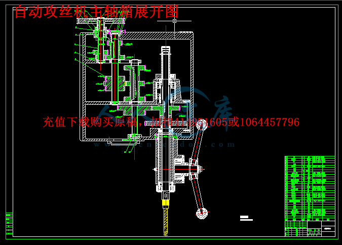
本文主要进行的是自动攻丝机设计,该自动攻丝机在普通的小台式钻床机床上进行设计,设计机床得主传动变速系统时首先利用传动系统设计方法求出理想解和多个合理解。根据数控机床主传动系统及主轴功率与转矩特性要求,分析了机电关联分级调速主传动系统的设计原理和方法。从主传动系统结构网入手,确定最佳机床主轴功率与转矩特性匹配方案,计算和校核相关运动参数和动力参数。本说明书着重研究机床主传动系统的设计步骤和设计方法,根据已确定的运动参数以变速箱展开图的总中心距最小为目标,拟定变速系统的变速方案,以获得最优方案以及较高的设计效率。在机床主传动系统中,为减少齿轮数目,简化结构,缩短轴向尺寸,用齿轮齿数的设计方法是试算,凑算法,计算麻烦且不易找出合理的设计方案。本文通过对主传动系统中三联滑移齿轮传动特点的分析与研究,绘制零件工作图与主轴箱展开图及剖视图。
关键词:分级变速;传动系统设计;传动副;结构网;结构式;齿轮模数;传动比
Abstract
First, in order to obtain the ideal and more understanding of the design method of transmission system design of machine tool transmission system when the winner. According to the requirements of the main drive system of CNC machine tool and spindle power and torque characteristics, analysis of the design principle and method of mechanical and electrical connection and speed of main transmission system. Starting from the main drive system structure network, determine the optimum matching scheme of machine tool spindle power and torque characteristics, the calculation and verification of relevant motion parameters and dynamic parameters. Design steps and design method of this specification focuses on the main drive system of machine tool, according to the motion parameters have been determined by transmission center distance of expansion graph of the minimum as the goal, formulate transmission scheme transmission system, in order to obtain the optimal scheme and high design efficiency. In the main drive system of machine tool, in order to reduce the number of gears, simplify the structure, reduce the axial size, design method of the number of gear teeth is trial, join algorithm, design calculation of trouble and is not easy to find a reasonable. Through the research and analysis of the main drive system of triple slide gear characteristics, draw the part drawing and the spindle box expansion plan and section view.
Key Words: classification of transmission; the transmission system; design; transmission; network structure; structure type; the module of gear; transmission ratio
目 录
摘 要II
AbstractIII
1 绪论1
1.1 钻床简介1
1.2 钻床的发展及趋势1
1.3 自动攻丝机介绍2
1.4 本课题设计内容及要求3
2 自动攻丝机总体方案设计4
2.1 自动攻丝机的动力选择4
2.2 自动攻丝机的驱动方式4
2.3 自动攻丝机的动力性能比较5
2.4 自动攻丝机动力的计算与选择6
3 自动攻丝机设计8
3.1 运动参数及转速图的确定8
3.1.1转速范围8
3.1.2转速数列8
3.1.3确定结构式9
3.1.4确定结构网9
3.1.5绘制转速图和传动系统图10
3.2 确定各变速组此论传动副齿数10
4 自动攻丝机动力计算12
4.1 带传动设计12
4.2 计算转速的计算13
4.3 齿轮模数计算及验算14
4.4 常用材料及热处理14
4.5 传动轴最小轴径的初定19
4.6 主轴合理跨距的计算20
5 主要零部件的选择22
5.1 轴承的选择22
5.2 键的规格22
5.3 变速操纵机构的选择22
6 校核23
6.1 刚度校核23
6.2 轴承寿命校核24
7 结构设计及说明26
7.1 结构设计的内容、技术要求和方案26
7.2 展开图及其布置26
结 论27
参考文献28
致 谢29
1 绪论
1.1 钻床简介
目前将机床分为12大类:车床、钻床、镗床、磨床、齿轮加工机床、螺纹加工机床、铣床、刨插床、拉床、特种加工机床、锯床及其他机床。在每一类机床中,又可以按照工艺范围、步型型式和结构等等,可以分为若干组,每一组又可以分为若干系列。如钻床又包括:坐标镗钻床、深孔钻床、摇臂钻床、台式钻床、立式钻床、卧式钻床、中心孔钻床及其他钻床。在上述的基本分类方法的基础上,还可以根据机床的其他特征进一步进行分类。同类型机床按照应用范围(通用性程度),可以分为通用机床(或者称万能机床)、专门化机床和专用机床三大类。其中通用机床是可以加工多种工件,完成多种多样工序的加工范围较广的机床,如卧式车床、摇臂钻床等等。
摇臂钻床主要由立柱,摇臂,主轴箱,和底座等部分组成。主轴箱装在摇臂上,可沿立柱上下移动,以适应加工不同高度工件的要求。此外,摇臂还可以随外立柱在360°范围回转,因此主轴很容易调整到所需要的加工位置。为了使主轴在加工时保持确定的位置,摇臂钻床还具有内立柱,摇臂及主轴箱的夹紧机构,当主轴的位置调整确定后,可以快速将它们夹紧。 摇臂钻床的其他变形如万向摇臂钻床摇臂和主轴箱可以回转或倾斜,使主轴可在空间任意方向都可以进行钻削,适用于重型机器,机车车辆,船舶和锅炉等制造业中加工大型工件。车式摇臂钻床的底座有车轮,可以在轨道上移动,适用于桥梁和机床等行业窄长形工件的孔加工。









 川公网安备: 51019002004831号