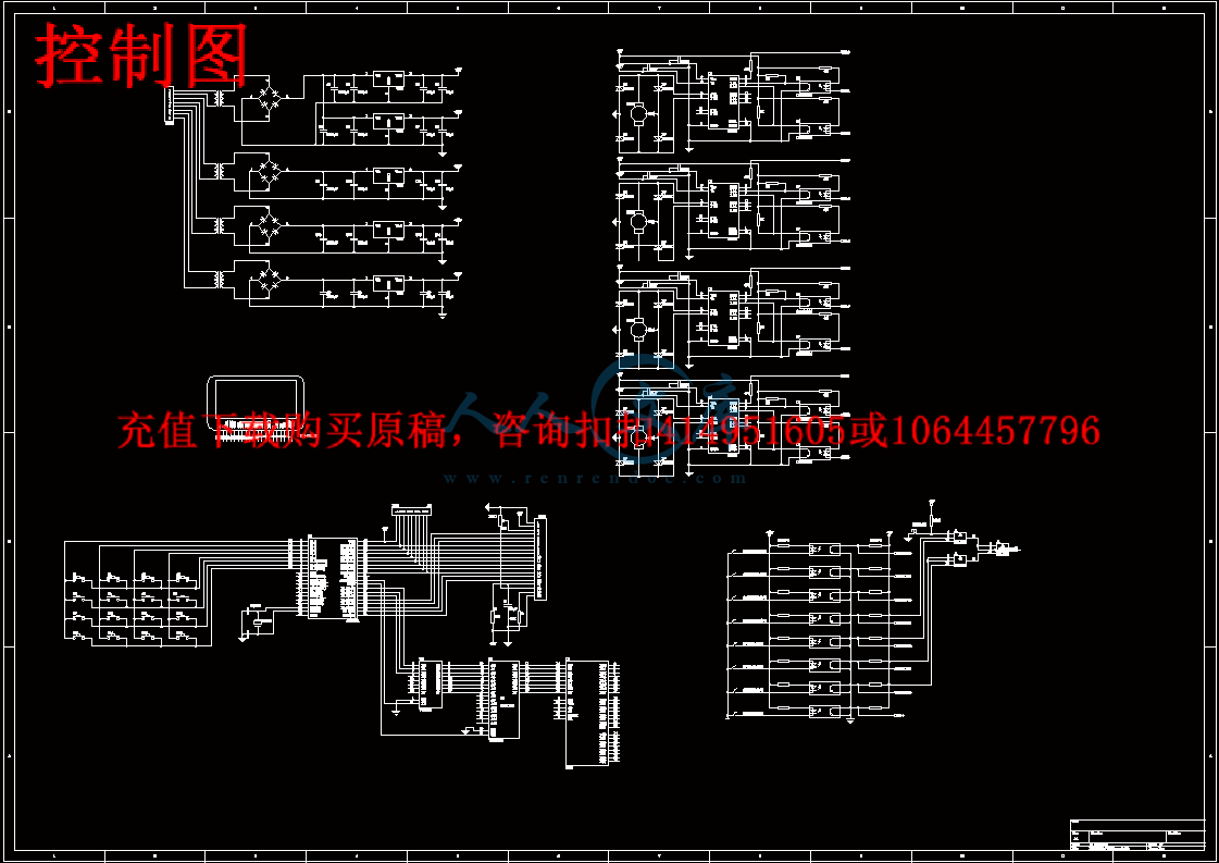
控制.pdf

多功能医用护理床的结构设计及优化-病床医疗床调理用【三维SW】【全套CAD图纸+毕业论文】【原创资料】

收藏

资源目录
跳过导航链接。
多功能医用护理床的结构设计及优化【优秀】【带SW三维】【全套CAD图纸+毕业论文】【原创资料】.rar
控制.pdf---(点击预览)
开题报告.doc---(点击预览)
外文.doc---(点击预览)
中文.doc---(点击预览)
1-多功能医用护理床的结构设计及优化.doc---(点击预览)
solidworks建模-27个三维图
上中板.SLDPRT
上侧板.SLDPRT
上侧板2.SLDPRT
下中板.SLDPRT
下侧板.SLDPRT
下侧板2.SLDPRT
下侧板3.SLDPRT
中下中板.SLDPRT
中下侧板.SLDPRT
中下侧板2.SLDPRT
中侧板.SLDPRT
中板.SLDPRT
侧翻(右边).SLDPRT
侧翻(左边).SLDPRT
床两侧.SLDPRT
床体.SLDPRT
床头尾.SLDPRT
抬背.SLDPRT
曲腿.SLDPRT
曲腿2.SLDPRT
直线驱动.SLDPRT
装配.SLDASM
驱动连杆.SLDPRT
驱动连杆300.SLDPRT
驱动连杆340.SLDPRT
驱动连杆400.SLDPRT
驱动连杆500.SLDPRT
外文翻译
A0总装配.DWG
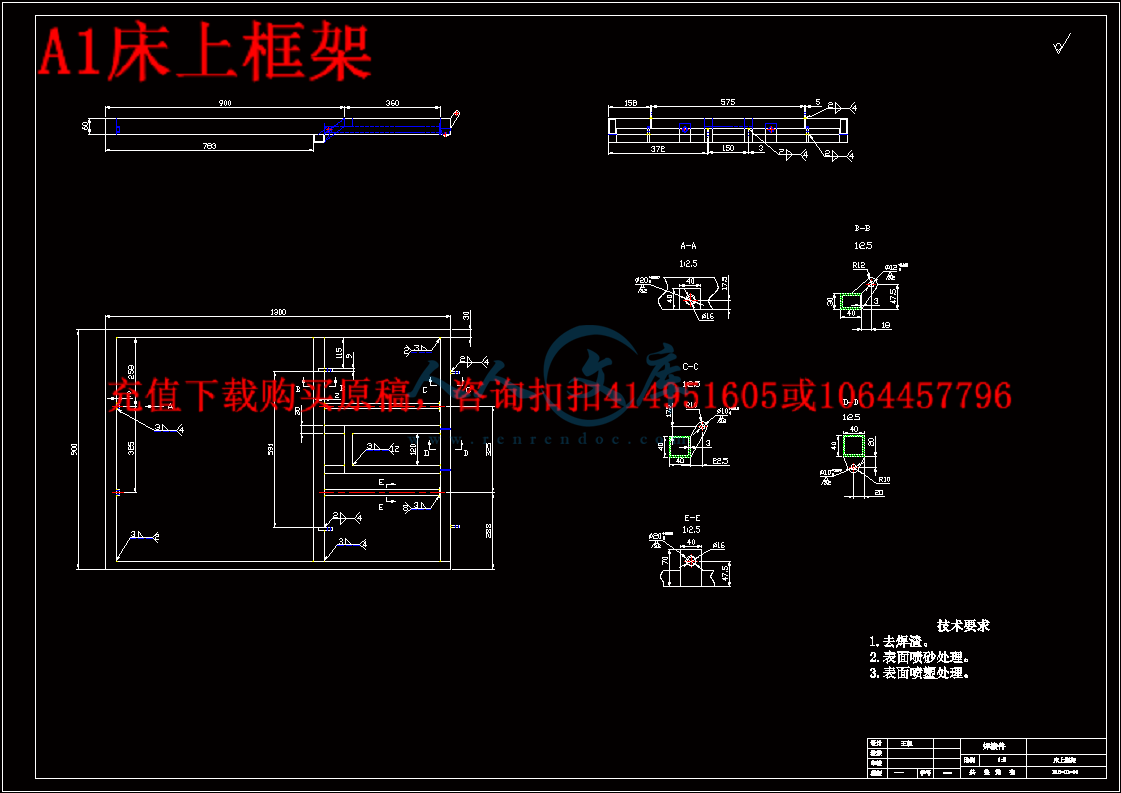
A1床上框架.DWG
A1床下框架.DWG
A2侧翻(左边).DWG
A3抬背.DWG
控制图.dwg
压缩包内文档预览:
预览图
编号:462389    类型:共享资源    大小:10.56MB    格式:RAR    上传时间:2015-07-29 上传人:好资料QQ****51605 IP属地:江苏
50
积分
关 键 词:
多功能 医用 护理 结构设计 优化 优秀 优良 sw 三维 全套 cad 图纸 毕业论文 原创 资料
资源描述:

【温馨提示】 购买原稿文件请充值后自助下载。

以下预览截图到的都有源文件,图纸是CAD,文档是WORD,下载后即可获得。


预览截图请勿抄袭,原稿文件完整清晰,无水印,可编辑

有疑问可以咨询QQ:414951605或1304139763

摘   要

多功能医用护理床是一种针对危重病人和瘫痪病人的特殊需要而设计的,能随意调节床的背部和脚部的角度。即使不能自理者,护理人员也可通过床边的控制器进行操作,减少照顾病、残患者的劳动强度。本文针对上述情况,提出了一种新型的多功能医用护理床,采用三维数字化设计软件soliderworks对其进行建模和装配,然后导出到CAD进行修改。利用机械分析软件ADAMS对其进行运动学及动力学分析,研究了床板在各种运动状况下的角加速度对患者舒适度的影响及线性推杆在各姿态下的受力状况,并利用ADAMS提供的优化功能对其分别进行了运动学和动力学优化;以角加速度最大值的最小化作为优化目标函数进行运动学优化,以线性推杆受力的最大值最小化作为动力学优化目标函数,得到满足设计要求的机构参数。采用力学理论分别对多功能医用护理床的主要零件进行力学计算,保证了机构运动的安全性及稳定性。控制系统采用单片机控制,通过单片机控制,实现各个机构的运动,安装传感器来控制机构所转过的角度。利用单片机为主的控制系统,达到控制要求。


关键词:多功能医用护理床,干涉检验,运动学优化,动力学优化,控制系统


ABSTRACT

Multifunction Nursing-bed is designed for those critically ill patients and the special needs of paralyzed patients designed bed is able to adjust the angle of the back and feet. Even if we can not take care of themselves, the nursing staff can also be operated bedside controller to reduce the care of sick and disabled patients with the labor intensity. In this paper, the above situation, a new type of multi-functional medical care beds, the use of digital three-dimensional design software for modeling and soliderworks its assembly, then export to CAD and correct it. the mechanical analysis software ADAMS kinematics and dynamics of its analysis, research of the bed board in the under a wide variety of sports on the angular acceleration of the impact of patient comfort and linear putter in the posture of the force, and provided the use of optimization ADAMS conducted its kinematic and dynamic optimization; to angular acceleration The minimum value of objective function as for kinematic optimization, linear putting maximum stress as a dynamic optimization to minimize the objective function. Have to meet the design requirements of the body parameters. Finite calibration methods of mechanics of materials, respectively, of multi-bed medical care for the mechanical parts of the main check to ensure the safety of the movement and stability. Control system adopts microcomputer control, through MCU control, to achieve the movement of various agencies, to install sensors to control the body turn angle. Use of microcomputer-based control system to control demand.


Key words: Multifunction Nursing-bed, interfere check, kinematics optimization, dynamics optimization, control system


目录

1 绪论1

1.1 课题的目的及意义1

1.2 国内外研究状况及发展趋势1

1.3 本文主要研究内容6

1.4 本章小结6

2 护理床结构的整体方案7

2.1 护理要求7

2.2 护理床的总体方案构思7

2.3 本章小结9

3 护理床的结构设计10

3.1 引言10

3.2 侧翻机构10

3.3 抬背机构11

3.4 曲腿机构13

3.5护理床的三维建模14

3.6 本章小结16

4 护理床运动学优化17

4.1 引言17

4.2侧翻机构的运动学分析17

4.3抬背机构的运动学分析23

4.4曲腿机构的运动学分析26

4.5本章小结29

5 护理床动力学优化30

5.1引言30

5.2侧翻机构动力学分析30

5.3抬背机构动力学分析32

5.4曲腿机构动力学分析34

5.5本章小结36

6 护理床的力学分析37

6.1 引言37

6.2 力学计算37

6.3 本章小结40

7 护理床控制系统设计41

7.1 引言41

7.2 直流电机控制原理41

7.3 控制系统方案41

7.4 控制系统的硬件设计43

7.5 控制系统的软件设计48

7.6 本章小结52

8 结论53

8.1 课题结论53

8.2课题展望53

参考文献54

致谢56


1 绪论

1.1 课题的目的及意义

多功能医用护理床是针对生活不能自理的病人、危重病人和瘫痪病人的特殊需要而设计的,能随意调节床的背部和脚部的角度。即使不能自理者,护理人员也可通过床边的控制器进行操作,减少照顾病、残患者的劳动强度。课题根据国家和上海市中长期发展纲要确定的研究方向和企业的具体需要,设计一种用于医院重症病人用的多功能床,解决病人身体和生理方面的需要(抬背、翻身等),也减轻护理人员的劳动强度。针对市场需求开发设计一种结构简单、工作可靠、使用方便的多功能护理床并进行动态仿真,对于产品的产业化具有重要的意义。


内容简介:
dell d e l l 穑 ?0b $7 鱝 鄕 /b? 坹 /b? (z/b? 纙/bz nts外文 资料 翻译 1 护理床动力学优化 5.1 引言 动力学是理论力学的一个分支学科,它主要研究作用于物体的力与物体运动的关系。动力学的研究对象是运动速度远小于光速的宏观物体。动力学是物理学和天文学的基础,也是许多工程学科的基础。 动力学以牛顿第二定律为核心,这个定律指出了力、加速度、质量三者间的关系。牛顿首先引入了质量的概念,而把它和物体的重力区分开来,说明物体的重力只是地球对物体的引力 。 多功能医用护理床的运动学分析是 基于 ADAMS 建立于在运动学分析的基础之上的,根据先前的运动学分析,以运动学分析结果作为动力学分析的初始值,综 合考虑线性推杆的推、拉力的限制以及机架各支点的受力状况,主要对线性推杆的受力状况及各床架支点的受力状况进行动力学分析。 5.2 侧翻机构动力学分析 5.2.1为机构添加外力 侧翻机构在运行的过程中,会有以下几个方面对机构运动产生影响。它们是机构自身质量,患者体重以及各个运动副之间的摩擦力。由于摩擦力很小,在此忽略不计,只考虑机构的重量及患者的体重。 通过 solidworks 软件对虚拟样机进行质量测量,测得背板质量为 20kg,通过设计手册查得我国身高 1.85m 的成年人平均体重为 83kg 左右。为了真实的模拟虚拟样 机的性能,本文采用背板质量为 20kg,人体背部重量为 50kg。对机构添加力之后,运行一次动力学仿真。测量各个点的受力以及电机的受力。仿真时间为 25s,步数为 500 步。 添加力测量,测得的各点受力曲线如图 5-1 所示。 图 5-1 各点受力曲线 nts外文 资料 翻译 2 5-2 MARKER_5 点优化前后受力曲线 5-3 MARKER_1 点优化前后受力曲线 5-4 MARKER_21 点优化前后受力曲线 5-5 各参数下的翻转角度值 5.2.2侧翻机构动力学优化仿真 从图 5-1 中,得知 MAKER_5 点的受力最大,机构的受力优化就从MARKER_5 着入。首先,测试各个设计变量对 MARKER_5 的受力变化的敏感度。运行一次动力学仿真,时间为 25s,步数为 500 步,线性推杆移动速度为5.5mm/s,背 板质心处加力 500N,背板自重 20kg。运行优化设计,优化的目标为将 MARLKER_5 点的受力的最大值进行最小化,仿真后优化数据如下: Model Name : model_1 Date Run : 2009-04-14 17:13:51 Objectives O1) Maximum of MARKER_5_MEA_1 Units : newton Initial Value: 1444.34 Final Value : 1130.2 (-21.7%) Iter. O1 DV_1 DV_2 DV_8 0 1444.3 150.00 295.00 136.30 1 1133.7 165.00 265.50 135.83 2 1130.2 165.00 265.50 134.94 3 1130.2 165.00 265.50 134.94 从图 5-2 至 5-4 中,可以发现经过动力学优化之后,各支点受力均有明显的改善,其中图 5-2 中 MARKER_5 点受力从 1443N 减至 1133N,从图 5-5 中,背板的转动角度在角度约束的范围之内。 nts外文 资料 翻译 3 5.2.3样机的实际结构 通过以上的分析,在实际设计中,各关键点的坐标取值为如表 5-1 所示 表 5-1 各关键点实际取值 DV_L1/mm DV_L2/mm DV_L4/mm DV_L7/mm DV_L8/mm 初始值 250 245 330 400 370 优化值 265 215 346.1 390.28 359.94 此时,样机的背板转动角加速度最小且各支点的受力也达到了最小化、满足了机构的设计要求。动力学优化前后机构构件尺寸表如表 5-2 所示: 表 5-2 优化前后杆件尺寸对比 A、 B 水平距离 /mm A、 B 竖直距离 /mm BD/mm 初始值 50 65 98.4 优化值 35 19 118 5.3 抬背机构动力学分析 5.3.1为机构添加力 为了较为真实的模拟人体的质量,以及考虑背板的推、拉力的限制,在抬背机构的背部添加竖直向下的均布力,大小为 400N,在臀部床板添加 400N 的力,运行一次动力学优化仿真。 5.3.2抬背机构动力学优化仿真 为了进一步研究线性推杆的受力状况,以及机架上各支点的受力状况,使得机构工作得更安全及更可靠,以抬背机构运动学优化数据为动力学优化的初始数据,优化目标函数为抬背过程中线性推杆受力的最大值最小化,进行动力学优化仿真,已得到满足机构设计要求的最优化参数。通过设计研究对各个设计变量进行敏感度测试。根据设计研究对各设计变量的测试,得到的数据报表如下: Trial O1 DV_1 Sensitivity 1 1914.3 369.00 10.740 2 2134.5 389.50 -0.021580 3 1913.4 410.00 -2.5693 4 2029.1 430.50 -0.019588 5 1912.6 451.00 -5.6838 Trial O1 DV_2 Sensitivity 1 1913.3 -18.000 0.0037970 2 1913.3 -27.000 -0.0031447 3 1913.4 -36.000 -11.532 nts外文 资料 翻译 4 4 2120.9 -45.000 -0.0029932 5 1913.5 -54.000 23.048 Trial O1 DV_3 Sensitivity 1 1925.6 90.000 22.755 2 2039.4 95.000 -1.2229 3 1913.4 100.00 -12.825 4 1911.2 105.00 -0.42287 5 1909.2 110.00 -0.39627 Trial O1 DV_4 Sensitivity 1 1912.8 -50.800 -0.079290 2 1913.3 -57.150 -0.044021 3 1913.4 -63.500 -0.042952 4 1913.9 -69.850 -0.069998 5 1914.3 -76.200 -0.062845 Trial O1 DV_5 Sensitivity 1 1913.5 3.9200 0.011536 2 1913.4 0.00000 0.0081747 3 1913.4 -3.9200 -0.012181 4 1913.5 -7.8400 -3.5109 5 1940.9 -11.760 -6.9926 Trial O1 DV_6 Sensitivity 1 2163.3 -111.15 40.476 2 1913.4 -117.32 20.238 3 1913.4 -123.50 -15.895 4 2109.7 -129.68 -0.0067767 5 1913.5 -135.85 31.777 Trial O1 DV_7 Sensitivity 1 1985.6 306.74 -4.2359 2 1913.4 323.78 -2.1180 3 1913.4 340.82 6.3905 4 2131.2 357.86 0.0011642 5 1913.4 374.90 -12.779 Trial O1 DV_8 Sensitivity 1 2163.3 -111.15 40.476 2 1913.4 -117.32 20.238 nts外文 资料 翻译 5 3 1913.4 -123.50 -15.895 4 2109.7 -129.68 -0.0067767 5 1913.5 -135.85 31.777 通过设计研究,观察计算结果,可以发现实际变量 DV_3、 DV_4、 DV_6、DV_8 的敏感度最大,所以在优化设计的时候着重考虑上述几个设计变量,对它们进行优化设计,以期望得到满足设计要求的机构最优化参数。 5.3.3样机的实际结构 通过以上的分析,在实际设计中,各关键点的坐标取值为如表 5-3 所示 表 5-3 各关键点实际取值 DV_2/mm DV_5/mm DV_6/mm DV_8/mm 初始值 390 458 330 275 优化值 381 452.603 32317 278.8 优化前后杆件尺寸变化如 表 5-4 所示。 表 5-4 优化前后杆件尺寸变化表 A、 C 竖直距离/mm BC /mm CD /mm DE/mm 初始值 60 236 256 667 优化值 62 228 248 659 图 5-6 抬背机构动力学优化前后电机受力曲线 观察图 5-6 可以得知在机构动力学仿真之后,机构表现出了良好的动力学性能,机构的受力状况得到了有效的改善,达到了预期的效果,即电机受力的最大值最小化。 5.4 曲腿机构动力学分析 为了真实的模拟曲腿机构在运行过程中的受力性能,以及线性推杆的受力状况,所以对曲腿机构在运 动学仿真的基础之上进行一次动力学仿真,为了得到较为真实的机构运行状况,并进行优化仿真,得到理想机构设计参数。 nts外文 资料 翻译 6 5.4.1为机构添加外力 综合考虑人体的自身重量以及床板的重量,在小腿板的质心处及脚板的质心处各添加竖直向下的力,大小为 500N。 5.4.2曲腿机构动力学仿真 以运动学优化的数据作为动力学优化的初始数据,进行动力学优化,优化的目标函数为电机受力最大值的最小化。首先,对各个设计变量进行设计研究,设计研究的报表如下: Trial O1 DV_1 Sensitivity 1 4229.0 270.00 10.633 2 4548.0 300.00 10.659 3 4868.5 330.00 10.686 Trial O1 DV_2 Sensitivity 1 4435.8 -56.700 -17.645 2 4519.2 -61.425 -18.141 3 4607.2 -66.150 -18.637 Trial O1 DV_3 Sensitivity 1 4833.0 156.75 -32.756 2 4427.7 169.12 -28.017 3 4139.6 181.50 -23.278 Trial O1 DV_4 Sensitivity 1 3850.1 -243.00 -25.573 2 4367.9 -263.25 -26.353 3 4917.4 -283.50 -27.134 Trial O1 DV_5 Sensitivity 1 4792.4 -81.498 55.604 2 4434.7 -87.932 51.809 3 4125.8 -94.366 48.013 Trial O1 DV_6 Sensitivity 1 4541.0 -597.60 -0.10561 2 4548.0 -664.00 -0.098506 3 4554.0 -730.40 -0.091406 根据上述的设计研究的结果对 DV_1、 DV_2、 DV_3、 DV_4、 DV_5、 DV_7、DV_9 七 变量,作为优化设计时的设计变量,进行动力学优化仿真。 nts外文 资料 翻译 7 图 5-7 曲腿机构动力学优化前后电机受力曲线图 观察图 5-7 可以得知,经过动力学优化后的电机受力的最大值由原来的4550N 减小为优化后的 2850N,电机的受力大大的减小,从而保证了机构运行的安全性及运行的稳定性。 5.4.3 样机的实际结构 通过以上的分析,在优化设计时选取上述设计变量作为优化设计时的设计变量,进行动力学优化,经过动力学优化之后,各关 键点的坐标取值为如表 5.5 所示 表 5-5 各关键点实际取值 DV_1/mm DV_2/mm DV_3/mm DV_4/mm DV_5/mm 初始值 300 -63 165 -270 -85.788 优化值 270 -56.7 181.5 -243 -94.36 此时,样机的线性推杆的受力最小且各支点的受力也达到了最小化、满足了机构的设计要求。优化前后机构杆件尺寸变化见表 5-6。 表 5-6 优化前后构件尺寸变化表 AB/mm BC/mm CD/mm DE/mm BE/mm 初始值 380 144.6 85 207.5 185.6 优化值 350 136.7 83.6 209.35 192.8 5.5 本章小结 本章在运动学分析的基础之上的,利用运动学分析的数据作为动力学分析的初始数据,对机构进行动力学分析;在满足机构运动学要求的基础上改善机构的动力学性能及机架的受力性能。使得样机的运动性能及受力性能达到最好,满足人体工学以及机构在工作过程中的稳定性及安全性。本章是进行样机物理设计的依据。 nts外文 资料 翻译 8 6 护理床的力学分析 6.1 引言 多 功能医用护理床在满足运动学及动力学性能要求的基础上,需要对其中的一些主 要零件进行强度校核,以便在设计的时候合理的选材,在保证多功能医用护理床安全性和稳定型以及尽可能的降低生产成本。 6.2 力学计算 护理床各主要部件及连杆材料均选用 Q235A 钢 6.2.1床底架杆校核 考虑到由于多功能医用护理床内的机构角度,不可避免的会使床的质量增加。由于整床的重量将全部压在床底架长杆上,所以底架长杆将会是受力最大的杆件,根据设计尺寸,底架长杆的长度为 1440mm,床底架长杆上有两个支撑点,假设床身的质量为 400kg,人体的质量为 150kg,总重为 550kg。具体计算如 下所示: 图 6-1 床底架受力示意图 根据 solidworks 的称重功能,测得床的质量为 365kg, 假设 床身的质量为400kg,人体的质量为 150kg,总重为 550kg。所以 F2=F3=2750N,ADl=1440mm,BCl=1020mm, CDl=70mm。 根据力矩平衡公式: F1ADl=F2BDl+F3CDl得: F1= 2 7 5 0 1 0 9 0 2 7 5 0 7 01440 =2215.3N F =F1+F4=F2+F3 得 F4=3284.7N nts外文 资料 翻译 9 通过上述已知条件,计算杆各段所受的剪力及弯矩: 以 A 为原点,在 AB 端内: 剪力 F=F1=2215.3N,方向向下 弯矩 M=F1 x 得: M=0775.355N M,方向为逆时针方向 在 BC 段内: 剪力 F=F2-F1=534.7N,方 向向上 弯矩 M=F1 x-F2( x-0.35) 得: M=229.9775.355N M,方向为逆时针方向 在 CD 段内: 剪力 F=F4=3284.7N,方向向上 弯矩 M=F4 x 得: M=0229.9N M,方向为逆时针方向 所以,根据计算分析,得出的结果为 B 点的受力最大且弯矩也最大,所以 B点所在在截面为危险截面。计算后的剪力图及弯矩图如图 6-2 所示。 图 6-2 床底架剪力及弯矩图 根据剪力及弯矩图说明了 床底架杆在整体上的受力并没有发生突变 , 同时也不存在在某段的力值特别大的现象,所以从整体上而言 , 床框架的力学性能良好,受力情况满足了机构的设计要求 。 6.2.2 抬背 杆校核 多功能医用护理床在抬背的时候,其抬背摆杆将是受力较大的杆件,由于人的背部质量较大,所以其将会时比较危险的杆件,对其的力学计算如下。 nts外文 资料 翻译 10 图 6-3 抬背杆受力示意图 按照人体的质量及床板的质量均分,则圆整后的数据为 F1=500N,方向向上。 F3x=950N, F3y=2039N,ACl=830mm,ABl=680mm, BDl=54mm。 F2x=F3x=950N, F2y=F1+F3y=500+2039=2539N 在 AB 段 剪力 F=F1=500N,方向向上 弯矩 M=F x,得: M=0340N M,方向为顺时针方向 在 BC 段 剪力 F= F3y=2039N,方向向下 弯矩 M=F2y( x-0.68) -F1 x (0.68 x 0.734) 得: M=229.9340N M,方向逆时针方向 M= F2y( x-0.68) +F2x 0.7343x -F1 x ( 0.734 x 0.83) 得: M=-18.5229.9 N M,方向逆时针方向 所以,根据上述计算结果,得知 B 点的剪力最大且所受的弯矩也是最大,综上所述, B 点所在的截面为危险截面。根据计算结果画出的剪力图及弯矩图如图 6-4 所示。 nts 外文资料翻译 - 1 - NC and CNC 数控技术 The History of NC and CNC Development 数字控制与计算机数字控制的发展历史 Numerical Control (NC) is any machining process in which the operations are executed automatically in sequences as specified by the program that contains the information for the tool movements. The NC concept was proposed in the late 1940s by John Parsons of Traverse City, Michigan. Parsons recommended a method of automatic machine control that would guide a milling cutter to produce a thru-axis curve in order to generate smooth profiles on work pieces. 数字控制是按照含有机床 (刀具 )运动信息程序所指定的顺序自动执行操作的加工过程。数控这一概念是由密歇根洲特拉华城的约翰 帕森于 20世纪四十年代后期提出的。为了在工件上加工光滑的轮廓,帕森提出了一种自动的机床控制方式,它能够引导铣床刀具加工出一种 “ 过轴曲线 ”。 In 1949, The U.S. Air Force awarded Parsons a contract to develop a new type of machine tool that would be able to speed up production methods. Parsons commissioned the Massachusetts Institute of Technology (M.I.T.) to develop a practical implementation of his concept. Scientists and engineers at M.I.T. built a control system for a two-axis milling machine that used a perforated paper tape as the input media. In a short period of time, all major machine tool manufacturers were producing some machines with NC, but it was not until the late 1970s that computer-based NC became widely used. NC matured as an automation technology when inexpensive and powerful microprocessors replaced hard-wire logic-making computer-based NC systems. 1949 年,美国空军与帕森签署了合同,要求开发一种能够提高生产率的新型机床。帕森委托麻省理工学院 (MIT)来开发一种新概念机床,麻省理工学院的科学家和工程师研制出了一种用穿孔纸带作为输入媒介的二轴联动铣床控制系统。在较短时间内,当时所有主要的机床生产商都生产了一些数控机床,但直到20 世纪七十年代后期,基于计算机的 数字控制才被得到广泛的使用。只有价格低廉且功能强大的微处理芯片代替了计算机数控系统中的硬连线逻辑发生器后,NC才真正成为一门自动化技术。 nts 外文资料翻译 - 2 - When Numerical Control is performed under computer supervision, it is called Computer Numerical Control (CNC). Computers are the control units of CNC machines, they are built in or linked to the machines via communications channels. When a programmer input some information in the program by tape and so on, the computer calculates all necessary data to get the job done. 当数控机床在计算机监控下工作时,它就被称为计算机数控机床 (CNC)。计算机是 CNC 机床的控制单元,它们内嵌于数控机床或者通过通讯渠道与数控机床 联接,当程序员编程时,通过纸带或磁盘将一些信息输入,计算机将对一些必要的数据进行计算的完成工作。 On the first Numerically Controlled (NC) machines were controlled by tape, and because of that, the NC systems were known as tape-controlled machines. They were able to control a single operation entered into the machine by punched or magnetic tape. There was no possibility of editing the program on the machine. To change the program, a new tape had to be made. 由于第一台数控机床的数据是由纸带控制的,因此数控系统被称为纸带控制机床。它们只能控制由输入到机床内的纸带或磁带所规定的单一操作,输入到机床内的程序是不能被编辑的,要改变程序必须重做新纸带。 Todays systems have computers to control data; they are called Computer Numerically Controlled (CNC) machines. For both NC and CNC systems, work principles are the same. Only the way in which the execution is controlled is different. Normally, new systems are faster, more powerful, and more versatile 当今的系统都由计算机来控制数据,因而称之为计算机数控机床 (简称 CNC机床 )。 NC 和 CNC 系统两者的工作原理一样,仅仅控制执行的方式不同。新型的数控系统通常速度更快、功率更大、功能更齐全。 The Applications of NC/CNC 数字控制与计算机数字控制的应用 Since its introduction, NC technology has found many applications, including lathes and turning Centers, milling machines and machining centers , punches , electrical discharg machines(EDM) Flame cutters,grinders,and inspection equipment. the most complex CNC machine tools are the turning center,shown in Fig.4-1(Amodern turning center with a ten-station turret that accepts quick-chang nts 外文资料翻译 - 3 - tools.Each tool can be positioned in Seconds with the press of a button).And the machine center shown in Fig.4-2(Vertical machining center,the tool magazine is on the machine.the control panel on the right can be swiveled by the operator)and Fig.4-3(horizontal machining center,equipped with an automatic tool changer .tool magazines can store 200 ctting tools. 数控技术自创立以来就得到了广泛的应用,包括车床和车削中心、铣床和加工中心、冲床、电火花 (EDM)加工机床、线切割机床、磨床以及测试检测装置等。最复杂的计算机数控机床是车削中心,图 4 1 所示一个具有十转位的刀架能进行快速换刀的现代车削中心,立式加工中心如图 4 2所示 (刀具库在 机床的左边。右边的控制面板可由操作者通过转臂转动 ),以及卧式加工中心,通过按下按钮每把刀可在数秒钟内定位。如图 4 3所示 (配有自动换刀系统。刀具库储备有 200把切削工具 )。 When preparing a progam for a particular operation ,the prommer must select all cutting data using recommendations for conventional machining .this includes proper Selection of cutting speeds,feedrate,tools and tool geometry,and so on.when the programmer has chosen all of the necessary information properly,the operator loads the programme into the machine and presses a button to start the cutting crycle .the CNC machine moves automatically from one maching operation to another , changing the cutting tols and applying the coolent.in a surprisingly short time ,the workpiece is Machined according to the highest quality stangards. But that is not all.no matter how big the work series is,all of the parts will be almost identical in size and surface finishing. At this time of advanced technology,with its high demands for surface finishing and tolerances of components in,for example ,aerospace,nuclear,and medical equipment manufacturing,only CNC machines provide successful results. 当为某项操作编程时,程序员必须选择传统的加工切削数据推荐值。这些切削数据包括切削速度、进给率、刀具和刀具几何形状等。当程序员正确选择所有必要信息后,操作人员 将程序载入机床并按下按钮,切削循环就开始。 Numerical control (NC) is a form of programmable automation in which the processing equipment is controlled by means of numbers, letters, and other symbols. The numbers, letters, and symbols are coded in an appropriate format to define a program of instructions for a particular workpart or job. The instructions are provided nts 外文资料翻译 - 4 - by either of the two binary coded decimal systems: the Electronic Industries Association (EIA) code, or the American Standard Code for Information Interchange (ASCII). ASCII-coded machine control units will not accept . EIA coded instructions and vice versa. Increasingly, however, control units are being made to accept instructions in either code. 121Automation operation by NC is readily adaptable to the operation of all metalworking machines. Lathes, milling machines, drill presses, boring machines, grinding machines, turret punches, flame or wire-cutting and welding machines, and even pipe benders are available with numerical controls. 数控技术是一种利用程序实现自动控制的技术,加工制造设备采用数控技术后能由数字、字符和符号等进行控制。这些数字、字符和符号等被编码成按一定格式定义的指令程序用于一个特定的加工或工件,这些指令可以采用两种二进制编码的数字系统中的任意一种进行定义,这两种二进制编码数字系统分别为电工协会代码 (EIA)和美国标准信息交换 代码 (ASCII)。一般来说, ASCII 编码的机床控制系统不能接受 EIA 编码的指令,反之亦然。当然,这样的问题已经逐渐得到解决。数控加工制造目前已经广泛地应用于几乎所有的金属加工机床:车床,铣床,钻床 ,镗床,磨床,回转冲床,电火化,线切割和焊接机床,甚至弯管机也采用数控加工技术。 Basic Components of NC 数控技术的基本组成 A numerical control system consists of the following three basic components: 一个数控系统主要由以下 3个部分组成: (1) Program instructions (1)程序指令 (2) Machine control unit (2)加工 控制单元 (3) Processing equipment (3)制造装备 The program instructions are the detailed step by step commands that direct the processing equipment. 31In its most common form, the commands refer to positions of a machine tool spindle with respect to the worktable on which the part is fixtured. More advanced instructions include selection of spindle speeds, cutting tools, and nts 外文资料翻译 - 5 - other functions. 程序指令是由一条一条的详细指令所组成,制造装备按要求执行这些指令。最常用的指令有:可以按要求使机床刀具主轴位于工作台上的具体位置,工作台是用于固定加工零件的,许多更高级的指令还包括用于主轴速度的选择、刀具速度的选择及其他一些功能。 The machine control unit (MCU) consists of the electronics and control hardware that reads and interprets the program of instructions and convert it into mechanical actions of the machine tool or other processing equipment. 加工控制单元 (MCU)包括一些用于阅读和解释程序指令并将其转换为机床刀具或其他制造装备的机械动作的电子和控制硬件。 The processing equipment is the component that performs metal process. In the most common example of numerical control, it is used to perform machining operations. The process-ing equipment consists of the worktable and spindle as well as the motors and controls needed to drive them. 制造装备是一种进行金属加工的数控技术装备,在常用的数控技术领域中,制造装备用于进行机械制造。制造装备包括工作台、主轴、电机及控制驱动单元。 Types of NC 数控技术的类型 There are two basic types of numerical control systems: point to point and contouring. 数控技术系统主要有两种类型:点对点数控系统和轮廓线数控系统。 Point to point control system, also called positioning, is simpler than contouring control system. Its primary purpose is to move a tool or workpiece from one programmed point to another. Usually the machine function, such as a drilling operation, is also activated at each point by command from the NC program. Point to point systems are suitable for hole machining operations such as drilling, countersinking, couterbofing, reaming, boring and tapping. Hole punching machines, spotwelding machines, and assembly machines also use point to point NC systems. 点对点数控系统也称为位置数控系统,比轮廓线数控系统简单,其主要的原理是移动刀具或工件从一个程序控制点到另一一个控制点,通常像钻床这样的加工功能,每个点帮司以通过 NC程序中的指令进行控制。点对点数控系统适用于nts 外文资料翻译 - 6 - 像钻孔、沉孔加工、沉孔镗孔、铰孔和攻丝等。其他冲孔机床、点焊机和装配机床等也都采用点对点数控系统。 Contouring system, also known as the continuous path system, positioning and cutting operations are both along controlled paths but at different velocities. Because the tool cuts as it travels along a prescribed path, accurate control and synchronization of velocities and movements are important. The contouring system is used on lathes, milling machines, grinders,incrementally, by one of several basic methods. There are a number of interpolation schemes that have been developed to deal with the various problems that are encountered in generating a smooth continuous path with a contouring type NC system. They include linear interpolation,circular interpolation, helical interpolation, parabolic interpolation and cubic interpolation. In all interpolations, the path controlled is that of the center of rotation of the tool. Compensation for different tools, different diameter tools, or tools wear during machining, can be made in the NC . 轮廓线数控系统也称为轮廓线路径数控系统,定位和切割操作都是以不同的速度沿着控制的路径进行的。由于刀具沿路径进行切削,因此刀具的运动和速度的精确控制和同步性能是非常重 要的。轮廓线数控系统经常应用于车床、铣床、磨床、焊接机床和加工中心中。刀具沿着路径的运动,或称为插补逐渐出现了几个不同的方法。有许多类型的插补方法用于处理轮廓线数控系统中生成光滑的轮廓线时遇到的各种问题。几种比较常用的方法有线性插补,圆形插补,螺旋形插补、抛物线插补和立方插补等,在所有的插补方法中,路径控制是以刀具的旋转中心为标准,对于不同类型、不同直径的刀具,加工过程中的不同刀具磨削量在数控程序中获得不同的补偿。 Programming for NC 数控系统的编程 A program for numerical control consists of a sequence of directions that causes an NC machine to carry out a certain operation, machining being the most commonly used process. Programming for NC may be done by an internal programming department, on the shop floor, or purchased from an outside source. Also, programming may be done manually or with computer assistance. 一个数控系统 (NC)的程序包括使数控 (NC)机床进行操作和加工的一系列指nts 外文资料翻译 - 7 - 令。数控程序可以由数控机床内部的程序库开发生成,也可以从外面采购获得。另外,程序可以通过手工编写,也可以进行计算机辅助编程。 The program contains instructions and commands. Geometric instructions pertain to relative movements between the tool and the workpiece. Processing instructions pertain to spindle speeds, feeds, tools, and so on. Travel instructions pertain to the type of interpolation and slow or rapid movements of the tool or worktable. Switching commands pertain to on/off position for coolant supplies, spindle rotation, direction of spindle rotation, tool changes, workpiece feeding, clamping, and so on. The first NC programming language was developed by MIT developmental work on NC programming systems in the late 1950s and called APT(Automatically Programmed Tools). 数控程序包括一系列指令系统和命令系统。几何类指令用于定义刀具和工件之间的相对位置和运动:加工类指令用于定义主轴转速、进给、刀具转速等:传送类指令用于定义刀具或工作台的运动速度和插补的类型等;开关类指令用于冷却液供给、主轴旋转、主轴旋转方向选择、换刀、工件进给、夹具等的开关。第一个用于数控编程的数控编程语言是 20世纪 50年代 由麻省理工学院数控编程系统开发小组专家开发的,并被命名为自动编程工具 (APT)。 DNC and CNC 直接数字控制 (DNC)和计算机数字控制 (CNC) The development of numerical control was a significant achievement in batch and job shop manufacturing, from both a technological and a commercial viewpoint. There have been two enhancements and extensions of NC technology, including: 数控技术的发展在批量生产和车间生产加工中,不管是在技术上还是在商业上都获得了巨大的成功。目前,已经有两种数控技术系统得到了发展,分别是: (1) Direct numerical control (1)直接数字控制 (DNC)。 (2) Computer numerical control (2)计算机数字控制 (CNC)。 Direct numerical control can be defined as a manufacturing system in which a number of machines are controlled by a computer through direct connection and in real time. The tape reader is omitted in DNC, thus relieving the system of its least nts 外文资料翻译 - 8 - reliable component. Instead of using the tape reader, the part program is transmitted to the machine tool directly from the computer memory. In principle, one computer can be used to control more than 100 separate machines. (One commercial DNC system during the 1970s boasted a control capability of up to 256 machine tools.) The DNC computer is designed to provide instructions to each machine tool on demand. When the machine needs control commands, they are communicated to it immediately. 直接数字控制 (DNC)可以被定义为这样一个生产制造系统,该制造系统有许多台加工机床,而相互之间由一台计算机采用直接连接,
温馨提示:
1: 本站所有资源如无特殊说明,都需要本地电脑安装OFFICE2007和PDF阅读器。图纸软件为CAD,CAXA,PROE,UG,SolidWorks等.压缩文件请下载最新的WinRAR软件解压。
2: 本站的文档不包含任何第三方提供的附件图纸等,如果需要附件,请联系上传者。文件的所有权益归上传用户所有。
3.本站RAR压缩包中若带图纸,网页内容里面会有图纸预览,若没有图纸预览就没有图纸。
4. 未经权益所有人同意不得将文件中的内容挪作商业或盈利用途。
5. 人人文库网仅提供信息存储空间,仅对用户上传内容的表现方式做保护处理,对用户上传分享的文档内容本身不做任何修改或编辑,并不能对任何下载内容负责。
6. 下载文件中如有侵权或不适当内容,请与我们联系,我们立即纠正。
7. 本站不保证下载资源的准确性、安全性和完整性, 同时也不承担用户因使用这些下载资源对自己和他人造成任何形式的伤害或损失。
提示  人人文库网所有资源均是用户自行上传分享,仅供网友学习交流,未经上传用户书面授权,请勿作他用。
关于本文
本文标题:多功能医用护理床的结构设计及优化-病床医疗床调理用【三维SW】【全套CAD图纸+毕业论文】【原创资料】
链接地址:https://www.renrendoc.com/p-462389.html

官方联系方式

2:不支持迅雷下载,请使用浏览器下载   
3:不支持QQ浏览器下载,请用其他浏览器   
4:下载后的文档和图纸-无水印   
5:文档经过压缩,下载后原文更清晰   
关于我们 - 网站声明 - 网站地图 - 资源地图 - 友情链接 - 网站客服 - 联系我们

网站客服QQ:2881952447     

copyright@ 2020-2025  renrendoc.com 人人文库版权所有   联系电话:400-852-1180

备案号:蜀ICP备2022000484号-2       经营许可证: 川B2-20220663       公网安备川公网安备: 51019002004831号

本站为文档C2C交易模式,即用户上传的文档直接被用户下载,本站只是中间服务平台,本站所有文档下载所得的收益归上传人(含作者)所有。人人文库网仅提供信息存储空间,仅对用户上传内容的表现方式做保护处理,对上载内容本身不做任何修改或编辑。若文档所含内容侵犯了您的版权或隐私,请立即通知人人文库网,我们立即给予删除!