金刚石线锯切割机设计说明书.doc

金刚石线锯切割机设计【全套CAD图纸+毕业论文】【原创资料】

收藏

资源目录
跳过导航链接。
金刚石线锯切割机设计【全套CAD图纸+毕业论文】【原创资料】.rar
金刚石线锯切割机设计说明书.doc---(点击预览)
金刚石线锯切割机设计开题报告.doc---(点击预览)
文献综述.doc---(点击预览)
外文翻译--线锯过程中凹凸不平面的损伤情况 英文.pdf---(点击预览)
外文翻译--线锯过程中凹凸不平面的损伤情况 中文.doc---(点击预览)
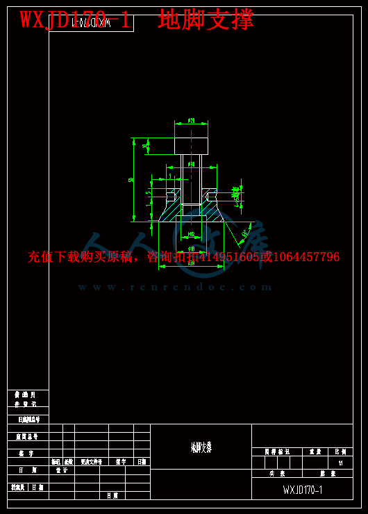
WXJD170-1 地脚支撑.dwg
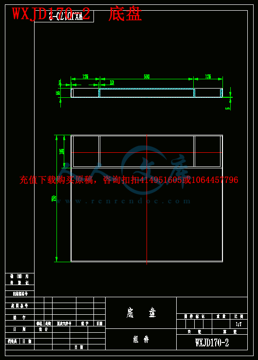
WXJD170-2 底盘.dwg
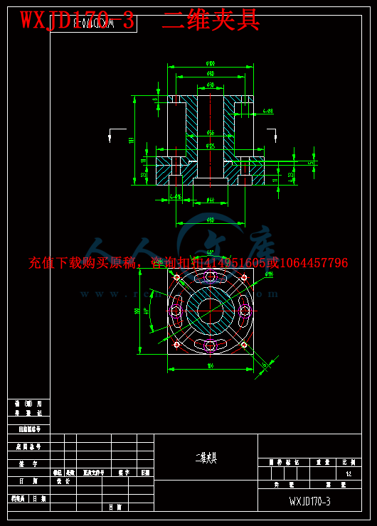
WXJD170-3 二维夹具.dwg
WXJD170-4 固定机架.dwg
WXJD170-5 绕线轮.dwg
WXJD170-6 气动涨紧轮.dwg
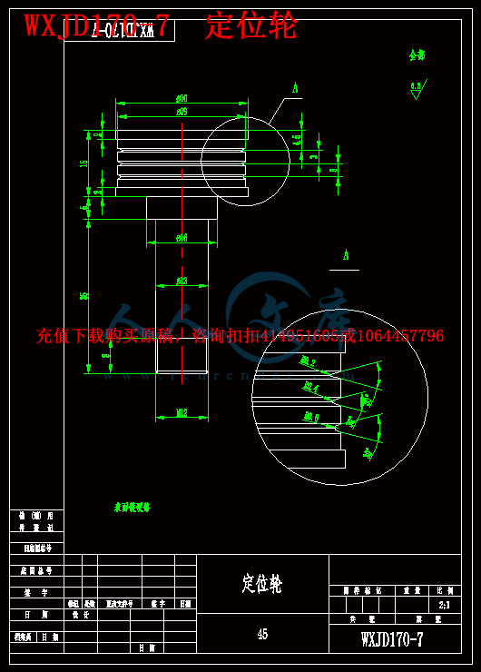
WXJD170-7 定位轮.dwg
WXJD170-8 X轴移动平台.dwg
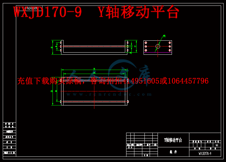
WXJD170-9 Y轴移动平台.dwg
参考图.jpg
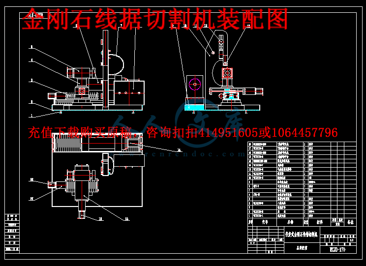
金刚石线据切割机装配图.dwg
压缩包内文档预览:(预览前15页/共30页)
预览图 预览图 预览图 预览图 预览图 预览图 预览图 预览图 预览图 预览图 预览图 预览图 预览图 预览图 预览图
编号:470679    类型:共享资源    大小:2.14MB    格式:RAR    上传时间:2015-08-09 上传人:好资料QQ****51605 IP属地:江苏
90
积分
关 键 词:
金刚石 切割机 设计 全套 cad 图纸 毕业论文 原创 资料
资源描述:

金刚石线锯切割机设计

【摘要】  本文对金刚石线锯切割机进行了深入的研究。在理论上探讨了单晶硅各异性材料特性对电镀金刚石线锯切割硅晶片过程影响。分析了锯丝沿不同的晶面、晶向锯切对晶片的影响规律,并推荐了首选的锯丝切入方向。研究发现,在确定的工艺参数下,当锯丝切入方向使锯切两边材料的弹性模量分布关于锯丝切入方向呈对称性时,可有效地提高晶片面形质量。锯丝切入方向与被锯切晶面内的易开裂方向一致时,可有减少晶片表面破碎。

   本课题主要对切割机导轨平台、工件夹具、缠绕筒及切割线张力调整装置的结构设计。通过搜集相关文献资料,了解本课题国内外研究动态,确定设计研究方案;完成金刚石线锯切割机滚珠丝杠、螺母、步进电动机、螺母等相关零部件及装配图的设计;完成相关零部件设计说明书及其图纸。


【关键词】  金刚石;线锯切割机;导轨平台


Design of Diamond Wire Cutting Machine

【Abstract】   In this paper, diamond wire saw cutting machine has conducted in-depth research. In theory of monocrystalline silicon anisotropic material properties of electroplated diamond wire saw cutting silicon wafer process affect. Wire sawing along the crystal surface, crystal and recommend a preferred saw Siqie into the direction of the influence of sawing the wafer. The study found that, when the saw wire into the direction of the cutting material on both sides of the elastic modulus distribution symmetrical saw cut wire into the direction, which can effectively improve the quality of the wafer surface shape to determine the process parameters. The saw wire into the sawing crystal surface easy to crack the same direction, the direction, may have to reduce the wafer surface broken.

   The main subject of the cutter rail platform, work holding, reel and cutting thread tension adjusting device structure design. Through the collection of relevant literature, research trends about this topic, and to determine the design of research programs; completion of the diamond wire saw cutting machine ball screws, nuts, stepper motors, nuts and other related parts and assembly drawings of design; complete the relevant parts design specification and its drawings.


【Key Words】   Diamond;Wire Saw Cutting Machine;Rail Platform

目 录

1 绪 论1

1.1 概述1

1.2 国内外研究现状及发展趋势1

1.3 金刚石线锯切割机的简介4

2 金刚石线锯切割机的设计方案5

2.1 有关首选参数5

2.2 切割机特点6

2.3 金刚石线锯切割机设计方案6

2.3.1 原理分析和总体结构设计7

2.3.2 传动系统和工作台的设计7

2.3.3 张力调整装置设计8

3 金刚石线锯切割机传动设计10

3.1 滚珠丝杆的选择与计算10

3.1.1 滚珠丝杆的定义10

3.1.2 滚珠丝杆副间隙调整法11

3.1.3 滚珠丝杆的循环方式13

3.1.4 滚珠丝杆的计算14

3.1.5 滚珠丝杆安装方式17

3.2步进电动机的选择18

3.3张紧轮设计21

3.4绕线轮的设计25

3.5二维夹具的设计27

结 论28

参考文献29

致 谢30


1 绪 论

1.1 概述

   脆性材料,如单晶硅、多晶硅、宝石、玻璃、陶瓷等,具有优良、稳定的物理和化学性能耐磨损性、抗腐蚀性、电绝缘性等,在电子、光学及其它领域得到广泛应用,特别是单晶硅、多晶硅、陶瓷材料被广泛用于太阳能光伏产业、半导体、真空电镀等高精端产业中。伴随半导体、光伏材料技术的发展,需求量不断增加,切割加工量大幅增长,由于硬脆材料硬度高、脆性大,因此加工难度较大。锯切是硬脆材料机械加工的第一道工序,锯切加工成本约占加工总成本的50%以上,因此,切割工艺、工具及设备受到越来越广泛的关注,并得到迅速发展[1]。金刚石线锯切割机是近十几年来获得快速发展的一种硬脆材料切割设备,包括使用游离磨料和固结磨料两类。根据锯丝的运动方式和机床结构,也可分为往复式和单向线锯。金刚石线锯使用高硬度的金刚石作为磨料,其典型磨粒尺寸为数十个微米,同时具备线锯切割的特点,能够对硬脆材料进行精密、窄锯缝切割,且可实现成形加工。随着在大尺寸半导体和光电池薄片切割中的应用和发展,金刚石线锯逐渐显现出一系列无可比拟的优点:加工表面损伤小、挠曲变形小,切片薄、片厚一致性好,能切割大尺寸硅锭,省材料、效益高,产量大,效率高等[2]。

内容简介:
毕业设计(论文) 译文及原稿 译文题目 : 线锯 过程中凹凸不平面 的 损伤情况 原稿题目 : Roughness Damage Evolution Due to Wire Saw Process 原稿 出处 : Egemen Teomete , International Journal of Precision Engineering and Manufacturing, 2011, 12(6): 941-947 nts浙江工业大学之江学院毕业设计(论文) 外文翻译 1 线锯过程中凹凸不平面的损伤情况 摘要 : 线锯工艺被 被广泛用于硅晶片生产与高收益、 低表面损伤 的 太阳能电池和微电子产业。 这个线锯过程 是 用于机器 切割脆性材料从而得到高 韧性 , 高 收益和低表面损伤的。线锯工艺也可用于切割混凝土和岩石,土木工程 。 在这研究中,通过改变工艺参数进行了试验参数的研究,以确定表面粗糙度损坏 。延性 材料 的穿晶 断裂和脆性断裂的晶间破坏 的切割表面可以在电子显微镜照片中观察到。涉及 粗糙度破坏过程 的损伤模型的参数是 可以得到的。 这个损伤模型预测粗糙度损害令人满意。 该 模型显示这种 粗糙度损伤 比率 是 进给速度 与 线速 度成正比 。提高效率的过程在 于 不增加粗糙度损伤 而通过增加进给速度 正比线速 度的比率 。 线张力不影响粗糙度损伤。 但是,导 线的 性能影响 粗糙度损伤。导线的 砂砾半径 越小和 砂粒间距 越短则 粗糙度损伤 越少 。 关键词 : 陶瓷, 损伤模型 , 韧性加工 , 粗糙度 , 线锯 1 介绍 硅晶片用于太阳能电池和微电子学产业可以减少从硅晶体使用内径 (ID)锯 或线锯。 线锯的 优势 是 ID 可以 看见。这些优点是更高的生产力 , 更少的晶片表面损伤和较低的切口损失。此外 , 晶片的直径可以 被 切 成 一个线锯高于一个 ID。线锯 适用 切割蓝宝石 , 碳化硅 , 锂铌酸 , 木材 , 岩石和几乎所有种类的陶瓷 , 包括 泡沫陶瓷 。 穆勒指出,线锯过程中的成本 是 占 硅晶片生产的总成本 的 30 , 这直接影响 整个 行业。所以 有必要来 采取 优化过程 的 措施 : 通过发展模型相关的工艺参数 ,产品质量和 过程效率 。 20 世纪 90 年代 , 早期的线锯 是在晶圆生产 裸钢丝和磨料泥浆 过程中开发的 , 在研磨加工 中 使用弹性流体动力。研磨颗粒可以 是 SiC 或钻石 , 用 30至 60的磨料颗粒的粒度可以是 5 30m体积分数的料浆 。 平均线直径是 180 m, 切缝损失 为 200到 250 m。浆料可以是水 性 或油 性的 。油 性 泥浆使 溶液彼此互溶, 很难独立 , 而从晶圆片表面清除油 状物 是另一个问题。油 性泥浆的 使用处 理也 是一个问题。 产生的 氢气 和 水 性 泥浆 中 硅的相 互作用可能会导致爆炸。然而 , 从环保的角度来看 , 考虑到 高数量的泥浆处理过程, 水性 通常是优选的 。 Clark 等人说,为了提高生产率和能够削减更硬的 陶瓷,开发了镶金刚石线 。 其适用于 磨削加工 。 在 自由磨料线锯 中 ,送丝速度为 5 15 米 /秒, 线张力为 20 30N。 在电线弓 中,其结果 使得所述导线 达到 2 度 到 6 度 的水平。在 研磨加工工艺的线锯 中 ,线速度较低的材料去除是不会发生水动力作用 的 。 线锯过程 的研究 已经持续 在 三 个 主要领域:材料去除机制,运动学,进程之间的输入和输出参数的研究。 nts浙江工业大学之江学院毕业设计(论文) 外文翻译 2 Li 等人提出了磨料颗粒的 受应力作用 是滚动和缩 进的线锯的过程。穆勒 提出的材料去除机制对于自由磨料加工开发 利 用断裂力学和流体动力学行为的浆料。 材料去除率的定义是作为一个功能 电源提供给磨料流体动压效应与流体膜性能 。它 的计算采用有限元 阀 夫妇雷诺方程, 流体力学与弹性力学方程 。 刘等人 指出,材料去除机理 线锯切割岩石是赫兹类破裂 ,其中 破裂 的发生是由于拉伸后面滑珠 引起的 。 魏和高从事分析直线的刚度和 研究在张力作用下的导线,还有 振动特征 对线速度,张力,和浆料粘度的研究 。 当 线速度 低于 25 米 /秒 时, 增加 线张力和浆粘度 而降低振幅和切口损失,对它 几乎 没有影响。 Clark 等人 监测线锯过程,线速度,送丝速度 和线的张力。 Clark 和 Hardin 等人还进行了 参数研究有关工艺 的 参数,表面粗糙度和线切割泡沫陶瓷 ,木材。他们还 进行了与一个固定的磨料切片单晶 SiC 的参数 研究, 研究 金刚石线有关的线速,摇摆频率, 下表面和亚表面损伤的进给速度。 Meng 等人研究了闭环金刚石绳锯切割和浸渍氧化铝陶瓷粉末。 硬度各向异性的铌酸锂晶片已经被应用在 纳米压痕 中 。 Bhagavat 和 Kao 确定 了三个最常见的取 向的方法 。他们通过切片 硅晶体 的 各向异性来确定的方向 。 硅片的钢丝锯 对 光伏及半导体行业 有着 重大 的 利益 关系。半 导体有严格的公差和表面质量 要求 。 从现有的模拟 脆性材料压痕损失 中 可以看出 在加工脆性材料时的损坏情况。脆性材料的压痕 存在几种的失效 模式 。 Ryu 等人研究了硅片,玻璃和碳化硅 上的压痕 。 赵等人观察到在地面上被 破坏 的 光学玻璃表面的 压痕 。 不同的研究人员 对延性域磨削脆性材料 进行了试验研究。 Bifano 等人指出 在研磨中, 当进给 量减少到一定量时,磨损机制就可以实现 从脆性到韧性 转变 。 在这项研究中 , 一个 线锯 损伤模型 可以看出线锯过程中粗糙度的损坏 。这个损伤模型是基于 延性去除模式 和脆性 损 害 模式 ,观察 扫描电镜 中切割面的图像。 过实验测定, 用损伤模型来预测 损害 通是 可靠的 。第二节提出了这个实验工作。 第三节提出了该模型 。第四节提出了结果和讨论的研究。在第五部分 提出 这个结论。 2 实验过程 线锯的实验 是在 氧化铝陶瓷 上进行的 。 在 线锯切削试验 中 测量 了 丝弓角,轴向线速度 Vx 和进给速率 Vz。 同时也 测量 了 切断面 表面的粗糙度,还 得到 了 扫描电镜成像的切表面。在这些测量中所使用的设备本节介绍及工艺参数。 2.1 线锯切割和丝弓角测量 nts浙江工业大学之江学院毕业设计(论文) 外文翻译 3 图 1 单丝,阀芯阀芯线锯机 ,该线轨道,由虚线标记。( DWT 公司, 千禧年生产 的 模型, 美国科罗拉多州 Springs,美国) 实验 中 使用 线锯设备 ( 其 模型 是千禧年在 科罗拉多州斯普林斯 应用 钻石线技术生产的 ) 。 这种 阀芯 对 阀芯 的 线锯机 摇摆运动的线可控制 线速度 Vx,进料速度 Vz 和线张力 T。张力由 紧 线 滑轮控制 , 由 气压力驱动, 而摆动 如图 1 中可以看出。 导线的切割长度为 300 英尺( 91.4 米 ) 。因此,在每一个方向逆转, 300 英尺的线是从一个线轴 转移到 其他的 线轴 。 在切割过程中使用 的 冷却剂包括水 和 润滑剂 Sawzit( 合成润滑剂 公司的产品) ,它们 的比例为 50/1。 线锯实验使用了 四种不同的金刚石涂层钢线。 平均半包括磨粒的角度 DWS2 是 =71 度 。这个金 刚石粒度的镀层钢丝 DWS3 是金刚石 线 锯公司的一个产品 。 涂 金刚石 砂砾的钢丝 DWS4和 DWS5是 圣戈班 磨料磨具公司 的产品 。 DWS4和 DWS5是用 镍电镀钢 制造的。 磨粒被贴到电镀 。 nts浙江工业大学之江学院毕业设计(论文) 外文翻译 4 镍层,而核心依然完整 。 氧化铝陶瓷样品 的 抗拉强度 =300MP,断裂韧性 K=4MPam(1/2),杨氏模量电子 E=370GPa 时 , 硬度 H=22GPa,它 用于对加工对象物的切削的测试 。切割样 品的长度 是在 1520 毫米 之间, 高度 7.1 毫米。 一组测试完成 DWS2 的线速度变化 Vx=1.3,1.8, 2.95, 3.5 米 /秒,线张力变化 T=13.3, 17.8, 22.4, 26.7 牛 ,和 下料速度 变化 Vz=5,6.35, 10.16 微米 /秒。 为了探讨不同 特性对表面质量 影响 ,每个线进行了四次试验 ,在 工艺参数 Vx=1.35, 2, 3, 4 米 /秒, Vz=6.35 米 /秒, T=13.3N 下分别 使用电线 钢丝DWS3, DWS4 和 DWS5。 图 2 线钢丝锯弓角测试 用 一个 2856 2142 像素 的 数码相机(柯达易购 DX7630)来 测量 丝弓 角 ,其 角度 如图 2。图像的线和样品收集过程如图 3。 氧化铝陶瓷 SEM 图像的线锯切割表面的( Vx=1.3 米 /秒, Vz=5 微米 /秒, T=13N)试 验和分析用 数字图像处理 ( Mathworks公司)获得的角度 在 导线和水平之间 。平均稳态丝弓角的测试, 达到 了 稳定状态丝弓角 的 要求。 2.2 表面粗糙度测量和扫描电镜成像 切割表面的表面粗糙度的测定使用非接触式的光学轮廓仪, Zygo 公司生产 的Zygo 新查看 6000。 10 倍的镜头用于测量。 轮廓的垂直分辨率是 3 纳米的分辨率,在nts浙江工业大学之江学院毕业设计(论文) 外文翻译 5 水平面上为 1.1 微米 ,而 视野使用 0.7 0.53 毫米。 在一个探针 测量 中 ,需要连续的轮廓测量每个 0.7 0.53 毫米 ,将这些数据结合在一起成 为 一个数据集。 三针测量,是指测量 每个 0.7 3 毫米 尺寸,常应用在 每个样品的切割方向 的左中 右的切割表面。 经过 测量后,用 版本 8.1.5Zygo 公司开发的MetroPro 软件 进行 数据处理 , 施加 高通滤波,以除去表面的波状起伏。 中心线 的算术平均 偏离 就可以获得最佳拟合平面 。 三次测量的平均值作为表面粗糙度( Ra)的测试值 。 图 3 氧化铝陶瓷的线锯切割表面的 SEM 图像( Vx=1.3 米 /秒, Vz=5 微米 /秒, T=13N) 扫描电子显微镜( SEM), JEOLJSM-606LV, 用于图像的切割面拓扑。 SEM 图像的来自 中心线的切割表面 上,少于 一半的样本 。由 图像 可知 材料去除的 机制是 穿晶断裂 的 。 同时, 也 可以 观察到 晶间破坏 的 断裂 模式。 这两种机制中可以看图 3。 ntsINTERNATIONAL JOURNAL OF PRECISION ENGINEERING AND MANUFACTURING Vol. 12, No. 6, pp. 941-947 DECEMBER 2011 / 941DOI: 10.1007/s12541-011-0126-4 NOMENCLATURE Fz = Vertical force on a grit Fzg= Force on a single grit Fzs = Total vertical force action on sample y= Yield stress R = Grit radius h = Cut depth for a single particle Vx = Wire speed Vz = Feed speed T = Wire tension Ap= Projected area of the cut trench Lo= Cut length of sample Lg= Distance between cutting particles D = Width of cut trench S = Sliding distance c = Median crack length = Half of the included angle of the grits E = Modulus of elasticity of ingot H = Hardness of the ingot P = Indentation force Kc= Fracture toughness of the ingot w = Distributed wire load on the sample N = Number of cutting particles in the cut length = Wire bow angle 1. Introduction Silicon wafers used in the solar cell and microelectronics industries can be cut from silicon crystals using inner diameter (ID) saw or wire saw. Wire saw has advantages over ID saw. These advantages are higher productivity, less wafer-surface damage, and lower kerf loss.1Moreover, the diameter of wafer that can be sliced by a wire saw is higher than that obtainable by an ID saw. Wire saws are used to cut sapphire, silicon carbide, lithium niobate, wood, rock, and almost all kinds of ceramics, including foam ceramics.1-3Moller4stated that the wire saw process is responsible for 30% Roughness Damage Evolution Due to Wire Saw Process Egemen Teomete1,#1 Dept. Civil Engineering, Dokuz Eylul University, Kaynaklar Campus Buca, Izmir, Turkey, 35160# Corresponding Author / E-mail: eteomete, TEL: +90-232-4127060, FAX: +90-232-4531192KEYWORDS: Ceramic, Damage model, Ductile regime machining, Roughness, Wire sawThe wire saw process is widely used for silicon wafer production with high yield and low surface damage in solar cell and microelectronics industries. The wire saw process is used to machine brittle materials in the ductile regime where high yield and low surface damage are desired. The wire saw process is also used to cut concrete and rocks in civil engineering. In this study, an experimental parametric study was conducted by varying process parameters to determine surface roughness damage. Ductile regime material removal by trans-granular failure and brittle fracture by inter-granular failure are observed in electron micrographs of the cut surfaces. A damage model that relates the roughness damage to process parameters was derived. The damage model predicts the roughness damage satisfactorily. The model shows that the roughness damage is proportional to the ratio of feed speed to wire speed. Improvement in the efficiency of the process without increasing the roughness damage can be attained by increasing the feed speed proportionally to wire speed. Wire tension does not affect roughness damage. Roughness damage, however, is affected by properties of the wire. Wires having smaller grit radius and small grit spacing cause less roughness damage. Manuscript received: May 4, 2010 / Accepted: May 15, 2011 KSPE and Springer 2011 nts942 / DECEMBER 2011 INTERNATIONAL JOURNAL OF PRECISION ENGINEERING AND MANUFACTURING Vol. 12, No. 6of the total silicon wafer-production cost, which directly affects industry. There is a need to optimize the process by developing models relating process parameters to product quality and process efficiency measures.4Early wire saw processes for wafer production developed in the 1990s consisted of a bare steel wire and abrasive-carrying slurry, resulting in free-abrasive machining using elasto-hydrodynamic forces.5,6The abrasive particles can be SiC or diamond. The mean grit size of abrasive particles can be 5 to 30m with a 30% to 60% volume fraction in the slurry. Average wire diameter is 180 m, leading to a kerf loss of 200 to 250 m. The slurry can be water based or oil based. Oil-based slurry causes the wafers to stick to each other, and it is hard to separate them, while removal of the oil from the wafer surface is another problem. Disposal of the oil-based slurry after use is also a problem. Hydrogen gas produced from the interaction of water-based slurry and silicon may cause explosions. However, from an environmental point of view, considering the high amount of slurry disposed of during the process, water-based slurries are generally preferred.4Clark et al.5stated that in order to increase the productivity and to be able to cut harder ceramics, diamond-impregnated wire, which leads to fixed-abrasive machining, was developed. In wire sawing with free abrasives, wire speed is between 5 to 15 m/s and wire tension is 20 to 30 N. The feed into the ingot results in a wire bow so that the wire makes 2oto 6owith the horizontal.6In the fixed-abrasive machining wire-saw process, the wire speed is lower as material removal is not occurring by hydrodynamic action. In multi-wire technology, a single wire is winded to a tension control unit and several guide pulleys, which are grooved with constant pitch. Five to seven hundred parallel wires run together and are collected at a take-up spool. The ingot is sliced into hundreds of wafers as it is fed into the wire web. The wafers in solar-cell industry are cut by running the wire in only one direction at a high speed between 5 to 20 m/s, while the wafers in the micro electronics industry are cut by running the wire in both directions with a lower speed (oscillating the wire from one spool to another).4Research on the wire saw process has been ongoing in three main areas: material removal mechanisms, kinematics of wires, and parametric studies between the process inputs and outputs. Li et al.7presented the stresses under an abrasive particle, which is rolling and indenting in a wire saw process. Material removal mechanisms for free-abrasive machining were developed using fracture mechanics and hydrodynamic behavior of slurry by Moller.4The material removal rate is defined as a function of power supplied to the abrasive by hydrodynamic effect and the hydrodynamic film properties are calculated using the finite element method which couples Reynolds equation of hydrodynamics with the elasticity equation of wire.6Liu et al.8stated that the material removal mechanism of bead- impregnated wire-saw cutting of rock is a Hertzian type fracture in which the fracture occurs due to the tensile field behind the sliding bead. Wei and Kao9worked on stiffness analyses of straight and bowed wires under tension. Vibration characteristics of wire with respect to wire speed, tension, and slurry viscosity was investigated. The increase of wire tension and slurry viscosity decreases vibration amplitude and kerf loss, while the wire speed has almost no affect when it is below 25 m/s.1,10Process monitoring of the wire saw for forces, wire speed, feed rate, wire bow, and wire tension was developed by Clark et al.5Parametric studies relating process parameters to forces, and surface roughness and wire wear for cutting foam ceramics and wood were conducted by Clark et al.2Hardin et al.11conducted a parametric study for slicing single crystal SiC with a fixed-abrasive diamond wire, relating wire speed, rocking frequency, and down-feed rate with surface and subsurface damage. Closed-loop diamond- impregnated wire saw cutting of Al2O3and TiC ceramics was studied by Meng et al.12Hardness anisotropy of Lithium Niobate wafers has been investigated using nano-indentation.13Bhagavat and Kao14determined the direction of approach for three most commonly sliced orientations of silicon considering crystal anisotropy. Damage evolution due to wire sawing of silicon wafers is of significant interest as the photovoltaic and semiconductor industries have strict tolerances for surface quality. The process-induced damage on brittle materials can be modeled starting with existing damage models of indentation of brittle materials. There exist several models for the failure mechanisms in brittle materials due to indentation.15-20 Ryu et al. studied indentation on silicon wafer, glass and silicon carbide.21 Zhao et al. observed the indentation damage modes on ground surface of optical glass.22Ductile regime grinding of brittle materials has been investigated experimentally by different researchers.23-28Bifano et al.24stated that when the feed is decreased below a certain amount in grinding, a transition of wear mechanism from brittle to ductile mode can be achieved. In this study, a damage model for wire saw process induced roughness damage is developed. The damage model is based on ductile mode material removal and brittle mode damage, as observed in SEM images of cut surfaces. The damage model predicts the experimentally measured damage successfully. The experimental work is presented in section 2. The model is presented in section 3. The results and discussion of the study are presented in section 4. The conclusions are presented in section 5. 2. Experimental Process Wire saw experiments were conducted on alumina ceramic. The wire bow angle, wire axial speed, Vxand feed rate, Vzwere measured during the wire saw cutting tests. The surface roughness of cut surfaces was also measured. The SEM imaging of cut surfaces was obtained. The equipment used in these measurements and the process parameters are presented in this section. 2.1 Wire Saw Cutting and Wire Bow Angle Measurement A wire saw machine (Millennium model produced by Diamond Wire Technology in Colorado, Springs) was used in the experiments. This spool-to-spool wire saw machine with rocking motion of the wire can be controlled by the wire speed, Vx, down-ntsINTERNATIONAL JOURNAL OF PRECISION ENGINEERING AND MANUFACTURING Vol. 12, No. 6 DECEMBER 2011 / 943feed speed, Vz, and wire tension, T. The tension was controlled by wire tension pulleys powered by air pressure, while the rocking motion was controlled by wire guide pulleys as can be seen in Fig. 1. The cut length of the wire was 300 ft (91.4 m). Thus, at every direction reversal, 300 ft of wire was transferred from one spool to the other. A coolant consists of water-to-lubricant Sawzit (Product of Synthetic Lubricants, Inc.) ratio of 50/1 was used during cutting tests. Four different diamond grit coated steel wires were used in the wire saw experiments. The average half-included angle of the grits on DWS2 was =71o. The diamond-grit-coated steel wire DWS3 was a product of Well Diamond Wire Saws Inc. Diamond-grit-coated steel wires DWS4 and DWS5 were products of Saint-Gobain Abrasives Inc. The DWS4 and DWS5 were manufactured by nickel electroplating on steel. The grits were affixed into the electroplated nickel layer, while the core remains intact. Alumina ceramic samples having tensile strength of fr=300 MPa, fracture toughness KIC=4 MPam1/2, Youngs modulus of E=370 GPa,29and hardness of H=22 GPa20were used in the cutting tests. The cut length of the samples was between Lo =1520 mm and the height was Hs =7.1 mm. A group of tests were done with DWS2 with the wire speed varied over Vx=1.3, 1.8, 2.95, 3.5 m/s, the wire tension varied over T=13.3, 17.8, 22.4, 26.7 N, and the down feed varied over Vz=5, 6.35, 10.16 m/sec. In order to explore the effect of different wires characteristics on surface quality, twelve tests were done with process parameters Vx=1.35, 2, 3, 4 m/s, Vz=6.35 m/sec, and T=13.3 N using the wires DWS3, DWS4, and DWS5; four tests were conducted with each wire. A megapixel digital camera (Kodak Easy Share DX 7630) of 2856 2142 pixels was used to measure the wire bow angle seen in Fig. 2. The images of the wire and sample were collected during the test and analyzed using Matlab (Mathworks) to obtain the angle between the wire and the horizontal. The average of the steady state wire bow angles, , was attained to the test as the steady state wire bow angle of that test. 2.2 Surface Roughness Measurements and SEM Imaging The surface roughness of the cut surfaces were measured by using an optical non-contact profilometer, Zygo New View 6000, manufactured by Zygo Corporation. A 10x lens was used for the measurements. The profilometer had a vertical resolution on the order of 3 nanometer; the resolution in the horizontal plane was 1.1 m, while the field of view used was 0.70.53 mm. In a stitch measurement, the profilometer takes continuous measurements each 0.70.53 mm and stitches them together into one data set. Three stitch measurements, each of 0.73 mm dimensions, were applied in the direction of cutting for each sample on the left-middle-right of the cut surface. After the measurements were taken, the data was processed using the software MetroPro Version 8.1.5 developed by Zygo Co. A high pass filtering was applied to remove the surface waviness. Arithmetic average deviation from the centerline (best fit plane) was obtained. The average of three measurements was taken as surface roughness (Ra) of the test. A Scanning Electron Microscope (SEM), JEOL JSM-606LV, Fig. 1 Single wire, spool-to-spool wire saw machine. The wire track is marked by the dashed line. (DWT Inc., Millennium Model, Colorado, Springs, USA) Fig. 2 Wire bow angle in wire saw tests Fig. 3 SEM image of a wire saw cut surface of alumina ceramic(Vx=1.3 m/sec, Vz= 5 m/sec, T=13 N) nts944 / DECEMBER 2011 INTERNATIONAL JOURNAL OF PRECISION ENGINEERING AND MANUFACTURING Vol. 12, No. 6was used to image the cut-surface topology. The SEM images were taken from the lower half of the sample, on the center line of the cut surface. It is seen from the images that the material removal mechanism is the trans-granular failure. Inter-granular failure, in which grain boundary failure results in grain dislodgement in a brittle mode, is also observed. Both mechanisms can be seen in Fig. 3. 3. Roughness Model Derivation Ductile material removal and brittle fracture is observed in SEM images. The proposed model is shown in Fig. 4. The material removal occurs in a ductile mode as seen in SEM images, while the damage occurs due to median cracking as in Fig. 4. As discussed by Evans and Marshall,15removal of plastically deformed material in the cutting zone reduces residual stress. This reduces the tendency of lateral crack formation in brittle materials. Fu et al.30derived the force on a single grit in ductile mode material removal as presented in Eq. (1), where yis yield stress, R is cutting particle radius, and h is cut depth for a single particle. zzg yFF Rh= (1) The mass continuity of the cutting process gives us Eq. (2). ogz xpo ggLDhsLd Vol d dS h hVVdt A dt L D dt L L = = (2) Volume is the total amount of material removed, Apis the projected area of the cut trench, Lois the cut length of sample, Lgis the distance between cutting particles, D is width of cut trench that can be taken as diameter of wire, S is sliding distance, Vx is the axial speed of wire, and Vzis the feed of wire. The force on a single grit, Fzg,can be obtained in terms of process parameters by using Eq. (1) and Eq. (2). zzg y gxVFRLV= (3) The damage resulting from wire saw cutting is correlated with median crack depth. Lawn et al.16derived the median crack length using fracture mechanics principles. The median crack length is presented in Eq. (4). Lawn et al.16calibrated the indentation coefficients 0.032 and 0.017 in Eq. (4) using indentation data of soda-lime glass and noted that they are applicable to all brittle materials. 21 32230.032 0.017 (cot )cEPcHK=+(4) Inserting Eq. (3) in place of P=Fzgin Eq. (4) gives us Eq. (5). 221 323230.032 0.017 (cot )ygzcxRLEVcHKV=+(5) Fig. 4 Wire saw roughness damage model: ductile material removal and brittle fracture The damage due to the wire saw process is presented in terms of the process parameters in Eq. (5). The damage is a function of the half of the included angle of the grits, ; the modulus of elasticity of ingot, E; the hardness of the ingot, H; the fracture toughness of the ingot, Kc; and wire properties, feed speed, and wire speed. 4. Results and Discussion Decreasing feed rate in grinding below a threshold yields ductile regime grinding of brittle materials.23-28In ductile regime machining of brittle materials, the material removal takes place with plastic deformation of the grains.23,24,26-28,31While the material removal is in ductile mode, brittle fracture is still observed in ductile regime grinding.24,28The material removal and damage formation in the wire saw process is analogous to ductile regime grinding as seen from SEM images of wire saw processed surfaces. A damage model is derived for roughness damage induced by wire saw process. The model is compared to experimental data in Fig. 5. The model has a good performance in predicting roughness damage due to the wire saw process. The damage model states that if the feed-speed-to-wire-speed ratio (Vz/Vx) is increased, the roughness damage will increase, while if this ratio is kept constant, roughness damage will be constant. The two experiments marked in Fig. 5 have different feed speeds and wire speeds but a very close (Vz/Vx) ratio, and their roughnesses are also very close to each other. In a wire saw process, if efficiency should be increased by increasing the feed speed, in order to keep the level of damage constant, the wire speed should be increased proportionally to the feed speed. In order to explain the effect of wire tension on roughness damage, the change of forces with wi
温馨提示:
1: 本站所有资源如无特殊说明,都需要本地电脑安装OFFICE2007和PDF阅读器。图纸软件为CAD,CAXA,PROE,UG,SolidWorks等.压缩文件请下载最新的WinRAR软件解压。
2: 本站的文档不包含任何第三方提供的附件图纸等,如果需要附件,请联系上传者。文件的所有权益归上传用户所有。
3.本站RAR压缩包中若带图纸,网页内容里面会有图纸预览,若没有图纸预览就没有图纸。
4. 未经权益所有人同意不得将文件中的内容挪作商业或盈利用途。
5. 人人文库网仅提供信息存储空间,仅对用户上传内容的表现方式做保护处理,对用户上传分享的文档内容本身不做任何修改或编辑,并不能对任何下载内容负责。
6. 下载文件中如有侵权或不适当内容,请与我们联系,我们立即纠正。
7. 本站不保证下载资源的准确性、安全性和完整性, 同时也不承担用户因使用这些下载资源对自己和他人造成任何形式的伤害或损失。
提示  人人文库网所有资源均是用户自行上传分享,仅供网友学习交流,未经上传用户书面授权,请勿作他用。
关于本文
本文标题:金刚石线锯切割机设计【全套CAD图纸+毕业论文】【原创资料】
链接地址:https://www.renrendoc.com/p-470679.html

官方联系方式

2:不支持迅雷下载,请使用浏览器下载   
3:不支持QQ浏览器下载,请用其他浏览器   
4:下载后的文档和图纸-无水印   
5:文档经过压缩,下载后原文更清晰   
关于我们 - 网站声明 - 网站地图 - 资源地图 - 友情链接 - 网站客服 - 联系我们

网站客服QQ:2881952447     

copyright@ 2020-2025  renrendoc.com 人人文库版权所有   联系电话:400-852-1180

备案号:蜀ICP备2022000484号-2       经营许可证: 川B2-20220663       公网安备川公网安备: 51019002004831号

本站为文档C2C交易模式,即用户上传的文档直接被用户下载,本站只是中间服务平台,本站所有文档下载所得的收益归上传人(含作者)所有。人人文库网仅提供信息存储空间,仅对用户上传内容的表现方式做保护处理,对上载内容本身不做任何修改或编辑。若文档所含内容侵犯了您的版权或隐私,请立即通知人人文库网,我们立即给予删除!