设计说明书.doc

中型客车车门总成设计【6张CAD图纸+WORD毕业论文】【车辆专业】

收藏

压缩包内文档预览:(预览前20页/共25页)
预览图 预览图 预览图 预览图 预览图 预览图 预览图 预览图 预览图 预览图 预览图 预览图 预览图 预览图 预览图 预览图 预览图 预览图 预览图 预览图
编号:471527    类型:共享资源    大小:877.94KB    格式:RAR    上传时间:2015-08-12 上传人:好资料QQ****51605 IP属地:江苏
45
积分
关 键 词:
中型 客车 车门 总成 设计 全套 cad 图纸 word 毕业论文 车辆 专业
资源描述:

摘 要


乘客门是客车的重要组成部分,是乘客上下车的通道,对客车的整体造型也起着重要的协调作用。随着我国汽车技术的发展,我国汽车厂家已普遍采用了优势突出的外摆式乘客门。外摆式乘客门是一种无轨道的移出车门,门扇靠回转臂支撑,依靠转轴的转动带动门扇作近似于平行移动的运动,因而也称为平移门。

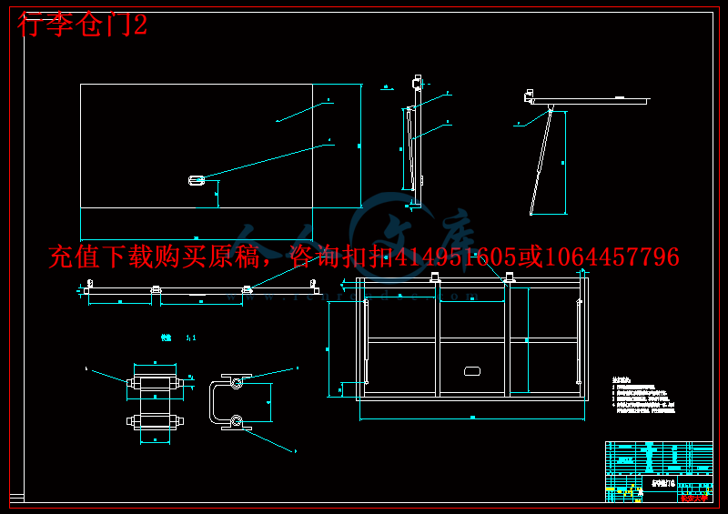
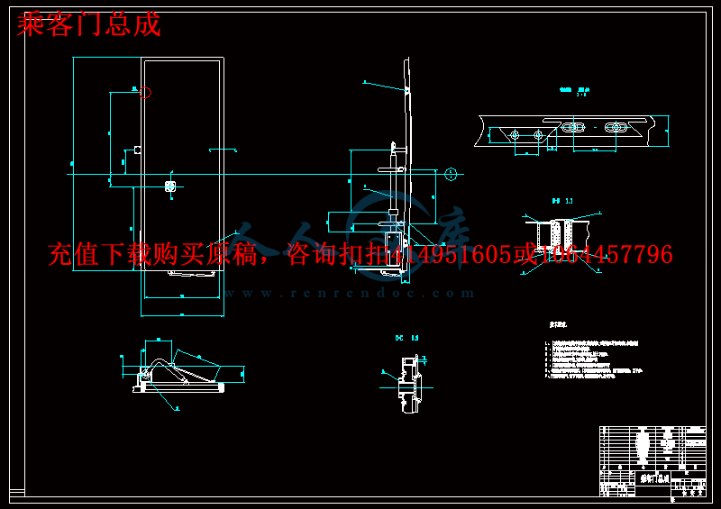
本文为中型客车的外摆式乘客门和行李舱门的设计。分析了外摆式乘客门和行李舱门的结构和工作原理,确定其各部分的尺寸及主要零部件的选型及安装。讨论了国内外汽车附件工业发展的情况比较。AUTOCAD软件是当今世界上一种主流的设计软件之一。在本设计中应用了AUTOCAD软件制作乘客门和行李舱门。


关键词: 外摆门,行李舱门, 安全,AUTOCAD。


Abstract


Passenger door is the important department of the coach, is the route way for the passengers. And assort with the whole coach sculpt. With the development of our vehicle technology, the domestic vehicle factory has already adopted the outer turning service door. It has much more predominance. The outer turning service door is the door which has no tram road and parallel move out of the coach, the door was supported by the circumrotate arm. By the rotation of the circumrotate axes, the door is moving close to the parallel move. Thus this door is called translation door.

This paper introduces the design of the medium passenger train coach’s outer turning service door and the engine hatch door. Analyzed the structure and operating principles of the outer turning service door and the engine hatch door, determined the size of its parts and major components of the models and installation. Discussed the development of the vehicle annex industry. AUTOCAD software is one of a mainstream in the world of design software. During the design, the AUTOCAD software has been sued to product passenger door and baggage compartment door.


KEY WORDS: outer turning service door, baggage compartment door, safe, AUTOCAD。

目  录


第一章 绪论························································1

 1.1 乘客门类型选择················································1

1.1.1乘客门主要结构形式·········································1

1.1.2 外摆门的优点··············································2

 1.2 CAD 技术在汽车开发中的应用····································2

 1.2.1CAD技术的发展············································2

第二章  国内外外发展情况比较·······································3

2.1客车附件工业的特点···········································3

2.2 目前国内客车车身附件的状况及与国外发达国家之间的差距·········3

2.3发展建议·····················································6

第三章  外摆式乘客门设计···········································7

3.1 外摆式乘客门的结构···········································7

3.2乘客门泵选型··················································8

3.2.1 门泵主要技术参数··········································9

3.2.2 门泵安装与调试············································10

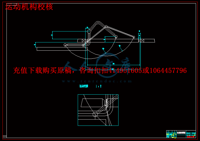
3.3运动机构设计及校核···········································10

3.3.1用作图法确定车门的运动轨迹·······························10

3.3.2运动校核··················································13

3.4 外摆门的密封·················································14

3.4.1几种典型外摆式乘客门密封结构·····························14

3.4.2改进型密封结构···········································16

3.4.3密封结构选定  ···········································17

3.5 外摆式乘客门的制作···········································18

3.5.1制作工艺·················································18

3.5.2预装与调试················································18

第四章  发动机舱门设计·············································18

4.1舱门结构组成·················································18

4.2零部件选型····················································18

4.2.1锁 具 的 选 择················································18

4.2.2气弹簧支撑机构·············································20

4.3铰链设计·····················································21

设计评价分析····················································23

致   谢··························································24

参考文献··························································25


一   绪 论

1.1客车乘客门类型选择

乘客门是客车的重要组成部分,是乘客上下车的通道,对客车的整体造型也起着重要的协调作用。客车外形是影响客车性能的一个重要因素。乘客门是车身外形的一个组成部分,它不仅与客车的动力性、经济性密切相关,而且直接影响客车外形的美观与动感。随着车速的不断提高,客车的空气动力性问题越来越突出。过去我国采用较多的是折叠式车门,由于车门内陷而增加了汽车的空气阻力,产生风流噪声,而且由于车门缝隙大,密封困难,在形式中产生强烈的振动噪声和漏尘,从而严重影响乘坐舒适性。导槽滚轮式乘客门虽然无内陷,但是在车身侧壁有导槽。因此,在的许多高档旅游客车和长途豪华客车上出现了一种使车身表面平整光滑的乘客门,外摆门成为代表乘客门发展的一种趋势。近年来,伴随着出城乡人民群众生活水平的不断提高和高速公路建设的完善,我国中、高档客车取得了长足的发展,外摆门已经在我国客车生产中得到广泛应用。

内容简介:
二 七 届 毕 业 设 计 中型客车乘客门和行李舱门设计 学 院:汽车学院 专 业:车辆工程 姓 名:钟 海 学 号: 2201030219 指导教师:郭应时 完成时间: 2007.06. 二七年六月 nts长安大学毕业设计(论文)开题报告表 课题名称 中型客车车门总成 设计 课题来源 自己选 定 课题类型 造型 设计 指导教师 郭应时 (老师) 学生姓名 钟 海 学 号 2201030219 专 业 车辆工程 (内容包括:课题的意义,国内外发展状况,本课题的研究内容、方法、手段及预期成果,任务完成的阶段安排及时间安排,完成任务所具备的条件因素等。) 一 课题的意义 乘客门是客车的重要组成部分,是乘客上下车的通道,对客车的整体造型也起着重要的协调作用。客车外形是影响客车性能的一个重要因素 。乘客门是车身外形的一个组成部分,它不仅与客车的动力性、经济性密切相关,而且直接影响客车外形的美观与动感。 二 国内外 发展状况 外 摆式乘客门有无轨道移出式车门和有轨道式车门,目前主要使用的是一种无轨道的移出车门,门扇 靠 回转臂支撑 ,依靠转轴的转动带动门扇作近似 于 平行移动的运动,因而也称为平移门 。 它主要由门扇、支臂、 导向拉杆、 锁止机构等 组 成。 车门门体采用轻质铝合金材料。门体骨架由铝合金型材经氩弧焊组焊而成,门体的内外蒙皮采用 1.0mm的薄铝板,使整个门体重量大大减轻。车门采用双层密封,双向的,镶嵌在铝 型材槽中的车门密封条很好的保证了车门的密封。车门开度大,开关轻便、灵巧、安全,车门关闭后,门体与整车外观协调,使整车的外表面平整,整车造型更加美观,既减小了空气阻力,又防止了高速行驶产生较大的风流噪声。 转轴、转臂、下拉杆与车门体相连接,不但起到支撑门体的作用,还利用四连杆机构原理来实现车门的无轨道平移。转轴与转臂均采用优质钢管,表面喷塑处理,使之与车内饰相协调。为了防止装配误差影响车门的运动,各传动杆件的铰接点均设计为可调节的结构,在安装中可通过适当的调整,以保证车门运动的准确性。 锁止机构是由装在门体两 侧的锁止块与安装在前后门框上的锁止块组成。当车门完全关闭后,由门泵转轴带动车门向上移动,锁止块相互锲合进入锁止状态。 随着国内客车行业迅速发展,中、高档次客车需求的不断增加,中、高档豪华客车的开发成为各客车生产厂家的热点。为了不断提高客车的豪华程度,大客车外摆门成为众多客车生产厂家关注的重点, 豪华型大客车采用外摆门成为一种趋势。 它与折叠式乘客门相比有以下优点: 1 外摆式车门是把车门整体旋转外移,车门开度大,可以开启到门框宽度,有效利用门框空间,使踏步宽敞,保证乘客上下车方便。 2 外摆门采用双层密封,具有良好的密 封性,密封结构简单。 3 车门开启和关闭的动作柔和,运动平顺,且设有防夹装置,开关方便、安全,操纵灵巧。 4 刚性较好、不易变形下沉,行车时不易产生振动噪声。 5 外形与整车协调,无凹陷,克服了凹陷于车身内的折叠式车门的空气涡流,改善了客车的空气动力学性能,行车时空气阻力小,风噪小,且造型美观,在客车高速运行时可以提高客车的经济性和功率利用率。 nts以前国产的大中型及轻型的客车上用得最多的是折叠式乘客门,但这种车门由于其运动特点限制了其门扇的形状只能是平板形的,而且其转轴必须垂直于地板。因此装上车身后,必然凹陷于车身内,无法与车身外形保持平齐。这样不仅从造型上显得不协调不美观,而且在行使时气流在凹陷处形成漩涡,影响整车的空气动力性,增加行驶阻力,产生风噪。而外摆门 克服了这些缺点,它 的这些优点使得它在各种客车上的应用更加广泛,在客车技术高速发展的今天,可以说代表着客车乘客门技术发展的一种趋势。 三设计内容 依据底盘总布置方案,在与车身总布置设计充分协 调的基础上,参考国内外现有同类车型的造型特征和相关结构,结合生产企业的工艺特点,确定所设计的车门、行李仓门的主要结构形式和布置方式。 四设计方法及手段 使用 AutoCAD 设计软件 进行中型客车车门总成 及行李仓门 造型设计。 五预期成果 在总布置设计的前提下完成中型客车车门总成造型设计,并在时间充裕的条件下对车门及行李仓门进行造型设计,进一步改善门安全性和合理性。 六任务完成的阶段安排及时间安排 序号 设计(论文)各阶段名称 日期(教学周 ) 1 调研,资料收集与整理 4.9-4.20 ( 6、 7) 2 方案设计与可行性论证 4.23-5.11 ( 7-8) 3 软件学习 、 造型设计 5.14-6.15 ( 11-15) 4 撰写毕业设计说明书 5.12-5.13 ( 15) 5 设计 及 论文修改,评审,答辩 6.18-6.22 ( 16) nts 七完成任务所需要的资料 设计原始资料:总布置相关数据资料 。 同类型客车的有关设计文件。 主要参考资料: 1. 黄天泽主编, 汽车车身结构与设计 , 机械工业出版社 2. 黄天泽, 大客 车车身 , 湖南大学出版社 3. 余志生主编, 汽车理论, 机械工业出版社 4. 张洪欣主编, 汽车设计, 机械工业出版 社 5. 陈士俊主编, 产品造型设计原理与方法,天津大学出版社 6. 相关文献资料和设计手册 7. 相关产品样本 指导教师意见及建议: 指导教师签名: 年 月 日 注: 1、课题来源分为:国家重点、省部级重点、学校科研、校外协作、实验室建设和自选项目;课题类型分为:工程设计、专题研究、文献综述、综合实验。 2、此表由学生填写,交指导教师签署意见后方可开题。 nts摘 要 乘客门是客车的重要组成部分,是乘客上下车的通道,对客车的 整体造型也起着重要的协调作用。随着我国汽车技术的发展, 我国汽车厂家已普遍采用了优势突出的外摆式乘客门。 外 摆式乘客门是一种无轨道的移出 车门,门扇 靠 回转臂支撑 ,依靠转轴的转动带动门扇作近似 于 平行移动的 运动,因而也 称 为平移门 。 本文 为中型客 车的外摆式乘客门和 行李 舱门的设计。分析了 外摆式 乘客门和行李 舱门的结构 和 工作原理,确定其各部分的尺寸及主要零部件的选型及安装。讨论了国内外汽车附件工业发展的情况比较。 AUTOCAD 软件 是 当今 世界上一种主流的 设计 软件 之一 。 在 本 设计中应用了 AUTOCAD 软件 制作乘客门和行李舱门 。 关键词 : 外摆门 ,行李舱门 , 安全, AUTOCAD。 nts Abstract Passenger door is the important department of the coach, is the route way for the passengers. And assort with the whole coach sculpt. With the development of our vehicle technology, the domestic vehicle factory has already adopted the outer turning service door. It has much more predominance. The outer turning service door is the door which has no tram road and parallel move out of the coach, the door was supported by the circumrotate arm. By the rotation of the circumrotate axes, the door is moving close to the parallel move. Thus this door is called translation door. This paper introduces the design of the medium passenger train coachs outer turning service door and the engine hatch door. Analyzed the structure and operating principles of the outer turning service door and the engine hatch door, determined the size of its parts and major components of the models and installation. Discussed the development of the vehicle annex industry. AUTOCAD software is one of a mainstream in the world of design software. During the design, the AUTOCAD software has been sued to product passenger door and baggage compartment door. KEY WORDS: outer turning service door, baggage compartment door, safe, AUTOCAD。 nts目 录 第一章 绪论 1 1.1 乘客门类型选择 1 1.1.1 乘客门主要结构形式 1 1.1.2 外摆门的优 点 2 1.2 CAD 技术在汽车开发中的应用 2 1.2.1CAD 技术的发展 2 第二章 国内外外发展情况比较 3 2.1 客车附件工业的特点 3 2.2 目前国内客车车身附件的状况及与国外发达国家之间的差 距 3 2.3 发展 建议 6 第三章 外摆式乘客门设计 7 3.1 外摆式乘客门的结构 7 3.2乘客门泵选型 8 3.2.1 门泵主要技术参数 9 3.2.2 门泵安装与调试 10 3.3 运动机构设计及校核 10 3.3.1用作图法确定车门的运动轨迹 10 3.3.2 运动校核 13 3.4 外摆门的密封 14 3.4.1几种典型外摆式乘客门密封结 构 14 3.4.2改进型密封结构 16 3.4.3密封结构选定 17 3.5 外摆式乘客门的制作 18 3.5.1 制作工艺 18 3.5.2预装与调试 18 第四章 发动机舱门设计 18 4.1 舱门结构组成 18 4.2 零部件选型 18 4.2.1锁 具 的 选 择 18 4.2.2气弹簧支撑机构 20 4.3铰链设计 21 设计评价分析 23 nts致 谢 24 参考文献 25 nts 毕业设计(论文)报告纸 共 页 第 页 装 订 线 利用只装有车轮速度传感器的制动 防抱死系统做路面情况鉴定 摘要 : 制动防抱死系统 (ABS),是目前在汽车上得到广泛使用的设备。 为了降低制造成本,并利用现有可用的技术,标准 ABS 系统仅使用车轮速度传感器检测车轮转速 ,这是不能够直接获取控制单元需要的车轮滑移率,但可以利用计算所得的车轮角速度和估计的车速间的关系来计算参考滑移率。因此,道路摩擦系数 ,它决定了车辆在紧急刹车时的减速度 , 是一个估算汽车速度的重要参数。本文分析了在不同路面情况下模拟紧急制动时车轮的加速度,并选择一对特殊的点来确定车轮加速曲线在每个不 同的操纵情况下,比如路面情况 ,制动扭矩和车轮的垂直载荷。它是建立在每个用试点做出的针对不同路面的曲线明显不同于其他路面。 因此,不同的路面可以用这些点来区分,这些点反映了他们所代表的路面情况。分析假设只有车轮速度传感器是可利用的仪器并且道路附着情况可以在紧急制动的开始初期阶段确定。 关键字 : 制动防抱死系统 (ABS);路面情况鉴定; 车轮角加速; 轮胎特性 介绍 对制动防抱死系统 (ABS)来说,道路附着情况是最重要的因素之一。 标准 ABS系统可以在制动时确定道路附着情况,并且确定道路摩擦力是高 (沥青路面 )、或低(雪、冰路面 ),然后由控制单元激活相应的逻辑控制系统。 只有车轮速度传感器在标准 ABS 系统中可以确定路面情况,不需要其他需要传感器的帮助。 道路情况鉴定是当前汽车控制研究领域的一个热门主题,但研究人员通常采用额外的除车轮速度传感器以外的可用的设备来测量汽车运动及其他国家参数来持续监测道路状况。但是标准 ABS 系统只需要在制动初期阶段确定道路状况,并获得路面信息,以确定其控制单元的必需操作。 显然,标准 ABS 系统不要求太精确的鉴定,因此只需要较少的仪器和费用。但是,这种道路情况鉴定方法并不明确。 本文正是研究在标准 ABS 系统下的道路情况鉴定方法。 分析的依据是通过测量车轮角速度所得的车轮角加速度。 因为轮胎与路面在不同路面上的磨擦特性不同,所以 ,,在不同道路表面上车轮制动时的反应也不同,因此车轮制动反应研究必须包括路面附着信息。所以我们模拟车轮制动情况,并在车轮加速曲线上选择两个典型数据作为标准来区分不同的路面。并讨论了测量中的不确定因nts 毕业设计(论文)报告纸 共 页 第 页 装 订 线 素的影响。 1 建模 四分之一的汽车模型 (表 1)使用的是 Dugoff 轮胎模型。轮胎滑动摩擦力的最大值 (即附着系数 )对不同的路面是不同的,如干燥沥青路面 0.8-0.9,湿沥青路面 0.5-0.7,积雪路面约 0.2%,冰面 0.1。此外,当滑移率从零开始增大时,摩擦系数随之增加的速度是不同的。特别是在冰雪路面上的摩擦系数增加速度远低于在沥青路面上。在路面摩擦系数达到最大前控制单元对路面情况作反映之时,这一特点是很重要的。当摩擦系数接近最大值时,控制单元开始调节制动压力。一般而言 ,摩擦系数随着滑移率增加的速度在沥青路面上至少是在雪或冰路面上的两倍。 为了反映此差异,在沥青路面上的曲线的初始阶段的斜率应该为雪地路面上的两倍。如果此差异更大,以此假设得出的结果将会更加可 信。 图一 四分之一汽车模型 一阶制动模型为: dTp/dt=(Tp-Tb)/ (1) 其中 TP 是施加的制动扭矩 ,Tb 是 .实际的制动扭矩, 是制动常量。 2 结果和讨论 四分之一汽车模型的满载重量是 400 公斤。最大的制动扭矩为 1000nm,在理论上可以产生足够的车辆减速度为 1g。 在雪地路面上 (0.2),最大的地面制动扭矩是200nm,所以若施加制动扭矩超过 200nm,车轮将抱死。在湿沥青路面上 (0.5),最大的地面制动扭矩是 500nm,所以车路将在施加制动扭矩超过 500nm 时抱死。 图二表示的是在湿沥青路面 (0.5)和雪地路面 (0.2)上不同制动扭矩下的车轮减速度曲线。在每种情况下,施加的制动扭矩都高到足以抱死车轮。在任何路面条件下,增加制动扭矩都导致车轮减速度快速增大,并使滑移率增大。 在雪地路面上,当制动扭矩很大时,车轮速度降低比在沥青路面上更快。因此当道路上有雪覆盖时,该系统可以很容易判断出。但是,当制动扭矩不是很高但足以引起车轮抱死时,车轮减速的过程就类似于在沥青面上,控制单元就不能判断出遇到的是何种路面。这时需要作进一步分析。 nts 毕业设计(论文)报告纸 共 页 第 页 装 订 线 -雪地 路面 湿沥青路面 图二:在沥青路面和雪地路面上不同制动扭矩下的车轮减速度。 在图 2 上的每一条减速度曲线上都可以用两个点来描述该曲线。第一个是减速度在 0.05s 时,另一个是减速度达到 50 rad/s2 时。 (制动从 0 时开始 ) 我们提到的这些是加速度时间曲线确定的标准用这些点做出曲线定义为加速度时间曲线。图三是最大地面的制动力矩为 900,700,500和 200 时,在沥青路面 (0.9,0.7 和 0.5)和雪地路面 (0.2)上做出的加速时间曲线 。曲线之间没有相交表明加速度时间曲线确定的标准符合特殊的路 面情况或最大的地面制动力矩。 前面的分析是假设的一辆满载汽车。如果车轮垂直载荷变化,车轮运动情况也会有所不同 ,所以会产生不同的加速度时间曲线。 图四中是半载的车轮在沥青路面 (0.9和 0.5)和雪地路面 (0.5)上做出的三条加速度时间曲线和满载时的曲线。他们的最大地面制动力矩为 450, 250 和 100Nm。 假设一条加速度时间曲线是在车轮局部负荷即在半载和满载之间在沥青路面 (0.9)上做出的那么它将位于制动力矩为 900NM 和450NM 的曲线之间,那么部分负荷曲线将与制动力矩 700nm 和 500nm 的曲线相似 。因此,加速度时间曲线的标准不符合的路面情况但最大地制动力矩。 由此可以看出 ,车轮反映取决于施加的制动扭矩和道路摩擦潜力 (地面制动力矩 )。如果车轮负载变化并不大,如轿车 ,满载的车重不等于空载车重的两倍,这时在沥青路面和雪地路面上的加速度时间曲线无论在任何操作情况下都将不会相交。 在这种情况下 ,可以用加速度时间曲线的标准来分辨出沥青路面和雪地路面。 nts 毕业设计(论文)报告纸 共 页 第 页 装 订 线 图三:在四中路面情况下的车轮加速度时间曲线 t: 时间 在 0.05s 时 a: 加速度 在 -50rad/s2 图四:满载和半载情况下的 车轮加速度时间曲线 t: 时间 在 0.05s 时 a: 加速度 在 -50rad/s2 3 结论 本文分析了车轮加速度与路面情况以及车轮负荷之间的关系。 建议采用的车轮加速时间标准,可以用一个带有控制单元的车轮速度传感器来测出。可以反映出由路面情况和车轮负载决定的道路摩擦潜力。对轿车来说 ,,标准甚至可以确定路面情况,即确定车轮是与沥青路面还是雪地路面相接触。 ntsRoad Identification for Anti-Lock Brake Systems Equipped with Only Wheel Speed Sensors Abstract :Anti-lock brake systems (ABS) are now widely used on motor vehicles .To reduce cost and to use currently available technologies ,standard ABS uses only wheel speed sensors to detect wheel angular velocities ,which is not enough to directly obtain wheel slip rations needed by the control unit ,but can be used to calculate reference slip ratios with measured wheel angular velocities and the estimated vehicle speed .Therefore ,the road friction coefficient, which determines the vehicle deceleration during severe braking , is an important parameter in estimating vehicle speed .This paper analyzes wheel acceleration responses in simulations of severe braking on different road surfaces and selects a pair of specific points to identify the wheel acceleration curve for each operating condition ,such as road surface , pedal-braking torque and wheel vertical load .It was found that the curve using the selected points for each road surface clearly differs from that of the other road surface. Therefore, different road surfaces can be distinguished with these selected points which represent their corresponding road surfaces. The analysis assumes that only wheel speed sensors are available as hardware and that the road cohesion condition can be determined in the initial part of the severe braking process. Key words: anti-lock brake systems (ABS); road identification; wheel angular acceleration; tire characteristics Introduction For anti-lock brake systems(ABS),the road cohesion condition is one of the most important factors .Standard ABS can identify road cohesion conditions while braking and decide whether the road friction is high (asphalt) or low (snow , ice),so that the control unit activates the corresponding control logic . Only wheel speed sensors are available in standard ABS to identify the road conditions, with no other sensors needed. Road identification research is currently a popular topic in automotive control, but researchers usually assume extra equipment is available for measuring vehicle motion and other state parameters besides wheel speed sensors, to continuously monitor the road condition. But standard ABS only needs to identify road conditions during the initial braking period, and then obtain road information to ensure necessary operations of the control unit. Obviously, the standard ABS demands less strict identification, therefore less hardware and cost. However, the method to identify the conditions is not obvious. This paper investigates the road identification method for the standard ABS configuration. The analysis is based on the wheel angular acceleration, which is acquired from the measured wheel angular speed. Since tire-road friction characteristics differ on different road surfaces, the wheel responses while braking on different surfaces are also different, so the wheel responses must contain road cohesion information. Therefore, we simulated braking situations and then chose two typical values on the wheel acceleration curve as criteria to distinguish between different road surfaces. Influence of uncertainties in the measurements is also discussed. 1 Modeling A one quarter vehicle model (Fig.1) is used with the Dugoff tire model. The peak values of the tire slip-friction curve (i.e., cohesion coefficient) are different for different road surfaces, such as dry asphalt 0.8-0.9, wet asphalt 0.5-0.7, snow about 0.2 and ice about 0.1.Furthermore, when the ntsslip ratio increases above zero, the friction coefficient increases at a different rate. This is especially true for the increase of the friction coefficients on snow or ice which are much lower than on asphalt. This feature is important since the control unit makes decisions about road conditions before the friction coefficient reaches a maximum .Once the friction coefficient is close to the maximum, the control unit starts to regulate the braking pressure. Generally, the friction coefficient rate of increase with the increasing slip ratio on asphalt is at least double that on snow or ice. To reflect this difference, the initial slope of the characteristic curve on asphalt was assumed to be twice that of snow. If the difference is even greater, the results using the assumption will be even more effective. Fig.1 one quarter vehicle model A first-order braking model is given by: dTp/dt=(Tp-Tb)/ (1) where Tp is the pedal-braking torque, Tb is the actual braking torque, and is the brake constant. 2 Results and Discussion Full load for the quarter-vehicle model is 400 kg. The maximum pedal-braking torque is 1000Nm, which is theoretically enough to produce a vehicle deceleration of 1g. On snow (0.2), the maximum ground-braking torque is 200Nm so if the pedal-braking torque is over 200Nm, the wheel will lock. On wet asphalt (0.5), the maximum ground-braking torque is 500Nm so the wheel will lock at a pedal-braking torque higher than 500Nm.Wheel acceleration curves are shown in Fig.2 for braking on wet asphalt (0.5) and snow (0.2) using different pedal-braking torques. In each case, the pedal-braking torque is high enough to lock the wheel. On either road surface, increasing the pedal-braking torque cause the wheel to decelerate more rapidly and the slip ratio to increase. On snow, when the pedal-braking torque is very, the wheel decelerate much more rapidly than on asphalt, so the system can easily judge when the road is covered with snow. However, when the pedal-braking torque is not very high but enough to cause lockup, the wheel deceleration process may resemble that on asphalt, the control unit may not be able to decide which type of road surface has been encountered. This case needs further analysis. nts - Snow Wet asphalt Fig.2 Wheel acceleration for different pedal braking torques on wet asphalt and snow Each acceleration curve in Fig.2 can be described with two points on the curve. One is the acceleration at the time 0.05s, and the other is the time when the acceleration reaches 50 rad/s2. (Braking starts at time 0.) We refer to these as the acceleration-time criteria and the curve defined by these points is referred to as the acceleration-time curve. Acceleration-time curves for asphalt (0.9, 0.7, and 0.5) and snow (0.2) are drawn in Fig.3 for maximum ground-braking torques of 900, 700, 500, and 200 Nm. None of the curves intersect which means the acceleration time criteria corresponds to a particular road surface or maximum ground braking torque. The previous analysis assumed a fully-loaded vehicle. If the wheel vertical load changes, the wheel will behave differently which will result in different acce
温馨提示:
1: 本站所有资源如无特殊说明,都需要本地电脑安装OFFICE2007和PDF阅读器。图纸软件为CAD,CAXA,PROE,UG,SolidWorks等.压缩文件请下载最新的WinRAR软件解压。
2: 本站的文档不包含任何第三方提供的附件图纸等,如果需要附件,请联系上传者。文件的所有权益归上传用户所有。
3.本站RAR压缩包中若带图纸,网页内容里面会有图纸预览,若没有图纸预览就没有图纸。
4. 未经权益所有人同意不得将文件中的内容挪作商业或盈利用途。
5. 人人文库网仅提供信息存储空间,仅对用户上传内容的表现方式做保护处理,对用户上传分享的文档内容本身不做任何修改或编辑,并不能对任何下载内容负责。
6. 下载文件中如有侵权或不适当内容,请与我们联系,我们立即纠正。
7. 本站不保证下载资源的准确性、安全性和完整性, 同时也不承担用户因使用这些下载资源对自己和他人造成任何形式的伤害或损失。
提示  人人文库网所有资源均是用户自行上传分享,仅供网友学习交流,未经上传用户书面授权,请勿作他用。
关于本文
本文标题:中型客车车门总成设计【6张CAD图纸+WORD毕业论文】【车辆专业】
链接地址:https://www.renrendoc.com/p-471527.html

官方联系方式

2:不支持迅雷下载,请使用浏览器下载   
3:不支持QQ浏览器下载,请用其他浏览器   
4:下载后的文档和图纸-无水印   
5:文档经过压缩,下载后原文更清晰   
关于我们 - 网站声明 - 网站地图 - 资源地图 - 友情链接 - 网站客服 - 联系我们

网站客服QQ:2881952447     

copyright@ 2020-2025  renrendoc.com 人人文库版权所有   联系电话:400-852-1180

备案号:蜀ICP备2022000484号-2       经营许可证: 川B2-20220663       公网安备川公网安备: 51019002004831号

本站为文档C2C交易模式,即用户上传的文档直接被用户下载,本站只是中间服务平台,本站所有文档下载所得的收益归上传人(含作者)所有。人人文库网仅提供信息存储空间,仅对用户上传内容的表现方式做保护处理,对上载内容本身不做任何修改或编辑。若文档所含内容侵犯了您的版权或隐私,请立即通知人人文库网,我们立即给予删除!