目录
摘要………………………………………………………………………………1
前言………………………………………………………………………………3
1.总体设计方案……………………………………………………………… 4
1.1设计任务…………………………………………………………………4
1.2机构要求…………………………………………………………………4
1.3设计方向确定……………………………………………………………5
1.3.1工作台条件的确定………………………………………………… 6
2.滚珠丝杠的选用………………………………………………………………6
2.1选定编号…………………………………………………………………6
2.2计算选定编号……………………………………………………………9
3.滚动导轨的设计计算……………………………………………………… 13
4.轴承的选用………………………………………………………………… 15
5.升降机的选用 ………………………………………………………………15
6.电机的选用 …………………………………………………………………20
6.1确定脉冲当量,初选步进电机…………………………………………20
6.2计算系统转动惯量………………………………………………………20
6.3电机机轴上的转动惯量…………………………………………………21
6.4惯量匹配验算……………………………………………………………23
7.零部件设计 …………………………………………………………………24
7.1上导轨座设计……………………………………………………………24
7.2 U型连接块设计…………………………………………………………26
7.3轴承座的设计……………………………………………………………27
8.主要零件的加工工艺规程 …………………………………………………29
8.1零件的分析………………………………………………………………29
8.1.1零件的作用……………………………………………………… 29
8.1.2零件的工艺分析………………………………………………… 29
8.2工艺规程设计……………………………………………………………30
8.2.1确定毛坯的制造形式,加工余量及形状…………………………30
8.2.2、选择定位基准……………………………………………………31
8.2.3制定工艺路线………………………………………………………31
8.2.4、机械加工余量、工序尺寸及公差的确定………………………32
8.3确定切削用量和时间定额………………………………………………33
总结…………………………………………………………………………… 39
致谢…………………………………………………………………………… 40
参与文献……………………………………………………………………… 41
摘要
激光切割技术广泛应用于金属和非金属材料的加工中,可大大减少加工时间,降低加工成本,提高工件质量。脉冲激光适用于金属材料。
本工作台专为光大CD-YAG AC200/400/500激光切割机所设计。激光切割机在工作过程中仅为Y-Y方向移动则可,可切割小于3mm厚的金属片,打孔,等。其切割路线由CAD图纸直接传输,可切割一些不规则的路线。
由于激光切割为特种加工技术,在切割过程中并无切割力的作用,因些在工作台设计方面,可以不考虑切削力的影响。
机械系统应具备良好的伺服性能(即高精度、快速响应性和稳定性好)从而要求本次设计传动机构满足以下几方面:
(1)转动惯量小
(2)刚度大
(3)阻尼合适
此外还要求摩擦小(提高机构的灵敏度)、共振性好(提高机构的稳定性)、间隙小(保证机构的传动精度),特别是其动态特性应与伺服电动机等其它环节的动态特性相匹配。
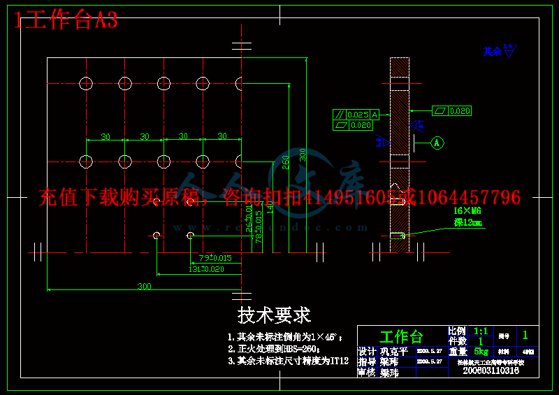
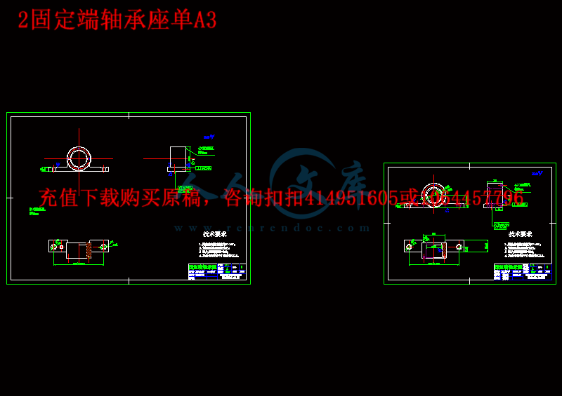
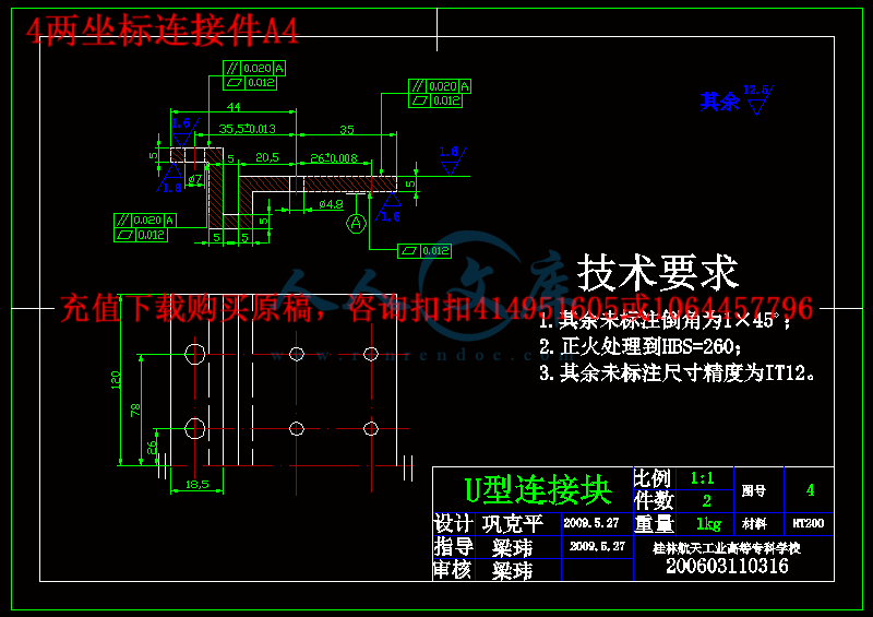
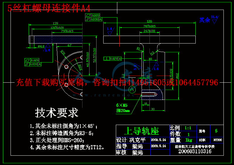
设计过程中主要对工作台的丝杠,导轨,电机,以及升降机的参数进入选择设计,以及工件的联接设计等。同时绘制各主要工件的零件图和工作台装配总图,设计其中重要工件的加工工艺规程。
关键字:工作台 机械设计 激光技术 切割机
ABSTRACT
Laser cutting technology widely used in metal and non-metallic materials processing, can greatly reduce the processing time, lower processing costs and improve the quality of the workpiece. Pulsed laser applied to metal materials. The table for the China Everbright CD-YAG AC200/400/500 laser cutting machine designed. Laser cutting machine in the course of their work can be moved only YY, cutting less than 3 mm thick metal sheets, punching, and so on. Its cutting line directly from CAD drawings transmission, cutting some irregular routes. Since laser cutting for special processing technologies, in the process of cutting no role in cutting edge, the more the design of the table, you can not consider the impact of cutting force. Mechanical systems should have a good servo performance (that is, high-precision, rapid response and stability) to request the transmission mechanism, designed to meet the following: (1) small moment of inertia (2) the stiffness (3) suitable damping Friction also require small (increase the sensitivity), the resonance of good (improve the stability of institutions), the small space (the transmission ensure accuracy), in particular its dynamic characteristics with the servo motor and other links to the dynamic nature of match . The process of designing the main table of the screw, rails, the electrical and lift the parameters into the choice of design, and parts of the link design. At the same time drawing all the major parts of the assembly parts map and the map table, one of the major parts of the design of processing a point of order.
Keywords: table mechanical design laser technology cutting machine
前言
1 激光原理:
激光英文全名为Light Amplification by Stimulated Emission of Radiation (LASER)。 于1960年面世,是一种因刺激产生辐射而强化的光。
科学家在电管中以光或电流的能量来撞击某些晶体或原子易受激发的物质,使其原子的电子达到受激发的高能量状态,当这些电子要回复到平静的低能量状态时,原子就会射出光子,以放出多余的能量;而接着,这些被放出的光子又会撞击其它原子,激发更多的原子产生光子,引发一连串的「连锁反应」,并且都朝同一个方前进,形成强烈而且集中朝向某个方向的光;因此强的激光甚至可用作切割钢板!






 川公网安备: 51019002004831号