目录.wps

闭锁式液力耦合器设计【7张CAD图纸+毕业论文】【答辩优秀】

收藏

压缩包内文档预览:
预览图 预览图
编号:471695    类型:共享资源    大小:1.21MB    格式:RAR    上传时间:2015-08-13 上传人:好资料QQ****51605 IP属地:江苏
45
积分
关 键 词:
闭锁 式液力 耦合器 设计 全套 cad 图纸 毕业论文 答辩 优秀 优良
资源描述:

摘  要

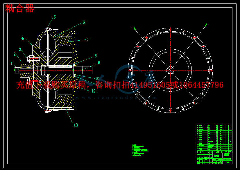
   本次设计的闭锁式液力耦合器可以有效的弥补这方面的缺陷。闭锁式液力耦合器就是在限矩形液力耦合器上加装离心式摩擦离合器组成。其结构使用静压泄液力耦合器的腔型,这样有侧辅腔有足够的空间来放置离心式摩擦离合器而不影响涡轮和泵轮的工作,并采取复合泄液力耦合器的内轮传动式结构。动力通过两路传递:一路以液力传动方式通过外壳~泵轮—涡轮~输出轴,另一路以摩擦离合器方式通过外壳~摩擦离合器~输出轴。随着涡轮转速的升高,摩擦离合器传递的力矩与n成比例的增长,其值在总力矩中的比值也相应增长,当涡轮转速超过某值以后,全部力矩呦摩擦离合器传递,液力传动不再起作用,这时消除了转差损失而成为“直接转动”,传动效率达100%。

关键字:限矩型、静压泄液式、内轮传动、闭锁式、摩擦离合器

ABSTRACT

   The closure of the design of hydraulic coupling can effective type for the defects. Atresia type hydraulic coupling in rectangular hydraulic coupling is limited on centrifugal friction of the clutch. The structure of the static pressure hydraulic coupling use discharge cavity type, so have the auxiliary chamber has enough space to place centrifugal friction clutch and does not affect the turbine and pump wheels work, and take composite relief of hydraulic coupling in wheel drive type structure. Power through the two road transfer: all the way through the shell with hydraulic drive to pump wheels-turbine ~ output shaft, and the other all the way to the friction clutch way through the shell ~ ~ friction clutch output shaft. With the rise of turbine speed, friction clutch transmission torque and n proportional growth, the value of the total torque ratio also corresponding growth, when turbine speed exceeds a certain value after, all round torque friction clutch transmission, hydraulic transmission no longer function, then eliminate the turn and become poor loss "direct turn", the transmission efficiency of 100%.

Key word: limited moment type, static pressure relief liquid type, the inner drive, locking type, friction clutch


前  言1

第一章 液力偶合器的基础知识3

1.1 传动机构及液力传动3

1.2 液力传动的基本原理4

1.3  液力传动的分类4

第二章  液力偶合器的工作原理6

第三章 闭锁式液力偶合器的结构9

3.1  液力偶合器的分类9

3.2  限矩型液力偶合器12

3.2.1  静压泄液式液力偶合器13

3.2.2  动压泄液式液力偶合器14

3.2.3  复合泄液式液力偶合器15

3.2.4  闭锁式液力偶合器17

第四章  闭锁式液力偶合器的参数设计20

4.1  设计原始参数及其分析20

4.1.1  所传功率和转速20

4.1.2  额定转速比与效率20

4.2  工作腔型参数设计及其选择21

4.2.1  液力偶合器有效直径D的确定21

4.2.2  工作腔模型选择及设计22

4.2.3  轮叶设计24

4.2.4  挡板的设计选择26

4.3  轴的设计27

4.3.1  轴上各轴段直径和长度的确定27

4.3.2  强度校核28

4.3.3  刚度校核29

4.3.4  键的选择29

4.3.5  轴承的选择30

4.4  离心式摩擦离合器32

4.4.1  初选摩擦片外径D、内径d、厚度b32

4.4.2  后备系数β32

4.4.3  离合器传递的最大静摩擦力矩Tc33

4.4.4  单位压力P033

4.5  离心块的设计34

4.6 壳体设计和螺栓螺钉选择34

4.6.1  壳体设计34

4.6.2  螺栓螺钉选择与强度计算36

4.7 发热和散热计算38

4.8  辅助系统39

总  结40

致  谢42

参考文献43


前  言

   进入二十一世纪以来,随着我国国民经济的高速发展,我国液力耦合器行业保持了多年高速增长,并随着我国加入WTO, 近年来,液力耦合器行业的出口也形势喜人,2008年,全球金融危机爆发,我国液力耦合器行业发展也遇到了一些困难,如国内需求下降,出口减少等,液力耦合器行业普遍出现了经营不景气和利润下降的局面,2009年,随着我国经济刺激计划出台和全球经济走出低谷,我国液力耦合器行业也逐渐从金融危机的打击中恢复,重新进入良性发展轨道,进入2010年,全球经济复苏的前景面临波折,国内经济结构调整的呼声逐渐升温,贸易保护主义的抬头,液力耦合器行业中技术含量低的人力密集型企业,缺乏品牌的出口导向型企业面临发展危机,而注重培养品牌和技术创新能力较强的企业将占得先机,液力耦合器行业企业如何面对新的经济环境和政策环境,制定适合当前形势和自身特点的发展策略与竞争策略,是液力耦合器行业企业在未来两年我国经济结构调整大潮中立于不败之地的关键,本报告也将从宏观和微观环境对我国液力耦合器行业的发展现状,政策环境、竞争策略,投资前景,市场容量,进出口形势等方面进行全面而权威的分析。

   随着我国加入WTO及全球一体化的深入我国对液力偶合器的应用还不是很普遍,但液力偶合器所具有的改善品质和节约能源等优点,表明了它具有较强的生命力。在许多固定的机械设计上,在动力机与工作机构之间也多设有传动装置,其主要功能不外乎满足工作机调速和调节功率的要求,也有的主要是为了改善起动机加速性能、过载保护、提高运用可靠性和工作寿命。因而传动装置的功用就不仅仅是简单地将动力机之动力传至走行部分,而主要在于将动力机的特性转变为适应车辆运行要求的特征。液力偶合器是一种应用很广泛的通用传动元件,它置于动力机与工作机之间,传递两者的动力。其作用似乎和联轴器相同,但实质并不相同。在改善启动性能、过载保护、无级变速、对载荷有自动适应性等方面,液力偶合器的特性是联轴器所没有的。随着我国科学技术的发展,以及人们对液力偶合器的认识不断加深,其应用领域将会日益扩大。在对相关著作的学习、研究中得到更多、更深层的理论知识。

   当前,国际能源日益紧张,人们不得不把注意力放到如何提高能源利用率和节约能源方面来。因此,可以在应用中节约能源的调速型液力偶合器和液力偶合器传动装置得到了迅速发展。由于液力偶合器传动装置结构复杂、技术精密、加工精度高、难度大、利润高,因而西方各大公司竞相研制生产,竞争很激烈。对于有形资产,各行业都有不同之处,需要分别进行探讨。国外对有形资产要比国内更加重视,他们在理论上有很多需要我们借鉴的地方。尤其一提的是,国外对开发成本的研究日趋成熟,值得我们研究并学习。

我国对液力偶合器的应用还不是很普遍,但液力偶合器所具有的改善品质和节约能源等优点,表明了它具有较强的生命力。随着我国科学技术的发展,以及人们对液力偶合器的认识不断加深,其应用领域将会日益扩大。

本次我的毕业设计做的就是液力偶合器,因为自己也是初次接触设计液力偶合器,不足之处希望老师多提宝贵意见。


内容简介:
河南理工大学万方科技学院本科毕业设计( 翻译 ) 1 Torque Converter principles and structure by moment 1) The form of torque converter and characteristics Torque converter fluid as the working medium is a non-rigid torque variable Converter is one type of hydraulic transmission. orque converter has excellent features, automatic adaptive, variable speed, good Good low speed performance and stability, vibration isolation, and no mechanical wear, is the other transmission element Pieces of irreplaceable. After centuries of development, continuous expansion of the application of torque converter Large, from automobiles, engineering machinery to the petroleum, chemical, mining, metallurgy and machinery, and other areas Has been widely used. Torque converter flow field theory, design and manufacturing, real Testing and other research work, in recent years, has also been rapid development.Abroad have Generally the hydraulic transmission for cars, buses, luxury buses, heavy-duty gas Cars, some tractors and construction machinery. The widely used torque converter are the following forms: (1) General Working through three rounds of closed type hydraulic torque converter. Simple structure, starting and low speed vehicles Exercise, the main advantage of the increased torque performance torque converter, shift when the use of torque converter Buffer capacity, high-speed torque converter lock will make full use of efficient mechanical transmission Performance; (2) Multi-wheel torque converter work. Mainly for applications that require high starting torque Construction machinery and vehicles, and the need for more torque converter on the mechanical conditions of work; (3) guide vane torque converter. When the load required for two-way movement, on the dynamic performance With a constant speed or constant force requirements and other special traction characteristics, with a torque converter must be Has an adjustable feedback control functions, and dynamic indicators meet certain Requirements. Main application areas, with special traction requirements of the various military and civil machinery, Such as air refueling hose reel drag around machinery, active and passive two-way movement Constant load test Inspection machinery, large fixed elevator machinery, land or ship based around the mechanical drag of underwater objects Etc.; (4) a brake hydraulic torque converter traction. Towing capacity, while ensuring, Full use of the deceleration torque converter performance. Russia developed a slight Cited a brake hydraulic torque converter. 2) The construction of hydraulic torque converter Torque converter to the liquid as the medium, increased from the engine transmission and Torque. By the rotating torque converter pump and turbine wheel, and stationary Three components, the guide wheel. The pieces of aluminum alloy casting, or stamping and welding steel plate Made. Pump wheel and the torque converter shell into one. Bolted to the flywheel, turbo Through the driven shaft and the transmission system connected to the piece. After all the work round the assembly, the formation of Circular ring of circular cross section body. It has a closed working chamber, the liquid in the cavity Circulation, in which the pump wheel, turbine and guide rollers, and the input shaft, output shaft and shell Associated bodies. Power grasp internal combustion engine, electric motor, etc.) drive the input shaft rotates, the liquid Body turns out from the centrifugal pump, in turn through the turbine, and then return pump idler pulley wheel, Week Re beginning to circulate. Axis of impeller mechanical energy input passed to the liquid. High-speed Liquid drive a turbine nts 河南理工大学万方科技学院本科毕业设计( 翻译 ) 2 rotation, the energy to the output shaft. By the torque converter fluid Interaction of angular momentum and leaves the change of torque transmission.Torque converter Different from the coupling of the main features is that it has a fixed guide wheel.Guide wheel Diversion effect of the liquid so that the torque converter output torque can be higher or lower than the input Torque, which is called torque converter. And moment coefficients with the output speed rises. Torque converter input shaft and output shaft by the fluid between the contact among the components do not work A rigid connection. Torque converter is characterized by: to eliminate shock and vibration, overload Protection performance and good starting performance; the output shaft speed can be greater than or less than the input shaft Speed, the speed difference between the two axes with the size of the different transfer torque; have a good self- Dynamic speed performance, load increases output speed automatic decline, and vice versa automatically increased; Power machine to ensure a stable work area, the basic load transients will not be reflected To the power machine on. Torque converter efficiency in the vicinity of the higher rated operating conditions. Impeller is Torque converter core. The type and arrangement of its location and shape of leaves, Decision on the role of the performance of torque converter. Some have two or more hydraulic torque converter Turbo, idler pulley or pump wheel, so as to get different performance. The most common is being transferred, Single-stage (only one turbine) torque converter. Performance of both converter and coupler Characteristics of integrated-type torque converter as, for example, can be fixed guide wheel can also be with With the rotating impeller torque converter. To torque converter to work properly, to avoid The avoidance of cavitation and ensure heat dissipation, need some auxiliary fuel system supply pressure System and cooling system. 3) The torque converter works Torque converter equipment currently used widely used by the pump wheel, turbine and guide Round consisting of three components of a single-stage two-phase integrated torque converter Lockup. Pump wheel and the vortex Are basin-shaped wheel. Even with the torque converter impeller housing as one of the active device; vortex Wheels suspended in the torque converter, through the splined output shaft connected to a slave device; guide Suspended in the pump wheel and turbine wheel between the axle through one-way clutch and the guide sleeve fixed In the transmission housing. After starting the engine, crankshaft driven pump wheel rotation, the centrifugal force generated by rotation The pump wheel blades along the blade between the working fluid from the inner to the outer edge thrown; this division As a liquid pump with both wheels turn together with the parks sub-circumferential speed, but also toward the vortex Wheel speed of the axial points. The impact of the working fluid turbine blade, turbine and pump drive the direction of wheel rotation Division. Working fluid flow from the turbine speed can be seen as the working liquid for the turbine Sub-surface flow speed of the turbine turn together with the sub-speed synthesis.When the vortex Comparison of hours of wheel speed, the working fluid flowing from the turbine is backward, the impact of the working fluid Front guide wheel blades. Because the guide wheel is limited to one-way clutch can not turn back, So guide wheel blades will guide the working fluid flows back to move forward pump blades, For the pump wheel rotation, so that the torque acting on the turbine increases. As the turbine speed increases, sub speed bigger, when the turbine blade surface flow Points out with the turbine speed and the speed with the velocity of rotation starting points that guide wheel The back of the blade, the torque converter to reach the critical point. When the turbine speed to further nts河南理工大学万方科技学院本科毕业设计( 翻译 ) 3 increase The working solution will impact the back of guide wheel blades. Because one way clutch allows guide Forward together with the pump wheel wheel rotation, so the working fluid, driven along the guide pulley wheel pump Free rotation direction of rotation, the working fluid back to the pump wheel smoothly.When the flow from the turbine Just out of the working fluid exit to roller blade in the same direction, the torque converter does not produce By torsion (where the torque converter fluid coupling condition is called condition) o One-way clutches are commonly used one-way roller clutch and wedge two. When the one-way clutch outer seat within the seat relative to the direction of rotation to an outer Seat and was stuck between the seat refuses to move; when the outside relative to the seat to another seat within A direction of rotation, the outer seat ring can rotate relative to the seat. Passed by the working fluid torque converter torque transmission efficiency than mechanical transmission Rate is low. Set in the torque converter clutch lock, you can high-speed conditions Lock the pump wheel and turbine together to achieve a direct transfer power to enhance the transmission torque converter Dynamic efficiency. Lock the torque converter clutch in front of the turbine, by locking the piston, reducing Vibrating plate and the turbine drive board composition. Automatic locking clutch in the hydraulic control system Under the control of energy at the right time to lock switch. 4) Increasing of the torque converter principle moments General, thevehicle at low speeds, the need to increase the torque, the pump wheel pass Red wizard flow turbine wheel, idler pulley and driven toward the turbine flow again, so Vortex Wheel torque has been increased. As the speed increases, the guide pulley driven flow again The impact of changes in the angle of the turbine, the turbine torque are smaller increase. Finally, the impact of The flow guide wheel guide wheel of the negative impact, one-way rotating guide wheel, no longer played by Add the function of torque. Specifically, before the car started, the turbine speed is 0, the engine through the Torque converter pump housing driven wheel rotation, and the hydraulic oil with a size of Mp of torque, the torque is the torque converter input torque. Hydraulic oil pump Wheel blades, driven to a certain speed toward the edge of the blade on the turbine, on the vortex Round of an impact torque, the torque is the torque converter output torque. This time Turbine stationary andinto the turbine of the hydraulic oil flow along the turbine blade under the edge of the vortex Round the lower edge of a certain speed, along with the exit of the turbine blade under the edge of the same side Guide to the red wheel, also produced a guide wheel on the impact of torque, and along the stationary guide Back into the impeller wheel blades. When the hydraulic oil on the turbine and the guide wheel torque an impact, Turbine and the guide wheel hydraulic oil also produces a torque of equal size and shock direction Mt and opposite reaction torque Ms, where M t the direction of the direction and phase Mp Instead, the direction of Ms and M p the same direction. According to the force balance of the original hydraulic oil Management, available: Mt = Mp + Ms. Since the reaction turbine of the hydraulic oil, torque Mt And the impact of hydraulic oil on the turbine torque, equal and opposite. So we know that Torque converter output torque is numerically equal to the input torque and the guide wheel of the hydraulic And the reaction torque of the oil. Obviously the torque is greater than the input torque, the solution Power converter with increased torque effect. Increasing torque converter output torque Is the stationary part of the guide wheel hydraulic oil circulating the role of torque, Its value depends not only on red wizard from the turbine wheel flow rate, also depends on the solution Flow direction and the angle between nts 河南理工大学万方科技学院本科毕业设计( 翻译 ) 4 the guide wheel blades. When the flow rate is constant, leaves and The larger the angle between flow, reaction torque is also greater, increasing torsion torque converter The greater. This is the torque converter by moment theory. 5) The development of manufacturing methods of torque converter status. The manufacture of hydraulic torque converter, with the form and structure of the torque converter should be Vary together. The manufacture of the impeller can be divided into two categories: assembly Overall casting style. The former impeller inner, outer and gold leaf were used Stamping or milling from the system, then, by welding, riveting way, the three-part group Complete impeller, the method is low cost, single-piece, precision and flow channel The advantages of high surface roughness, but the tooling costs. Which the impeller inner ring, outer ring Film directly from the die casting into one, typically aluminum castings. According to the formation of flow Core of the system of law is different from the work of the whole round of the casting method is divided into core law and Core method, suitable for a curved surface shape of the leaf thickness and not so Manufacturing. According to different materials to form the mold cavity, the work of the casting wheel Can be divided into sand casting and metal casting. Metal type, gypsum core Casting aluminum impeller torque converter production methods to improve casting Surface roughness to ensure dimensional accuracy, and can cast the blade root of the fillet. Implementation of components (such as hydraulic cylinders and hydraulic motors) which isthe pressure of the liquid can be converted to mechanical energy to drive the load for a straight line reciprocating movement or rotational movement. Control components (that is, the various hydraulic valves) in the hydraulic system to control and regulate the pressure of liquid, flow rate and direction. According to the different control functions, hydraulic pressure control valve can be divided into valves, flow control valves and directional control valve. Pressure control valves are divided into benefits flow valve (safety valve), pressure relief valve, sequence valve, pressure relays, etc.; flow control valves including throttle, adjusting the valves, flow diversion valve sets, etc.; directional control valve includes a one-way valve , one-way fluid control valve, shuttle valve, valve and so on. Under the control of different ways, can be divided into the hydraulic valve control switch valve, control valve and set the value of the ratio control valve. Auxiliary components, including fuel tanks, oil filters, tubing and pipe joints, seals, pressure gauge, oil level, such as oil dollars. Hydraulic oil in the hydraulic system is the work of the energy transfer medium, there are a variety of mineral oil, emulsion oil hydraulic molding Hop categories. The role of the hydraulic system is to help humanity work. Mainly by the implementation of components to rotate or pressure into a reciprocating motion. Hydraulic system and hydraulic power control signal is composed of two parts, the signal control of some parts of the hydraulic power used to drive the control valve movement. nts河南理工大学万方科技学院本科毕业设计( 翻译 ) 5 Part of the hydraulic power means that the circuit diagram used to show the different functions of the interrelationship between components. Containing the source of hydraulic pump, hydraulic motor and auxiliary components; hydraulic control part contains a variety of control valves, used to control the flow of oil, pressure and direction; operative or hydraulic cylinder with hydraulic motors, according to the actual requirements of their choice. In the analysis and design of the actual task, the general block diagram shows the actual operation of equi - pment. Hollow arrow indicates the signal flow, while the solid arrows that energy flow. Basic hydraulic circuit of the action sequence - Control components (two four-way valve) and the spring to reset for the implementation of components (double-acting hydraulic cylinder), as well as the extending and retracting the relief valve opened and closed . For the implementation of components and control components, presentations are based on the corresponding circuit diagram symbols, it also introduced ready made circuit diagram symbols. Working principle of the system, you can turn on all circuits to code. If the first implementation of components numbered 0, the control components associated with the identifier is 1. Out with the implementation of components corresponding to the identifier for the even components, then retracting and implementation of components corresponding to the identifier for the odd components. Hydraulic circuit carried out not only to deal with numbers, but also to deal with the actual device ID, in order to detect system failures. DIN ISO1219-2 standard definition of the number of component composition, which includes the following four parts: device ID, circuit ID, component ID and component ID. The entire system if only one device, device number may be omitted. Practice, another way is to code all of the hydraulic system components for numbers at this time, components and component code should be consistent with the list of numbers. This method is particularly applicable to complex hydraulic control system, each control loop are the corresponding number with the system With mechanical transmission, electrical transmission compared to the hydraulic drive has the following advantages: 1, a variety of hydraulic components, can easily and flexibly to layout. 2, light weight, small size, small inertia, fast response. 3, to facilitate manipulation of control, enabling a wide range of stepless speed regulation (speed range of 2000:1). 4, to achieve overload protection automatically. nts 河南理工大学万方科技学院本科毕业设计( 翻译 ) 6 5, the general use of mineral oil as a working medium, the relative motion can be self-lubricating surface, long service life; 6, it is easy to achieve linear motion / 7, it is easy to achieve the automation of machines, when the joint control of the use of electro-hydraulic, not only can achieve a higher degree of process automation, and remote
温馨提示:
1: 本站所有资源如无特殊说明,都需要本地电脑安装OFFICE2007和PDF阅读器。图纸软件为CAD,CAXA,PROE,UG,SolidWorks等.压缩文件请下载最新的WinRAR软件解压。
2: 本站的文档不包含任何第三方提供的附件图纸等,如果需要附件,请联系上传者。文件的所有权益归上传用户所有。
3.本站RAR压缩包中若带图纸,网页内容里面会有图纸预览,若没有图纸预览就没有图纸。
4. 未经权益所有人同意不得将文件中的内容挪作商业或盈利用途。
5. 人人文库网仅提供信息存储空间,仅对用户上传内容的表现方式做保护处理,对用户上传分享的文档内容本身不做任何修改或编辑,并不能对任何下载内容负责。
6. 下载文件中如有侵权或不适当内容,请与我们联系,我们立即纠正。
7. 本站不保证下载资源的准确性、安全性和完整性, 同时也不承担用户因使用这些下载资源对自己和他人造成任何形式的伤害或损失。
提示  人人文库网所有资源均是用户自行上传分享,仅供网友学习交流,未经上传用户书面授权,请勿作他用。
关于本文
本文标题:闭锁式液力耦合器设计【7张CAD图纸+毕业论文】【答辩优秀】
链接地址:https://www.renrendoc.com/p-471695.html

官方联系方式

2:不支持迅雷下载,请使用浏览器下载   
3:不支持QQ浏览器下载,请用其他浏览器   
4:下载后的文档和图纸-无水印   
5:文档经过压缩,下载后原文更清晰   
关于我们 - 网站声明 - 网站地图 - 资源地图 - 友情链接 - 网站客服 - 联系我们

网站客服QQ:2881952447     

copyright@ 2020-2025  renrendoc.com 人人文库版权所有   联系电话:400-852-1180

备案号:蜀ICP备2022000484号-2       经营许可证: 川B2-20220663       公网安备川公网安备: 51019002004831号

本站为文档C2C交易模式,即用户上传的文档直接被用户下载,本站只是中间服务平台,本站所有文档下载所得的收益归上传人(含作者)所有。人人文库网仅提供信息存储空间,仅对用户上传内容的表现方式做保护处理,对上载内容本身不做任何修改或编辑。若文档所含内容侵犯了您的版权或隐私,请立即通知人人文库网,我们立即给予删除!