翻译原文-6-2.doc

发动机配件生产线多工位工作台设计【20张CAD图纸+毕业论文】【答辩优秀】

收藏

资源目录
跳过导航链接。
发动机配件生产线多工位工作台设计【全套CAD图纸+毕业论文】【答辩优秀】.rar
英语翻译-6-2.doc---(点击预览)
翻译原文-6-2.doc---(点击预览)
毕业设计说明书.docx---(点击预览)
任务书.doc---(点击预览)
2014年毕业设计(论文)开题报告(最终).doc---(点击预览)
2014年机电工程学院毕业设计(论文)进度计划表.doc---(点击预览)
PDF 文本
图纸CAXA
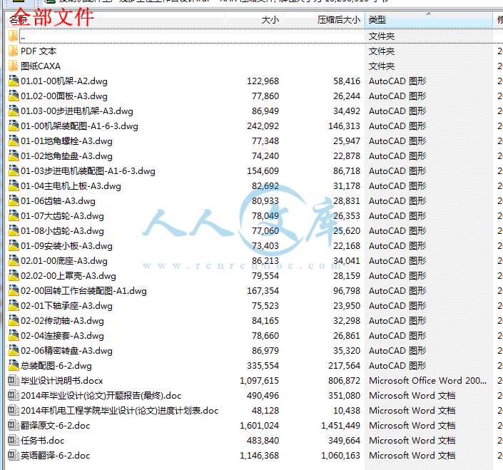
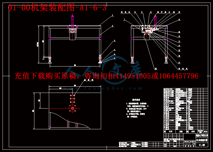
01-00机架装配图-A1-6-3.exb
01-01地角螺栓-A3.exb
01-02地角垫盘-A3.exb
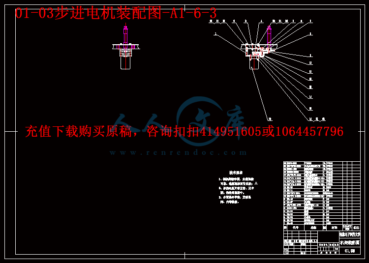
01-03步进电机装配图-A1-6-3.exb
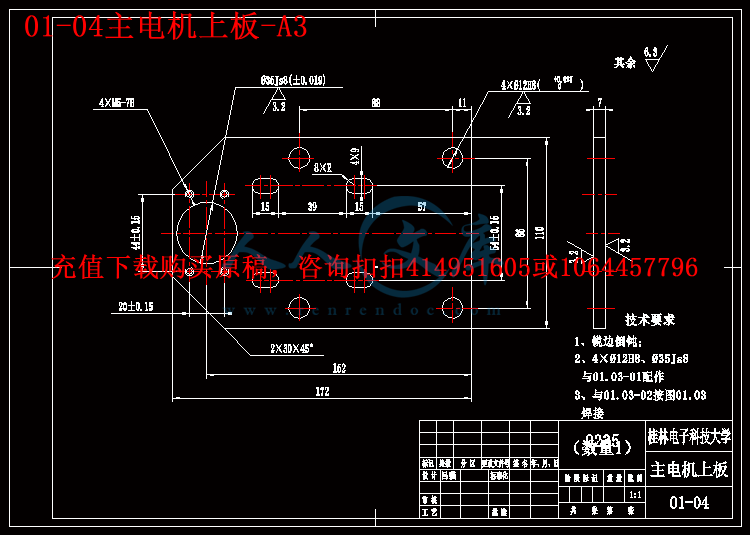
01-04主电机上板-A3.exb
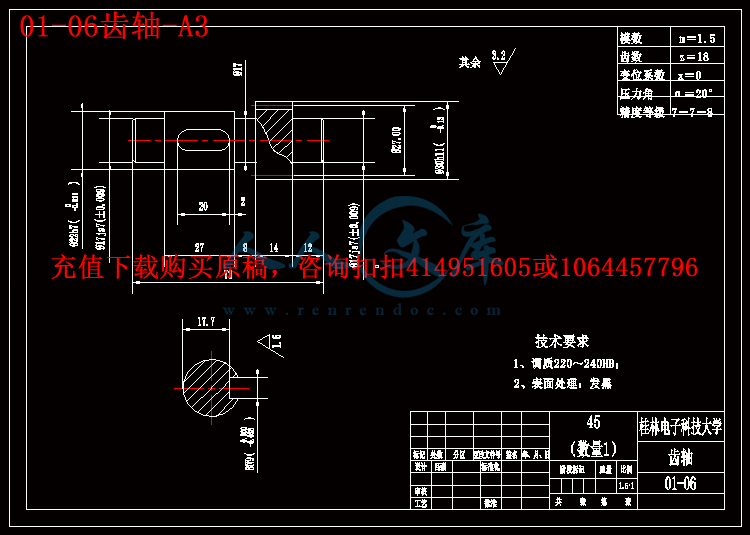
01-06齿轴-A3.exb
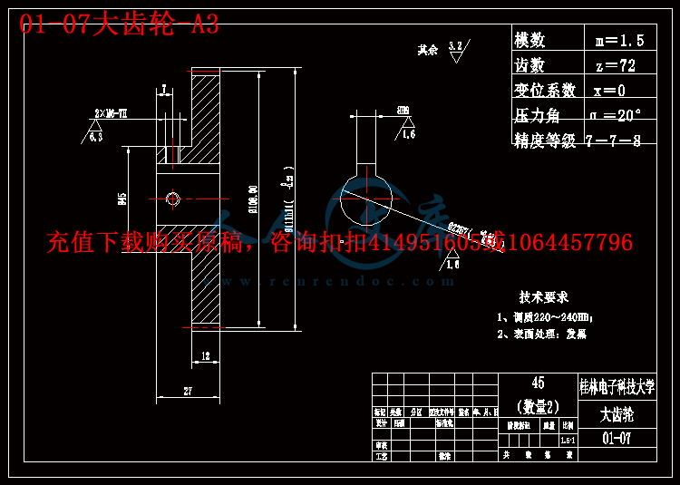
01-07大齿轮-A3.exb
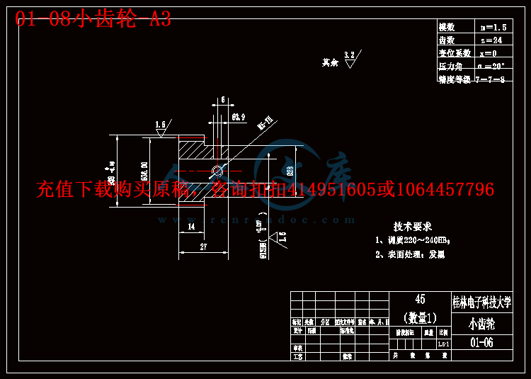
01-08小齿轮-A3.exb
01-09安装小板-A3.exb
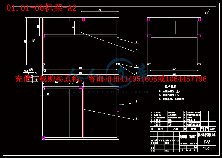
01.01-00机架-A2.exb
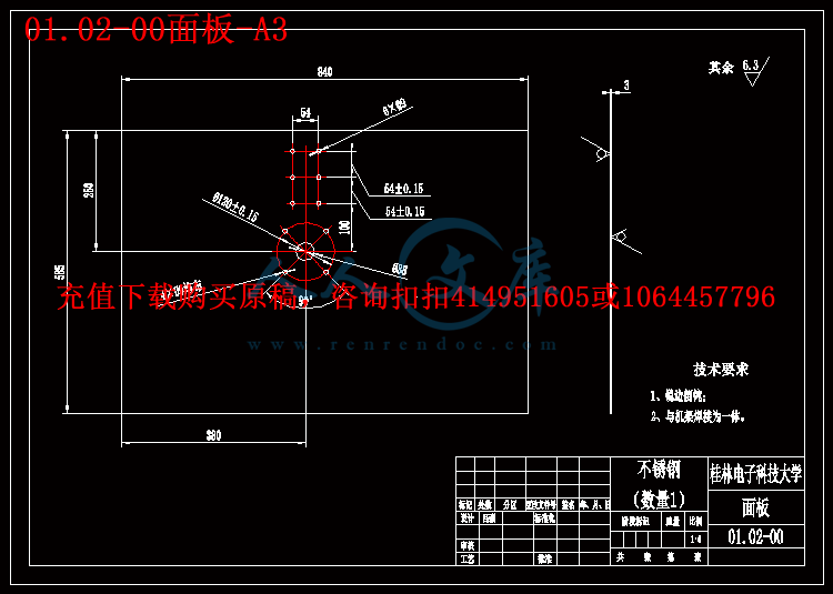
01.02-00面板-A3.exb
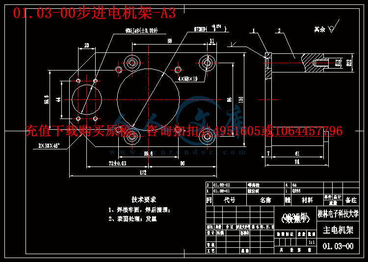
01.03-00步进电机架-A3.exb
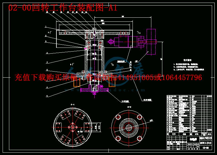
02-00回转工作台装配图-A1.exb
02-01下轴承座-A3.exb
02-02传动轴-A3.exb
02-04连接套-A3.exb
02-06精密转盘-A3.exb
02.01-00底座-A3.exb
02.02-00上罩壳-A3.exb
总装配图-6-2.exb
01-00机架装配图-A1-6-3.dwg
01-01地角螺栓-A3.dwg
01-02地角垫盘-A3.dwg
01-03步进电机装配图-A1-6-3.dwg
01-04主电机上板-A3.dwg
01-06齿轴-A3.dwg
01-07大齿轮-A3.dwg
01-08小齿轮-A3.dwg
01-09安装小板-A3.dwg
01.01-00机架-A2.dwg
01.02-00面板-A3.dwg
01.03-00步进电机架-A3.dwg
02-00回转工作台装配图-A1.dwg
02-01下轴承座-A3.dwg
02-02传动轴-A3.dwg
02-04连接套-A3.dwg
02-06精密转盘-A3.dwg
02.01-00底座-A3.dwg
02.02-00上罩壳-A3.dwg
总装配图-6-2.dwg
压缩包内文档预览:(预览前20页/共31页)
预览图 预览图 预览图 预览图 预览图 预览图 预览图 预览图 预览图 预览图 预览图 预览图 预览图 预览图 预览图 预览图 预览图 预览图 预览图 预览图
编号:472006    类型:共享资源    大小:8.74MB    格式:RAR    上传时间:2015-08-13 上传人:好资料QQ****51605 IP属地:江苏
45
积分
关 键 词:
发动机配件 生产线 多工位 工作台 设计 全套 cad 图纸 毕业论文 答辩 优秀 优良
资源描述:

摘  要


本毕业设计是根据企业指定产品的加工需求,来设计一种与生产线匹配,符合加工技术要求的六工位工作台。本设计主要内容是选择并设计相应的机构,对多工位工作台作总体布局设计,编制工作循环图。该工作台主要任务是要完成工件的上料、注液涂敷、吹干、下料等六道工序,吹干过程占用了三道工序。本设计要求单件工件生产周期为12s,工艺加工的时间不低于2s。该六工位回转工作台采用通过控制步进电机停动的方法来实现工作台的转位和定位,通过控制输入电脉冲的数量和频率来实现工作台的角位移与转速,由步进电机带动转盘来移动工件,将工件夹持转动到相应的工位进行加工。而步进电机本身就带有很好的自锁的功能,对工件进行加工的期间转盘就不会发生转动,保证整个加工过程中定位准确,从而使整个工件加工的质量更好。

关键词:六工位回转工作台;步进电机;定位;自锁;


Abstract


The graduation project base on the demand for the product processing enterprises designs a six processing stations workbench which designated to match the design of a production line and fit the technical requirement. The design of the main content is to select and design the appropriate agency, design a multi-position bench for the overall layout and draw the cycle diagram. The main task is to complete draw up the material on table of the work-piece, injection fluid coating, drying, cutting and other six processes, drying process takes three processes. The design requirements for cycle of single-piece production is 12s, craft processing time is not less than 2s. The six-station rotary table with stepper motor by controlling the stopping method to achieve transposition table and positioning, by controlling the input number and frequency of electrical pulses to achieve the angular displacement and speed table, by a stepping motor drive wheel to move the work-piece, the work-piece holder is rotated to the corresponding processing station. Because the stepper motor itself has a good self-locking function during machining of the work-piece, so the turntable occur rotated to ensure accurate positioning during the entire process, and so the process for the work-piece has a better quality.

Keyword: Six-station rotary table; Stepper motors; positioning; self-locking;


目    录


1  绪论1

1.1 回转工作台的研究背景及意义1

1.2 回转工作台的历史、现状及应用1

1.3 课题的主要任务3

2  总体方案设计3

2.1 原理方案的设计3

2.2 动力的选择5

2.3动力传动方式的选择5

2.4轴承的选用7

3  计算分析8

3.1工作台回转运动规律分析8

3.2步进电机启动力矩的计算9

3.3直齿圆柱齿轮的传动设计10

3.3.1、选定齿轮类型、精度等级、材料及齿数10

3.3.2、按齿面接触强度设计10

3.3.3、根据齿根弯曲强度计算11

3.3.4、齿轮几何尺寸13

3.3.5、齿轮验算13

3.3.6、齿轮结构设计尺寸13

3.3.7、第二对齿轮的设计15

3.4支撑轴的设计计算17

3.4.1、选择轴的材料和热处理17

3.4.2、初步估算轴的直径17

3.4.3、轴的结构设计17

3.5滚动轴承的计算分析23

4  其他结构的设计24

4.1 精密转盘的设计24

4.2底座的设计25

4.3机架的设计25

4.3.1  机架设计的准则25

4.3.2 机架设计的要求26

4.3.3机架材料的选择26

4.3.4 机架结构的设计27

5  结论28

谢  辞29

参考文献30


1  绪论

1.1 回转工作台的研究背景及意义

随着我国现代化工业技术的迅速发展,特别是随着回转工作台在自动化领域内的迅速发展,回转工作台组合机床的研究已经成为当今机械制造行业的一个重要方向,在现代工业运用中,大多数机械的设计和制造都是用机床大批量完成的。现代大型工业技术的飞快发展,降低了回转工作台组合机床的实现成本,软件支持机械也使得实现变得更为简单,因此,研究回转工作台组合机床的设计具有非常重要的理论意义及现实意义。  

在工业快速发展的现代化浪潮中,各种机械设计和制造业中,回转工作台组合机床的应用越来越广泛,越来越转化为生产力,从这个意义上讲,对回转工作台组合机床的研究具有重要的现实意义。回转工作台组合机床是根据工件加工需要,以通用部件为基础,配以少量专用部件组成的一种高效专用机床。回转工作台组合机床是按系列化标准化设计的通用部件和按被加工零件的形状及加工工艺要求设计的专用部件组成的专用机床。由于通用部件已经标准化和系列化,可根据需要灵活配置,从而缩短了设计和制造的周期,因此,回转工作台组合机床兼有低成本和高效率的优点,在大批、大量生产中得到了广泛的应用,并可用以组成自动生产线[6]。

回转工作台是组合机床的一种输送部件,它将被加工工件从一个工位转换到另一个工位。常常一个工位用作装夹工件,而其他几个工位同时对工件进行加工,因此,机床的生产率较高,一台组合机床相当于一条圆形自动线,而且占地面积较小,其结构比自动线简单。多工位回转工作台适合复杂机械零件流水作业的加工需求,具有运行平稳、高效率高等特点。与自动线相比多工位回转工作台具有诸多的优点。其应用范围不断扩展。多工位回转工作台式机床同时具备柔性、生产率和精密的特点并能提供高度的技术效能技术与精巧的机械设备想结合使其能高效加工某零件族。零件的整个加工过程越来越多地是用单一零件夹具进行的。与在若干台机床上加工的“老式”加工方法相比这不仅简化了生产的后勤工作而且大大地提高了加工精度。特别是当零件在不同加工平面和不同的加工轴之间具有相互制约的公差时。集成有若干个加工工位的多工位回转工作台式机床更具特别优势[11]。

内容简介:
编号: 毕业设计 (论文 )外文翻译 (原文) 题 目: Dynamic load analysis and Design methodology of LCD transfer robot 院 (系): 机电工程学院 专 业: 机械设计制造及其自动化 学生姓名: 吕 强 学 号: 1000110125 指导教师单位: 机电工程学院 姓 名: 唐 焱 职 称: 副教授 题目类型 : 理论研究 实验研究 工程设计 工程技术研究 软件开发 2014 年 5 月 25 日 ntsDynamic load analysis and design methodology of LCD transfer robot Jong Hwi Seo1, Hong Jae Yim2,*, Jae Chul Hwang1, Yong Won Choi1 and Dong Il Kim 1 1Robotics Technology Lab, Mechatronics & Manufacturing Technology Center SAMSUNG Electronics Co., LTD. Suwon, South Korea 2School of Mechanical and Manufacturing Engineering, Kookmin University SeongBuk-Gu, Seoul, South Korea (Manuscript Received July 20, 2007; Revised December 28, 2007; Accepted January 16, 2008) Abstract The objective of the present study is to develop a design methodology for the large scale heavy duty robot to meet the design requirements of vibration and stress levels in structural components resulting from exposure of system modules to LCD (Liquid Crystal Display) processing environments. Vibrations of the component structures significantly influence the motion accuracy and fatigue damage. To analyze and design a heavy duty robot for LCD transfer, FE and multi-body dynamic simulation techniques have been used. The links of a robot are modeled as flexible bodies using modal coordinates. Nonlinear mechanical properties such as friction, compliance of reducers and bearings were considered in the flexible multi-body dynamics model. Various design proposals are investigated to improve structural design performances by using the dynamic simulation model. Design sensitivity analyses with respect to vibration and stresses are carried out to search an optimal design. An example of an 8G (8th-Generation) LTR (LCD Transfer Robot) is illustrated to demonstrate the proposed methodology. Finally, the results are verified by real experiments including vibration testing. Keywords: Flexible multibody dynamics; LTR (LCD Transfer Robot); Vibration fatigue 1. Introduction ntsLCDs are widely used in TVs, computers, mobile phones, etc., because they offer some real advantages over other display technologies. They are thinner and lighter and draw much less power. Recently, the size of raw glass has greatly increased in new generation LCD (Liquid Crystal Display) technology. In order to handle bigger and heavier glasses, it is necessary to develop a large scale LTR (LCD transfer robot) to support various complicated LCD fabrication processes.It will cause many difficult design problems such as vibration, handling accuracy deterioration and high stresses due to heavier dynamic loads, resulting in inaccurate transfer motion and fatigue cracks. Therefore, it is necessary to establish a methodology for predicting deflections, vibrations, and dynamic stress time histories using virtual computer simulation models. An integrated design simulation method would be useful to validate a baseline design and to propose new improved designs. In this paper an integrated computer simulation methodology is presented to predict deflections, dynamic stresses due to vibrations design, based on the existing FEM and flexible body dynamics technology. The proposed methodology is applied to the LTR that handles 7G/8G LCD glasses. Vibration analysis is performed and validated with the vibration modal test to identify and to recapture the inherent phenomenon in the system. Some flexible components in the LTR may experience severe vibration to cause fatigue damage due to large dynamic loads. Modal characteristics are used to consider structural flexibility in flexible multi-body dynamic simulations. Tip deflection of the end-effecter can be calculated to see if design requirements are met. Dynamic loads and dynamic stress histories can be obtained from the dynamic simulation. Stress levels are investigated at the critical areas to predict if fatigue cracks might occur. If the stress level is not in a safe region, design change should be made based on the computer simulation results and design sensitivity study. Then a prototype LTR is built and tested for design validation.The present paper describes the CAE-based durability analysis that is being implemented and developed at SAMSUNG, to predict fatigue damage corresponding to durability tests. The proposed methodology can be used to develop a new large scale LTR robot in the early design stage. 2. Introduction of LCD-transfer robot Fig. 1 shows various types of LTRs. Telescope type LTR consists of a base frame, an R-frame, two Z-frames, two articulated arms with slender hands as shown in Fig. 1(a). The frame structures are fabricated with cast iron and aluminium. Hands with slender fingers are made of lightweight composite materials.It also has two arms (upper and lower arms) to handle two glasses simultaneously. The LTR has a cylindrical workspace to transfer glasses for various fabrication processes. For precision control of handling the glasses, static ntsdeformation at the tip of the finger must be less than 10 mm. Since the joints which connect the arms and links include bearings and reducers, joint compliance must be considered to predict the static deformation at the tip. Flexibilities of the arm itself are also important to both static and dynamic deformation, because the arm is a kind of cantilever type structure with a large lumped mass at the tip. LTR is supposed to repeat millions of cycles to perform LCD fabrication processes in real life. Therefore, it has to pass physical tests to ensure the survivability of the robot system when subjected to static and cyclic loadings. The durability test involves a cyclic loading apparatus that evaluates the durability characteristics of the component structure. Among the many different tests, one of the most critical is the hand motion of stretching out and pulling in with the zframes vertical motion. The critical motion simulates the jerking and twisting impact that an arm support bracket might experience when running with large glasses loaded. The arms and hands are synchronized and moved at a speed of about 4 m/s. (a) Telescopic type nts (b) Gate type (c) Link type Fig. 1. LCD Transfer robots (LTR). Since the LTR repeats millions of cycles of particular loading and unloading with various configurations,it may result in fatigue failure at a critical stress area.In this paper, to predict static and dynamic deformation at the tip of the finger and critical stress levels including vibration of the LTR, flexible multi-body dynamic simulations are presented. Link-frames,arms are modelled as flexible bodies. Static and dynamic deformation is assumed to be very small, therefore,within the linear elastic range. To represent the flexibility, vibration normal modes and static correction modes are obtained from the finite element vibration and static analysis for each flexible component.To represent the joint compliance, spring and damper force elements are used instead of kinematic joint elements 1. nts3. Flexible multi-body dynamics The main advantage of using modal coordinates in flexible multi-body dynamics is the reduction in the number of generalized coordinates that must be included in the analysis. Two types of modes are used in component mode synthesis for flexible multi-body dynamics 1, 2. One is a normal mode. The other is a static mode. All used normal modes and static modes must be normalized to have the same magnitude and be orthogonalized to be independent to each other. 3.1 Kinematics of flexible components A typical flexible component is shown in Fig. 2. The flexible component i is discretized into a large number of finite elements. The global position of a point p in a flexible part i can be represented as Where is the global position vector of the X-Y-Z body reference frame, is the coordinate transformation matrix from the body reference frame to the global inertial frame, is the initial position vector of the point p from the body reference frame, and is the displacement vector due to deformation.The displacement vector can be approximated by a linear combination of deformation modes like Eq. (2). Where is a modal matrix and is the corresponding deformation mode of a flexible part i. is a 6N1 modalvector and is modal coordinates, M is the number of modal coordinates. The deformation modes can be normal modes, static modes, or combination of normal and static modes. Used M modes should be linearly independent to each other. 3.2 Flexible multi-body dynamic equations As shown in Fig. 2, the nodal position vector of a typical point p in the global reference frame can thus be written as Eq. (3) by using Eq. (2) Where and the rotational displacementi of nodal point p is defined by . The combined set of kinematic and driving constraints of the multi-body dynamic system may be written in the form 3, 4 nts Where the generalized coordinates , t is the time, is the constraint equation. Using the Lagrange Multiplier Theorem, variational equations of motion of the multi-body system may be obtained by summing all bodies and constraints in the system as in the matrix form of Eq. This is a mixed system of differential-algebraic equations of motion for considering the elastic effect of the mechanical system. To solve mixed differential algebraic equations, many numerical algorithms have been developed 3. Using Eq. (5), dynamic stress history of a flexible component can be calculated 5. 4. Dynamic modelling of an lcd-transfer robot The 8G-Telescopic type LTR system shown in Fig. Fig. 3. Flexible multi-body dynamics model for 8G-Telescopic LTR. nts Fig. 4. Dynamic modeling of LTR arm system 1(a) can be modeled with 86 rigid bodies, 30 flexible bodies, kinematic joints, and force elements 3. The flexible bodies considered in the multi-body dynamic simulation are named in the Fig. 1(a). Fig. 3 shows the flexible multi-body simulation model for 8GTelescopic LTR. For parallel rectilinear motion of the finger and hand-bracket, a timing belt at each arm system is modeled to drive at constant speed ratio. As shown in Fig. 4, to represent the elasticity and damping of the belt, spring and damping forces are approximated to be proportional to displacement and velocity of the belt length change. Even the joint compliances for bearing and reducers are modeled in a similar way with rotational-spring and damper elements. The experimental values from the components makers are shown in Table nts1. Major components such as arms and link frames are made of cast iron or cast aluminium. Those structural components can be assumed to be linear elastic during normal operation. However, such a small elastic deformation may cause vibration and repeated dynamic stresses resulting in inaccurate transfer motion and fatigue cracks. Therefore, it is necessary to establish a methodology for predicting the deformation, vibration, and dynamic stress time histories with a virtual computer simulation model. Component mode synthesis technique 1-4, explained in the previous section, can be used for efficient computer simulation in large rigid body gross motion with small elastic deformation. Since the component mode synthesis method employs modal coordinates to consider the elastic deformation of flexible bodies, it is possible to execute a large multibody dynamic system analysis more effectively by using a small number of well-selected modes. Fig. 5 shows the 1st vibration modes of flexible components in the telescopic LTR in Fig. 1(a). Also,Fig. 5 shows a typical component mode and the number of modes used in the mode component synthesis method for the flexible multi-body dynamic analysis. Table 1. Joint stiffness for bearing and reducers. No Axial Stiffness Radial Stiffness Part 1 180 KNm/rad 2570 KNm/rad Reducer 2 250 KNm/rad 3510 KNm/rad Reducer 3 67 KNm/rad 1000 KNm/rad Reducer 4 6745 KNm/rad 43840 KNm/rad Reducer 5 0 436360 KNm/rad Bearing (a) Finger (36) (c) Arm-Frame (42) (d) Z1-Frame (24) nts (e) Z2-Frame (24) (f) R-Frame (36) Fig. 5. Component modes of flexible bodies (number of modes used for dynamic simulation). 5. Analysis and design improvement of LTR 5.1. Modal analysis of 8G-telescopic LTR Since major structural bodies such as arms and link-frames are modelled as flexible bodies, the proper kinematic joints and force elements, fundamental vibration modes of the total LTR system can be investigated. The modes calculated from the vibration analysis can be used for searching for the structural weak point and used for the flexible multi-body dynamic simulation explained in the previous chapter. Fig. 6 shows the modal deformation from the vibration test of the LTR system. Analytical vibration modes calculated from the dynamic simulation model are compared with the experimental test results for validation. Comparison with the modal test results showed that simulation results correlate well with the test results. From the results of the analytical and experimental modal deformation, we found that the structural weak point was the R-frame. This information was very important to reduce the system vibration,as explained in the following section. 5.2 Vibration analysis and design improvement Design problems such as tip deflection and fatigue crack can be investigated with a valid simulation model. Among the various process events for LCD glass transfer motion, stretching out and pulling in motions of the hands with glass loaded are the most critical motions to cause severe vibration and high stresses at the supporting bracket structure. Using the proposed flexible multi-body simulation technology, the critical motion is regenerated to investigate how large deflection and stresses occur during the operation. Since we have a valid simulation model, we can investigate various design proposals.After the prototype robot ntswas developed, undesirable vibration at the measure point was observed when the robot was running onto the guide rail, as shown in Fig. 7. The cause of the vibration was the insufficient stiffness of the R-frame, studying from the analysis of the system modal deformation, as explained in the previous section. In other words, the Rframe at the base of the LTR was known to be a critical component for the vibration. To increase bending and twisting stiffness, height and width of the beam cross section was enlarged,and ribs were added as explained in the Fig. 7. Even aluminium material is replaced with high strength steel to increase the elastic modulus. To verify the design modification, a dynamic simulation model was used. Fig. 6. Vibration modes by experiment and comparison of frequencies nts Fig. 7. Design study to reduce the vibration by dynamics simulation. Fig. 8. Comparison of vibration levels between the original and modified design. nts Fig. 9. An example of the crack fatigue. Fig. 8 shows a comparison of vibration displacements during the simulated motions between the original baseline design and the new improved design. More than 50% reduction of the vibration level is observed during the critical motion period from 5 to 10 seconds even at the prototype test as shown in Fig. 8. 5.3 Stress analysis and design improvement As the size of raw glass tends to become larger for productivity and manufacturing cost competitiveness,LTR robots need to be faster and bigger to handle the larger and heavier glasses with higher speed. This may result in increased dynamic loads causing fatigue cracks due to dynamic stresses. ntsFig. 9 shows an example of the fatigue cracks due to dynamic loads at the supporting arm-frame structure in the 7G-Gate LTR shown in Fig. 1(b). Using the flexible multi-body dynamic simulation, cause and effect for the fatigue crack can be analyzed prior to adoption in an actual spot. To reduce the level of dynamic stress at the critical area, the shape and thickness of the structure must be redesigned based on the validated simulation model. Experimental tests were executed to validate the accuracy of dynamic stresses predicted in virtual computer simulations, as shown in Fig. 10. And the result was exactly the same as the point of occurrence of the crack. Fig. 11 shows the design modification. To reduce the stress concentration, the rectangular shape with sharp corners was changed to a round shape, and ribs were changed. Fig. 12 shows a comparison of maximum dynamic stresses between the modified shape and original shape with different metal thickness. The stress measure point of the part is the dotted circle area in the Fig. 10. This result shows the conclusion that the design was reasonably modified. Practically, the modified design was adopted for the 7G-Gate LTR in the actual spot. nts Fig. 10. Strain experiment and dynamic analysis for fatigue life prediction. Fig. 11. Design modification for avoiding stress concentration. ntsFig. 12. Stress analysis and design improvement 5.4 Handling accuracy and design optimization If dynamic loads are increased, it might deteriorate the accuracy of the precision transfer motion due to deflection and deformation of major structural components 6. Fig. 13 shows the vertical deflections at the tip points of the fingers for the baseline design of the 8G-Telecscopic LTR.The tip deflection of the original design of the LTR was 42 mm. This exceeds the design specification requirement of 10 mm for the LCD fabrication process, and may be the cause of the collision between cassette and robot hands. The cause of the deflection was that the robot structure was very large and heavy. As a result, the deflection must be reduced and the transfer accuracy improved by using the dynamic simulation and optimized design techniques. To reduce the dynamic deflection, a thin-tapered circular plate, what we called a liner, was used, as shown in Fig. 14. The combination of the three line
温馨提示:
1: 本站所有资源如无特殊说明,都需要本地电脑安装OFFICE2007和PDF阅读器。图纸软件为CAD,CAXA,PROE,UG,SolidWorks等.压缩文件请下载最新的WinRAR软件解压。
2: 本站的文档不包含任何第三方提供的附件图纸等,如果需要附件,请联系上传者。文件的所有权益归上传用户所有。
3.本站RAR压缩包中若带图纸,网页内容里面会有图纸预览,若没有图纸预览就没有图纸。
4. 未经权益所有人同意不得将文件中的内容挪作商业或盈利用途。
5. 人人文库网仅提供信息存储空间,仅对用户上传内容的表现方式做保护处理,对用户上传分享的文档内容本身不做任何修改或编辑,并不能对任何下载内容负责。
6. 下载文件中如有侵权或不适当内容,请与我们联系,我们立即纠正。
7. 本站不保证下载资源的准确性、安全性和完整性, 同时也不承担用户因使用这些下载资源对自己和他人造成任何形式的伤害或损失。
提示  人人文库网所有资源均是用户自行上传分享,仅供网友学习交流,未经上传用户书面授权,请勿作他用。
关于本文
本文标题:发动机配件生产线多工位工作台设计【20张CAD图纸+毕业论文】【答辩优秀】
链接地址:https://www.renrendoc.com/p-472006.html

官方联系方式

2:不支持迅雷下载,请使用浏览器下载   
3:不支持QQ浏览器下载,请用其他浏览器   
4:下载后的文档和图纸-无水印   
5:文档经过压缩,下载后原文更清晰   
关于我们 - 网站声明 - 网站地图 - 资源地图 - 友情链接 - 网站客服 - 联系我们

网站客服QQ:2881952447     

copyright@ 2020-2025  renrendoc.com 人人文库版权所有   联系电话:400-852-1180

备案号:蜀ICP备2022000484号-2       经营许可证: 川B2-20220663       公网安备川公网安备: 51019002004831号

本站为文档C2C交易模式,即用户上传的文档直接被用户下载,本站只是中间服务平台,本站所有文档下载所得的收益归上传人(含作者)所有。人人文库网仅提供信息存储空间,仅对用户上传内容的表现方式做保护处理,对上载内容本身不做任何修改或编辑。若文档所含内容侵犯了您的版权或隐私,请立即通知人人文库网,我们立即给予删除!