设计说明书.docx

小功率机械摩擦式无级变速器结构设计说明书【7张CAD图纸+毕业论文】【答辩优秀】

收藏

资源目录
跳过导航链接。
小功率机械摩擦式无级变速器结构设计说明书【全套CAD图纸+毕业论文】【答辩优秀】.rar
小功率机械摩擦式无级变速器结构设计说明书
设计说明书.docx---(点击预览)
外文文献.pdf---(点击预览)
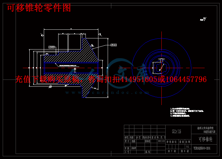
可移锥轮零件图.dwg
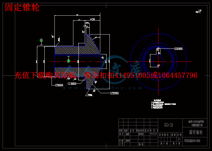
固定锥轮.dwg
装配图.dwg
调节套.dwg
轴.dwg
轴承套.dwg
钢环.dwg
压缩包内文档预览:(预览前20页/共38页)
预览图 预览图 预览图 预览图 预览图 预览图 预览图 预览图 预览图 预览图 预览图 预览图 预览图 预览图 预览图 预览图 预览图 预览图 预览图 预览图
编号:473075    类型:共享资源    大小:2.34MB    格式:RAR    上传时间:2015-08-17 上传人:好资料QQ****51605 IP属地:江苏
45
积分
关 键 词:
功率 机械 摩擦 磨擦 无级 变速器 结构设计 说明书 仿单 全套 cad 图纸 毕业论文 答辩 优秀 优良
资源描述:

目  录


摘要7

Abstract:8

第一章  绪论9

§1.2  机械无级变速器的特征和应用10

§1.3机械无级变速器的选用和润滑密封12

§1.4 本文的主要内容及要求14

第二章摩擦无级变速器的机械特性加压装置和调速机构15

§2.1  机械特性15

§2.2  调速操纵机构16

§2.3  加压装置17

第三章摩擦式无级变速器设计说明和计算过程18

§3.1  摩擦机械无级变速器的工作原理18

§3.2  摩擦无级变速器的特点19

§3.3  锥轮的设计与计算19

§3.4  钢环的设计与计算23

1、钢环尺寸和参数的确定23

2、强度验算25

§3.5  轴系的设计26

§3.6  轴的结构设计27

第四章   主要零件的校核29

§4.1 .输出,输入轴的校核29

§4.2 . 轴承的校核30

总 结  31

致 谢  32

参考文献资料33


摩擦式机械无级变速器结构设计

摘要

在某种控制的作用下,使机器的输出轴转速可在两个极值范围内连续变化的无级变速器传动随着机械、材质及加工工艺的高速发展和其需求量日益增多而得到广泛应用和发展。无级变速器的主动和从动两根轴通过传递转矩的中间介质(机械构件、流体、电磁流等)把两根轴直接或间接地联系起来并传递动力。当对主、从动轴的联系关系进行控制时,则两轴间的传动比发生变化(在两极值范围内连续而任意地变化)。用机械构件作为中间介质的为机械无级变速器,其包括摩擦式和脉动式。无级变速器与定传动比传动及有级变速传动(它只有有限的几种传动比)相比,其优点是能够根据工作需要在一定范围内连续变换速度,以适应输出转速和外界负载变化的要求,摩擦式机械无级变速器依靠传动元件之间的摩擦进行传动,钢材材质、加工工艺水平和润滑油料品质等因素是摩擦式机械式无级变速器不断发展的重要保证。本文通过查阅相关的诸多文献和书籍手册等进行钢环式无级变速器原理及其结构、变速原理的传动结构的实现的研究,并对摩擦式机械无级变速器进行结构设计,可直接作为设计文件或指导文件进行生产加工。


关键词:无级变速器;摩擦式;传动;润滑;


The structure design of CVT machine of friction type

Abstract:

Under the action of some kind of control which can make the output of the machine spindle speed in two extreme CVT within the framework of the continuous variation of the transmission with the high-speed development of machinery, materials and processing technology and its demand is growing and is widely used and CVT transmission of the driving and driven by passing two shaft torque in the middle of the medium (mechanical components, fluid, electromagnetic flow, etc.), the two shaft linked directly or indirectly, and transfer power.When were related to the Lord, driven shaft to control, is the ratio between the two axis change (within the scope of the two extreme consecutive and arbitrarily change).With mechanical components as a medium for mechanical CVT, among which include friction and pulsation.CVT and constant transmission ratio transmission and continuously variable transmission (it's only a limited number of transmission ratio), compared to its advantage is the ability to work according to the need to continuous transformation rate within a certain scope, to adapt the demand of output speed and external load, the friction type CVT depend on mechanical transmission device for transmission, the friction between the steel material, processing technology level and the quality of lubricating oil is factors such as friction type mechanical stepless transmission the important guarantee of continuous development.This article through the consult literature and books, manuals, etc for the steel ring type stepless transmission principle and structure, the realization of the principle of variable speed drive structure research, and the friction type mechanical CVT structure design, can be directly as a guide for design documents or files for production and processing.  

Keyword:CVT;Friction type;Transmission;Lubrication;


第一章 绪论

§1.1机械无级变速器的发展背景及现状

   无级变速器在输入转速不变的情况下,能实现输出轴的转速在一定范围内连续变化,以满足机器或生产系统在运转过程中各种不同工况的要求;其结构特征主要是由变速传动机构、调速机构以及加压装置或输出机构三部分组成,无级变速器分为机械无级变速器,液压传动无级变速器,电力传动无级变速器三种。本设计任务要求把无级变速器安装在自行车上,采用机械无级变速器,本文主要介绍机械无级变速器的发展概况。

   机械无级变速器最早是出现在十九世纪九十年代,到二十世纪三十年代逐渐开始发展起来,由于材质与工艺等方面的技术发展缓慢导致了无级变速也发展迟缓,随着现代科学技术的高速发展,尤其是七十年代以后,随着先进的冶炼和热处理技术,精密加工和数控机床技术以及牵引传动理论与高品质油的出现和发展,解决了许多研制和生产无级变速器的限制因素,同时,生产工艺流程实现机械化、自动化以及机械工作性能的改进,都促进了无级变速器的快速发展,在不同的领域,大量机器设备需要采用无级变速,尤其在汽车行业需求更为突出,因此,机械无级变速器得到广泛迅速的发展。国内无级变速器大约在二十世纪六十年代前后起步,当时主要是作为专业机械配套零部件,用于专业机械厂进行仿制和生产,如用于纺织机械的齿链式,化工机械的多盘式以及切削机床的Kopp型无级变速器等,但品种规格不多,产量不大,年产量仅数千台。直至八十年代中期以后,随着国外先进设备的大量引进,工业生产现代化及自动流水线的迅速发展,对各种类型机械无级变速器的需求大幅度增加,专业厂才开始建立并进行规模化生产,一些高等院校也开展了该领域的研究工作,又经过二三十年的发展,由于真空冶炼技术的应用、超精密工艺的日臻完善以及润滑油料摩擦特性方面的改进,使得机械无级变速器已经系列化生产,并以通过部件的形式供应于市场,近十年来,由于能源危机的出现,人们对机械无级变速器在交通运输工具上应用又进行了大量的研究,并取得了一定的成效。

摩擦式无级变速器是机械无级传动系统中的常用部件之一,它依靠摩擦力传递转矩和运动,所以它基本上由传递运动和动力的摩擦变速传动机构、保证产生摩擦力所需的加压装置和实现变速的调速机构三部分组成。近年来摩擦式无级变速器在国外获得了较快的发展,其传动功率从几十到几千瓦,并可在接近于0~10000转/分的输出速度下工作,效率约为75%到95%,与传统的齿轮传动、链传动及皮带传动相比,不仅可实现无级变速而且传动零件的形状比较简单无需很高的精度因此加工费用较低,现已获得人们普遍地重视。目前国内使用的摩擦式无级变速装置大多属于直接传动式、中间元件式、行星传动式三种类型:主、从动摩擦元件直接接触传动的直接传动式,主、从动元件通过中间元件进行传动的中间元件式,以及中间元件作行星运动的行星传动式。调速结构则分为一元件相对于另一元件沿接触面移动和转动(或偏转)两种形式。因此,合理地设计传动机构的结构和形式是提高传动构件受力的均匀性和传动平稳性及效率的关键,其速比的变换则通过改变主动轮从动轮和中间构件三者的相对位置来获得,这些摩擦式无级变速器的缺点主要是传动效率低、运行中难以保持稳定的速比、变速操作困难在高速运行时变速易使传动零件过早的磨损以及对于低速大扭矩传动传动装置的体积与重量较大。

目前对摩擦无级变速器的传动机理研究得并不充分,有待深入研究。选择和发展新的润滑剂,以进一步提高摩擦拖动率;研究具体结构设计的合理性及其优化问题,突破瓶颈,实现无级变速器新的突破,真正做到广泛应用和产业化。


内容简介:
Design parameters for continuously, UniversidadPolitePoliteformSince 1996, when the first agricultural tractor with CVT transmission was shown, the presence of this type of transmissions has beenSince the emergence of the power-shift transmissions in CVT transmissions (with continuous variation) werethe outside, relative to management and driving strategies,but dierent on the inside. Later, Deutz introduced theAgrotron TTV and New Holland introduced the TM serieswith a continuous TVT transmission. Most recently, Mas-sey Ferguson has developed Dyna-TV transmission andMcCormick has developed VTX. Their structures are*Corresponding author. Tel.: +34 913 365 854; mobile: +34 618 807499; fax: +34 913 365 845.E-mail addresses: pilar.linaresupm.es (P. Linares), valeriano.mendezupm.es (V. Mendez), h.catalanupm.es (H. Catalan).1Tel.:+34 913 365 854; mobile: +34 618 807 499; fax: +34 913 365 845.2Tel.:+34 917 308 355; mobile: +34 616 981 407.3Tel.:+34 914 293 822; mobile: +34 605 445 597.Available online at Journal of Terramechanics xxxJournalARTICLE IN PRESSagricultural tractors, the requirement to combine theengine and transmission to increase productivity in thetractors performance, has led to stepped transmissionswith a greater number of gears. The introduction of com-puting in tractors allows the possibility of managing bothfactors automatically and simultaneously. However, witha high number of gear shifts it is necessary to place a highnumber of clutches or hydraulic brakes to govern the trans-mission. Under these circumstances, the appearance ofCVT technology in agricultural tractors, paved the wayinstalled in agricultural tractors beginning in 1996. FendtsVARIO was surprising because of its originality; it was notrelated to its equivalent in an automobile. It split the powerin two ways and joined it again later on. It was innovativebut much easier to use than to understand. Then, Steyr-Cases S-MATIC arrived at a series production, whichwas also a power split, but very dierent. On the otherhand, in Germany, Claas has a vehicle, Xerion, with a sim-ilar transmission: HM-I, which later led to HM-II 2. Cla-as meanwhile replaced it with ZFECCOM CVT. Then,John Deere was incorporated into the CVT family withtwo transmissions AUTOPOWR which were the same onincreasing. All companies oer them in their products range. Nevertheless, there is little technical documentation that explains the basicsof its operation. This report shows all types of CVT transmissions: non-power-split type and power-split ones, as well as the three typesused in agricultural tractors, hydro-mechanical power-split transmissions (3 active shafts, input coupled planetary; 3 active shafts, outputcoupled planetary and 4 active shafts). The report also describes the design parameters of a type of CVT transmission, which use apower-split system with 3 active shafts as well as the fundamental relations among them.Crown Copyright C211 2010 Published by Elsevier Ltd. on behalf of ISTVS. All rights reserved.Keywords: CVT; Transmission; Hydro-mechanical power-split transmission; Hydrostatic CVT; Tractor transmission1. Introduction to an integral management and to the development of driv-ing strategies, which improve productivity and comfort.transmissions using planetariesP. Linaresa,b,1,V.MendezaResearch Group “Tractors and Tillage”bDpto. Ingeniera Rural, E.T.S. Ingenieros Agronomos, UniversidadcDpto. Matematica Aplicada, E.T.S. Ingenieros Agronomos, UniversidadReceived 6 February 2009; received in revisedAbstract0022-4898/$36.00 Crown Copyright C211 2010 Published by Elsevier Ltd. on behalfdoi:10.1016/j.jterra.2010.04.004Please cite this article in press as: Linares P et al., Design parameters for continuouslytransmissions using planetaries with 3 active shafts, J Terramechanics (2010),variable power-splitwith 3 active shaftsa,c,*,2, H. Catalana,c,3Politecnica de Madrid, Spaincnica de Madrid, Ciudad Universitaria s/n, 28040 Madrid, Spaincnica de Madrid, Ciudad Universitaria s/n, 28040 Madrid, Spain14 April 2010; accepted 19 April 2010/locate/jterra(2010) xxxxxxofTerramechanicsof ISTVS. All rights reserved.variable power-splitdoi:10.1016/j.jterra.2010.04.004ntsARTICLE IN PRESSNomenclature2 P. Linares et al./Journal of Terramechanpresented in the German Yearbook Agricultural Engineer-ing 15.These kinds of transmissions have been well received byfarmers because of their clear advantages, such as comfort,C ring gear (or clutches in Fig. 12)Caclutch aCdclutch dCVT continuously variable power-split trans-missionCVU continuously variable unitdividerplanetaryCVT power-split transmission with thePGT in the input nodee CVT unit input shaftem mechanical input shaft to the PGTF forwardf shaft connected to the variable path(called floating shaft)g eciencyHMT hydro-mechanical transmissioni1internal transmission in CVT unit; trans-mission ratio between PGT and CVUi2internal transmission in CVT unit; trans-mission ratio between PGT and couplingiminternal transmission in CVT unit; trans-mission ratio between CVU and couplingitoverall transmission ratio engine-wheelsIttransmission ratio in the CVT Unitkftorque ratio of the floating shaft (Mf/Memin divider planetary; Mf/Momin summingplanetary)kmtorque ratio of the mechanical path(Mom/Memin divider planetary; Mem/Momin summing planetary)k teeth ratio in the PGT (ZC/ZP)Memtorque in mechanical input shaft to thePGTMftorque in shaft connected to the variablebranch, called floating shaftMixedtransmissiontransmissions with a shiftable combina-tion of dierent modes of workMomtorque in mechanical output shaft to thePGTMR mechanical regenerative power flown rotation speedN powern1rotation rate in shaft 1 of the variator(connected to the coupling)n2rotation rate in shaft 2 of the variator(connected to the floating shaft)Please cite this article in press as: Linares P et al., Design parameters for continuouslytransmissions using planetaries with 3 active shafts, J Terramechanics (2010),ics xxx (2010) xxxxxxease of handling, and response to the most diverse require-ments. However, there is not a systematic theory of opera-tion to study them, which is a disadvantage in presentingthe transmission characteristics.nC1rotation speed in ring gear number 1 (in acommercial CVT transmission)nerotation speed in CVT input shaftNeinput power in CVT unitnemrotation speed in mechanical input shaftin PGTnfrotation rate of the floating shaft (shaftconnected to the variable path)nmrotation speed in shaft between planetarygear trainNmpower in mechanical shaftnorotation speed in CVT output shaftnomrotation speed in output shaft in PGTnoutrotation speed in output shaft in Fig 12(after even clutches box)NR non-regenerative power flowNvPower in variable shafto CVT unit output shaftom mechanical output shaft from the PGTom rotation speed of the mechanical outputshaft(s) from the PGTP sun gearPGT planetary gear trainPS planet carrierR reverse gearsRftransmission ratio of the floating shaftRttransmission ratio in the mechanical pathof the planetary systemRtbtransmission ratio in the lockup pointRvtransmission ratio in the CVUShaftto shaftnon-splitted CVT transmissionSummingplanetaryCVT power-split transmission with thePGT in the output nodeTTM transmission teaching model (CVTpower-split transmission with the PGTin the output node)Variator continuously variable unitVR variable regenerative power flowVU continuously variable unitXmtpower distribution in mechanical pathXvtpower distribution in variable pathZ number of teethZcnumber of teeth of the ring gearZpnumber of teeth of the sun gearvariable power-splitdoi:10.1016/j.jterra.2010.04.004nts2. Types of CVT transmissionsThe main feature of CVT transmissions is a steplessspeed change. A continuous variable unit that allows infi-nite gear ratios, must be incorporated.There are dierent types of CVT transmission systemswhich can be classified according to several criteria:C15 Power flow.C15 Type of variator.C15 The nature of its components.The first criterion of classification is power flow (Fig. 1).In the non-split type, there is only a single path for thepower to flow through. These CVTs are addressed as“Shaft to Shaft” 7. On the contrary, in the split type,the power is split in two paths and then rejoined. In addi-P. Linares et al./Journal of TerramechanARTICLE IN PRESStion, there are the mixed-flow CVTs, which have two powerflow paths (brakes and clutches) which allow it to operatein dierent modes, such as split or non-split, or in severalother patterns (Fig. 1).Two types of variators exist, mechanical and hydraulic.Within the mechanic type, there are belt, chain and roller-based variators (toroidal transmission). These are used inthe CVT transmission found in cars, motorcycles and trac-tor prototypes. As for hydraulic variators, there areanother two types: Hydrostatic Transmission, and torqueconverters.According to the third criterion of classification, the nat-ure of the components included in the CVT transmission,there are several dierent categories. The components canbe all-mechanical, all-hydraulic, or a combination ofmechanical and hydraulic elements (HM). Within the all-mechanical type, both split and non-split exist. The splittype, hydrostatic and hydrodynamic transmissions, how-ever, is not present in all-hydraulic transmissions. Mixedmechanical-hydraulic transmissions can be split or in seriesconfigurations.Fig. 1. Types of CVT transmissions with respect to the power flow. CVU:continuously variable unit (variator).Please cite this article in press as: Linares P et al., Design parameters for continuouslytransmissions using planetaries with 3 active shafts, J Terramechanics (2010),3. Power-split CVT transmissionsPower-split transmissions divide the power into twopaths, one with fixed transmission ratio (the mechanicalpath) and another which includes the variator (the variablepath). Both rejoin in the output shaft. The CVT eect isprovided by the path with the variator.There are three dierent types of commercial transmis-sions (Fig. 2):C15 3 active shafts:s Input coupled planetary or summing planetary.s Output coupled planetary or divider planetary.C15 4 active shafts: bridge type planetary.The definition of “active shaft” refers to those connectedto the planetary gear train (PGT), the true mechanicalheart of the CVT system. When there are 3 active shafts,the PGT has one mechanical input shaft (em), one or sev-eral output shafts (om) and a single floating shaft con-nected to the variator (f). On the other hand, in the 4active shafts type, also known as “bridge type” 18, thetwo variator shafts are connected with the PGT.In the transmissions with 3 active planetary shafts thereare two nodes, one at the input of the CVT unit, and theother one at the output. Two basic configurations areknown 7; the dierence between them depends on theposition of the PGT. In the input coupled planetary (sum-ming planetary), the PGT is the output node and the inputnode is the coupling. In the output coupled planetary (divi-der planetary), the input node is the PGT and the outputnode is the coupling.For each layout there are 3 patterns of operationaccording to the flow of power through the CVT, seeFig. 3 9. If the power flowing through one of the pathsis greater than the input, the power is said to be regenera-tive. In contrast, when the power flow through each of thetwo paths is lower than the input, the power is said to benon-regenerative. In the regenerative power scheme, sincethere are two paths, situations can arise:C15 The power through the fixed path is greater than theinput power (mechanical regenerative).C15 The power through the variable path is greater than theinput power (variable regenerative).Kress 7 of John Deeres Technical Center, laid out thefundamentals which explain how this type of transmissionoperates, but there was no series production for tractors formany years. Recently, CVT transmissions and power splithave started to be used in the automobile industry, forimplementation in hybrid vehicle transmissions 19 as wellas in agricultural tractors. Renius 13, Renius and Resch14, Renius et al. 15 have explained and commented onexisting tractor CVT transmissions. Hsieh and Yan 5,ics xxx (2010) xxxxxx 3Sheu et al. 17,Lu9, Shellenberger 18, Mangialardiand Mantriota 10,11, Mantriota 12 and Gomez 4 havevariable power-splitdoi:10.1016/j.jterra.2010.04.004ntsARTICLE IN PRESS4 P. Linares et al./Journal of Terramechanstudied power flow and performance under dierent oper-ating conditions. Studies made in transmissions providedFig. 2. Types of commercial hydro-mechanical power-splitting CVT transmissionrotation in CVT input shaft, no: rotation in CVT output shaft, nem: rotation inrotation rate in shaft 1 of the variator (connected to the coupling).Fig. 3. Possible power flow in dierent operation modes. Up: dividerplanetary; down: summing planetary. (a) The power flow produces splitfunction. (b and c) The power flow leads to power recirculation. PGT:planetary gear train; VU: variator. Lu 9.Please cite this article in press as: Linares P et al., Design parameters for continuouslytransmissions using planetaries with 3 active shafts, J Terramechanics (2010),ics xxx (2010) xxxxxxwith belt mechanical variators prove that those with sum-ming planetaries render a better mechanical performance.In order to compare variators which are hydrostatic trans-missions, they must be equal and only the position of thePGT can be changed. This is not true in commercial trans-missions, because those with divider planetary transmis-sions have a hydrostatic element which is much moresophisticated (variable displacements unit, type bent-axishydraulics units and very large displacements and osetangles). On the other hand, although the PGT is moresophisticated and they have several maneuvering elements,in summing planetary transmissions there is a simpler var-iator, with conventional hydraulic units. As a result, com-paring performances between the two types is not easy.s. HMT: hydro-mechanical transmission. PGT: Planetary gear train, ne:mechanical input shaft in PGT, nom: rotation in output shaft in PGT, n1:variable power-splitdoi:10.1016/j.jterra.2010.04.004ntsof the input shaft remains constant, at that shaft the sin-ARTICLE IN PRESS4. Elements of a power-split CVT with 3 active planetaryshaftsThe basic elements of a CVT transmission are (Fig. 2):C15 CVT unit input shaft (e). Rotation rate: neC15 CVT unit output shaft (o). Rotation rate: noC15 Coupling or junction: 2-shaft node:s One connected to the variable path.s One connected to the mechanical path.C15 Planetary gear train (PGT): Node with, at least, 3active shafts:s Mechanical input shaft to the PGT (em). Rotationrate: nem.s Mechanical output shaft(s) from the PGT (om).Rotation rate: nom.s Shaft connected to the variable path, called floatingshaft (f). Rotation rate: nf.C15 Variator (CVU: continuously variable unit): with 2shafts:s Shaft 2: Connected to the floating shaft (rotation raten2).s Shaft 1: Connected to the coupling (rotation rate n1).C15 Internal mechanical transmissions:s Connection between PGT and variator (i2).s Connection between variator and coupling (i1).s In the mechanical path (im).5. Parameters for power-split CVTs with 3-shaft planetariesIn order to understand the operation of CVT transmis-sions, it is useful to define a series of parameters by whichthey are characterized. The famous paper of Kress 7 con-tains (besides other systems) the complete model of power-split systems with 3-shaft standard planetaries. The authorsdeveloped their parameter study on this basis, howeverthey did so with structures which contain an additionalratio of gear wheel(s) between the planetary and the secondjunction point. This enlargement of the basic structures byimcan better accommodate commercial power-split sys-tems with internal transmissions between planetary andjunction point. Definitions of internal transmission ratiosare given by Fig. 2 based on the methodology of Kress 7:C15 Transmission ratio in the mechanical path of the PGT:Rt.C15 Transmission ratio in the floating element of the PGT:Rf.C15 Transmission ratio in the CVT unit: It.The ratios between the speeds of the PGT shafts areexpressed by the basic speed equations as shown inFig. 2, by means of parameters kmand kf8, which repre-sent the share of torque for the two paths assuming noP. Linares et al./Journal of Terramechanpower losses. The lockup is the point at which a power-splitCVT transmission becomes purely mechanical, the floatingPlease cite this article in press as: Linares P et al., Design parameters for continuouslytransmissions using planetaries with 3 active shafts, J Terramechanics (2010),gle point is the unit.In Fig. 4, the distance between the dierent vertical linesis an arbitrary distance, considering the unitary distancebetween the input and the floating shafts. Vertical lines rep-resenting Rtand Rfare placed at a specific distance fromthe floating shaft. This distance is determined by the lockuptransmission ratio corresponding to the PGT when thisshaft is active.Once the organization of the PGT and the variation ofthe transmission ratio on the floating shaft are known,the point of the input shaft is joined to the ends of the linedefined by the transmission ratio on the floating shaft. Theshaft being stationary and the transmission ratio as thelockup ratio, Rtb. When calculating a CVT transmission,the first step is to analyze the PGT in order to achievethe lockup transmission ratio and the values for parameterskmand kf.Once the ratios for the lockup point transmission andthe floating element are known, we can calculate the trans-mission ratio for the PGT using the following formula,which is valid for all types of transmissions (divider andsumming planetaries):Rt Rtb Rf1 C0 Rtb6. Power distribution in a power-split CVT transmissionOn
温馨提示:
1: 本站所有资源如无特殊说明,都需要本地电脑安装OFFICE2007和PDF阅读器。图纸软件为CAD,CAXA,PROE,UG,SolidWorks等.压缩文件请下载最新的WinRAR软件解压。
2: 本站的文档不包含任何第三方提供的附件图纸等,如果需要附件,请联系上传者。文件的所有权益归上传用户所有。
3.本站RAR压缩包中若带图纸,网页内容里面会有图纸预览,若没有图纸预览就没有图纸。
4. 未经权益所有人同意不得将文件中的内容挪作商业或盈利用途。
5. 人人文库网仅提供信息存储空间,仅对用户上传内容的表现方式做保护处理,对用户上传分享的文档内容本身不做任何修改或编辑,并不能对任何下载内容负责。
6. 下载文件中如有侵权或不适当内容,请与我们联系,我们立即纠正。
7. 本站不保证下载资源的准确性、安全性和完整性, 同时也不承担用户因使用这些下载资源对自己和他人造成任何形式的伤害或损失。
提示  人人文库网所有资源均是用户自行上传分享,仅供网友学习交流,未经上传用户书面授权,请勿作他用。
关于本文
本文标题:小功率机械摩擦式无级变速器结构设计说明书【7张CAD图纸+毕业论文】【答辩优秀】
链接地址:https://www.renrendoc.com/p-473075.html

官方联系方式

2:不支持迅雷下载,请使用浏览器下载   
3:不支持QQ浏览器下载,请用其他浏览器   
4:下载后的文档和图纸-无水印   
5:文档经过压缩,下载后原文更清晰   
关于我们 - 网站声明 - 网站地图 - 资源地图 - 友情链接 - 网站客服 - 联系我们

网站客服QQ:2881952447     

copyright@ 2020-2025  renrendoc.com 人人文库版权所有   联系电话:400-852-1180

备案号:蜀ICP备2022000484号-2       经营许可证: 川B2-20220663       公网安备川公网安备: 51019002004831号

本站为文档C2C交易模式,即用户上传的文档直接被用户下载,本站只是中间服务平台,本站所有文档下载所得的收益归上传人(含作者)所有。人人文库网仅提供信息存储空间,仅对用户上传内容的表现方式做保护处理,对上载内容本身不做任何修改或编辑。若文档所含内容侵犯了您的版权或隐私,请立即通知人人文库网,我们立即给予删除!