智能摆线真轮促动器设计.doc

智能摆线针轮促动器的设计【优秀机械设备全套课程毕业设计含12张CAD图纸】

收藏

资源目录
跳过导航链接。
智能摆线针轮促动器的设计【优秀机械设备全套课程毕业设计含12张CAD图纸】.rar
智能摆线真轮促动器设计.doc---(点击预览)
开题报告.doc---(点击预览)
外文资料译文.doc---(点击预览)
外文翻译.pdf---(点击预览)
任务书.doc---(点击预览)
摆线真轮促动器(A0).dwg
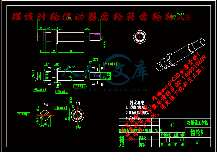
摆线针轮促动器齿轮箱齿轮轴A3.dwg
摆线针轮减速器安装支架A3.dwg
摆线针轮输入轴A3.dwg
摆线针轮齿轮箱A1.dwg
电动缸固定板.dwg
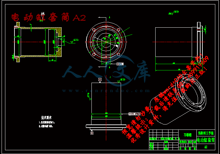
电动缸套筒A2.dwg
电动缸拉板A3.dwg
电动缸螺母A3.dwg
电机法兰A3.dwg
电机防护罩A2.dwg
齿轮轴上端盖A3.dwg
压缩包内文档预览:(预览前20页/共31页)
预览图 预览图 预览图 预览图 预览图 预览图 预览图 预览图 预览图 预览图 预览图 预览图 预览图 预览图 预览图 预览图 预览图 预览图 预览图 预览图
编号:474254    类型:共享资源    大小:2.76MB    格式:RAR    上传时间:2015-08-26 上传人:QQ14****9609 IP属地:陕西
50
积分
关 键 词:
智能 摆线 促动器 机械设计 机械设备 毕业设计 智能摆线针轮促动器的设计
资源描述:

智能摆线针轮传动器的设计

智能摆线针轮促动器的设计【优秀机械设备全套课程毕业设计含12张CAD图纸】

【带任务书+开题报告+外文翻译】【31页@正文11300字】【详情如下】【需要咨询购买全套设计请加QQ1459919609】

任务书.doc

外文翻译.pdf

外文资料译文.doc

开题报告.doc

摆线真轮促动器(A0).dwg

摆线针轮促动器齿轮箱齿轮轴A3.dwg

摆线针轮减速器安装支架A3.dwg

摆线针轮输入轴A3.dwg

摆线针轮齿轮箱A1.dwg

智能摆线真轮促动器设计.doc

电动缸固定板.dwg

电动缸套筒A2.dwg

电动缸拉板A3.dwg

电动缸螺母A3.dwg

电机法兰A3.dwg

电机防护罩A2.dwg

齿轮轴上端盖A3.dwg

任务书                                      

题目智能摆线针轮传动器的设计

主要研究

目标

(或研

究内容)研究内容:

1.技术领域:本装置涉及到一种新型电动执行器,尤其涉及大型射电望远镜主反射面主动调整系统中使用的专用电动执行器,属电动执行器技术领域。

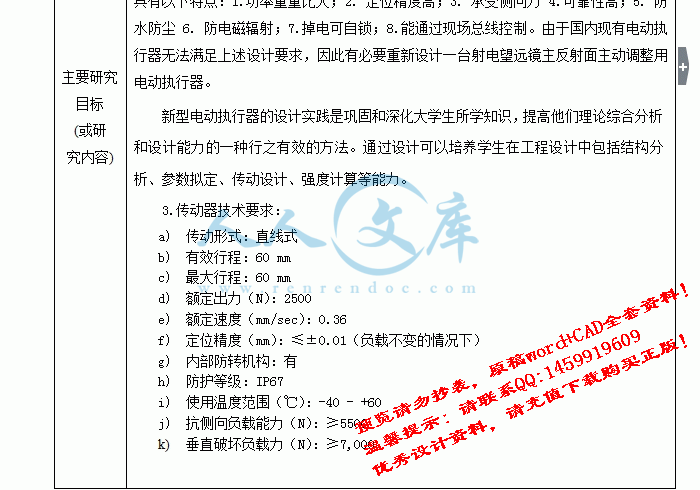
2.背景技术:大型射电望远镜由于自身重量及风载的影响,其主反射面会偏离标准抛物面形状,这会严重降低射电望远镜的效率,其高频效率更会衰减5倍以上。为了提高其高频工作效率,需要将其主反射面切割成许多小块,每一块由一台电动执行器控制,利用电动执行器的主动运动来补偿主反射面的变形量,这种技术称之为主反射面主动调整技术。该系统的核心就是主反射面主动调整用电动执行器,与其他电动执行器相比其具有以下特点:1.功率重量比大;2. 定位精度高;3. 承受侧向力 4.可靠性高;5. 防水防尘 6. 防电磁辐射;7.掉电可自锁;8.能通过现场总线控制。由于国内现有电动执行器无法满足上述设计要求,因此有必要重新设计一台射电望远镜主反射面主动调整用电动执行器。

新型电动执行器的设计实践是巩固和深化大学生所学知识,提高他们理论综合分析和设计能力的一种行之有效的方法。通过设计可以培养学生在工程设计中包括结构分析、参数拟定、传动设计、强度计算等能力。

3.传动器技术要求:

a)传动形式:直线式

b)有效行程:60 mm

c)最大行程:60 mm

d)额定出力(N):2500

e)额定速度(mm/sec):0.36

f)定位精度(mm):≤±0.01(负载不变的情况下)

g)内部防转机构:有

h)防护等级:IP67

i)使用温度范围(℃):-40 - +60

j)抗侧向负载能力(N):≥5500

k)垂直破坏负载力(N):≥7,000

课题要求、主要任务及数量(指图纸规格、张数,说明书页数、论文字数等)目标:培养学生具有独立完成较复杂的电动传动器的能力。

要求:

1. 分析题目和设计技术要求,查阅18篇以上的相关文献资料。

2. 图纸量不少于3张A0(至少1张中等难度的计算机绘图、1号图幅量的手工绘图)装配和零件图总量。验算设计参数并进行主要有零部件的强度校核;

3. 英文翻译一篇、撰写12000字的毕业设计论文、开题报告各一份。

进度计划第3周 ~ 第 5周   查阅资料,撰写开题报告

第 6周 ~ 第11周  进行结构分析,确定设计方案;对传动系统进行设计、计算,并对重要零部件进行安全与疲劳校核,最后绘制传动器零件图及装配图。

第12周 ~ 第14周  完善设计,审查图纸,翻译外文文献,写设计说明书(论文),写中文摘要并翻译。

第15周  毕业设计论文定稿,打印。

第16~17周:答辩。

主要参

考文献1)机械设计课程设计  于惠力等  科学出版社,2007?

2)  机械设计课程设计   杨光等  高等教育出版社 2010

3)  简明机械设计手册  宋宝玉等 哈尔滨工业大学出版社2008?

4)  机械设计手册.第3卷:机械零部件设计(轴系、支承与其他),?机械工业出版社,2010

5)  机械设计手册:单行本.减速器和变速器 机械设计手册编委会[编]?机械工业出版社,2007

6)  机械设计课程设计图册  向敬忠等  化学工业出版社  2009?

7)  机械设计课程设计手册  张龙  国防工业出版社,2006

8)  机械原理 (第六版)孙桓主编,北京:高等教育出版社, 2001年

智能摆线针轮促动器的设计

摘 要

促动器是调解反射面的核心部件。望远镜由于自身重量和风载的影响,反射面会有轻微的变动,促动器会进行调节。促动器的设计会影响射电望远镜的正常运行,后期维修和使用寿命。

本文主要设计的是促动器。其中包括了:智能步进电机、制动器、锥齿轮、摆线针轮减速器、滚珠丝杠等零件。促动器的精度会影响射电望远镜的精度。

考虑促动器的运动原理,了解各部件的配合情况,计算各部件的尺寸、应选用的材料并进行强度校核。基于拉杆的运动速度,计算出丝杠的转速,并根据摆线针轮的速比,计算出智能步进电机的转速。了解制动器和摆线针轮的工作原理。了解滚珠丝杠的优点,并进行滚珠丝杠的计算和强度校核。进行锥齿轮的强度校核。

关键词:智能步进电机,制动器,锥齿轮,摆线针轮减速器

THE DESIGN OF INTELLIGENT CYCLOIDAL PINWHEEL ACTUATOR

ABSTRACT

 The actuator is the core component in mediating the reflection. Due to the influence of the telescope in its weight and wind load, the reflective surface will have a slight change,then actuators will adjust. The design of the actuator will affect the normal operation of the radio telescope, the late maintenance and service life.

 The main design of this paper is the actuator, which includes: intelligent stepper motor, brake, bevel gear, cycloid pin wheel reducer, ball screw, etc. The precision of the actuator can affect the precision of the radio telescope.Considering the movement of the actuator principle, understanding the cooperation of each composition, computing the size of the parts and materials should be chosen, also checking the intensity.Based on the pull rod movement speed, to calculate the speed of a ball screw, and based on the ratio of cycloidal pinwheel, to compute intelligent stepper motor speed.Understanding the working principle of the brake and the cycloidal pinwheel.

Getting information of the advantages of ball screw, calculating the ball screw and checking the intensity.Checking intensity of the bevel gear check.

KEY WORDS:  Intelligent stepper motor,Brake,Bevel gear,Cycloidal reducer

目 录

前 言1

第1章 绪 论3

1.1 智能促动器的研究动态及选题意义3

1.1.1国内外研究3

1.1.2 促动器的传动机构原理和优点4

1.2促动器的应用6

1.3.促动器的发展趋势6

第2章 促动器的速度需求及计算7

2.1电动机的选择7

2.2联轴器的选择8

2.3齿轮轴的计算9

2.4锥齿轮的计算15

2.4.1  根据齿面接触强度计算15

2.5滚珠丝杠和电动缸的选用和计算16

2.5.1滚珠丝杠的选用17

2.5.2 滚珠丝杠的计算及强度校核18

2.5.3 电动缸的选用19

2.6轴承的选择19

第3章 箱体的设计20

3.1.电机防护罩的设计21

3.1.1电机防护罩底座的设计21

3.1.2电机防护罩和齿轮箱的连接21

3.1.3电机防护罩的内部结构21

3.2 齿轮箱的设计21

3.2.1电机防护罩和齿轮箱的连接部位22

3.2.2齿轮箱的下部位设计22

3.2.3齿轮箱端盖22

3.3  铸造工艺性23

结 论24

致 谢25

参考文献26

前 言

1608年,荷兰眼睛匠汉斯利伯为自己制作的望远镜申请了专利,并遵从当局要求,造了一个双筒望远镜。当时望远镜的消息在欧洲流传开了,伽利略得到这个消息后,他就自己制造了一个望远镜。他制作的第一架望远镜只能把物体放大3倍,第二架放大8倍,第三架放大了20倍。1609年他制作出了能放大30倍的望远镜,他用自己制作的望远镜观察晚上的夜空,第一次看见了月球的表面。同时,开普勒也开始研究望远镜,并且发明了折射望远镜。1688年,牛顿发明了反射式望远镜,解决了色差问题。

望远镜不断在更新换代,并且出现在了不同的领域。1928年美国的卡尔央基做出了世界第一架射电望远镜,并与1933年发现来自银河的电磁辐射,射电望远镜的应用发展也由此拉开序幕,世界各国竞相向太空探索。

我国也在1960年开始建立了我国第一台射电望远镜。北京50m口径和上海佘山口径65m的望远镜。近几年,我国突破了很多技术难题,在贵州平塘建造了口径达到500m的望远镜,成为了世界上最大的射电望远镜。但是,随着射电望远镜口径的增大,自身的重量和风载会对望远镜的造成影响,主反射面会偏离抛物面的形状,这也会严重降低射电望远镜的效率。其高频率更会衰减5倍以上严重影响到科学家的工作,因此我们会把切割成三角形、四边形等许多小块。然后用用一种促动器进行调节用促动器来补偿这种偏差。

我国相对于促动器的研究起步很晚,是从苏联有触电的促动器进行仿制开始的随着电子技术的高速发展,促动器的发展也很快,但是与国外一些国家的促动器知道互相比,现在国内的促动器结构仍存在控制方式落后、可靠性不高精度差等不足,因此需要设计一种智能促动器,尤其是调整大型射电望远镜主反射面主动调节促动器。属于电动执行器技术领域。与其他促动器相比该装置具有以下特点。(1)利用微机技术可以进行总场控制。(2)防磁辐射。(3)可靠性高。(4)定位精度较高。(5)功率重量比大。(6)承受侧向力(7)防尘防水(8)端的可以自锁。

参考文献

[1] 机械设计课程设计  于惠力等  科学出版社,2007?

[2] 机械设计课程设计   杨光等  高等教育出版社 2010

[3] 简明机械设计手册  宋宝玉等 哈尔滨工业大学出版社2008?

[4] 机械设计手册.第3卷:机械零部件设计(轴系、支承与其他),?机械工业出版社,2010

[5] 机械设计手册:单行本.减速器和变速器 机械设计手册编委会[编]?机械工业出版社,2007

[6] 机械设计课程设计图册  向敬忠等  化学工业出版社  2009?

[7] 机械设计课程设计手册  张龙  国防工业出版社,2006

[8] 机械原理 (第六版)孙桓主编,北京:高等教育出版社, 2001年

[9] 机械系统设计(第二版) 朱龙根主编. 北京:机械工业出版社,2001

[10]机械设计  孙志礼,冷兴聚,魏严刚等主编.  沈阳:东北大学出版社 2000

[11]材料力学  刘鸿文主编.  北京:高等教育出版社1991

[12]理论力学. 哈尔滨工业大学理论力学教研组编. 北京:高等教育出版社 1997

[13]机械原理  孙 桓,陈作模主编.  北京:高等教育出版社 2000

[14]机械设计习题与解题分析  喻子建,张磊、邵伟平、喻子建主编. 沈阳:东

北大学出版 社 2000

[15]机械设计课程设计.王昆、何小柏主编.北京:高等教育出版社,1996

[16]画法几何及机械制图. 朱冬梅、胥北澜主编.北京:高等教育出版社,2000

[17]机械设计.濮良贵,纪名刚主编.第八版.北京:高等教育出版

社,2008

[18]机械制造技术基础.曾志新,吕明主编.湖北:武汉理工大学出版社,2004


内容简介:
洛阳理工学院 毕业设计(论文)任务书 填表时间: 2015 年 3 月 5 日 (指导教师填表) 学生姓名 赵丰 专业班级 B110208 指导教师 杨奎民 课题类型 科研 题目 智能摆线针轮传动器的设计 主要研究 目标 (或研 究内容 ) 研究内容: 1.技术领域 :本装置涉及到一种新型电动执行器,尤其涉及大型射电望远镜主反射面主动调整系统中使用的专用电动执行器,属电动执行器技术领域。 2.背景技术 :大型射 电望远镜由于自身重量及风载的影响,其主反射面会偏离标准抛物面形状,这会严重降低射电望远镜的效率,其高频效率更会衰减 5 倍以上。为了提高其高频工作效率,需要将其主反射面切割成许多小块,每一块由一台电动执行器控制,利用电动执行器的主动运动来补偿主反射面的变形量,这种技术称之为主反射面主动调整技术。该系统的核心就是 主反射面主动调整用电动执行器,与其他电动执行器相比其具有以下特点: 1.功率重量比大; 2. 定位精度高; 3. 承受侧向力 4.可靠性高; 5. 防水防尘 6. 防电磁辐射; 7.掉电可自锁; 8.能通过现场总线控 制。由于国内现有电动执行器无法满足上述设计要求,因此有必要重新设计一台射电望远镜主反射面主动调整用电动执行器。 新型电动执行器的设计实践是巩固和深化大学生所学知识,提高他们理论综合分析和设计能力的一种行之有效的方法。通过设计可以培养学生在工程设计中包括结构分析、参数拟定、传动设计、强度计算等能力。 3.传动器技术要求: a) 传动形式:直线式 b) 有效行程: 60 mm c) 最大行程: 60 mm d) 额定出力( N): 2500 e) 额定速度( mm/sec): 0.36 f) 定位精度( mm): 0.01(负载不变的情况下) g) 内部防转机构: 有 h) 防护等级: IP67 i) 使用温度范围(): -40 - +60 j) 抗侧向负载能力( N): 5500 k) 垂直破坏负载力( N): 7,000 nts课题要求、主要任务及数量(指图纸规格、张数,说明书页数、论文字数等) 目标:培养学生具有独立完成较复杂的电动传动器的能力。 要求: 1. 分析题目和设计技术要求,查阅 18 篇以上的相关文献资料。 2. 图纸量不少于 3 张 A0(至少 1 张中等难度的计算机绘图、 1 号图幅量的手工绘图)装配和零件图总量。验算设计参数并进行主要有零部件的强度校核; 3. 英文翻译一篇、撰写 12000 字的毕 业设计论文、开题报告各一份。 进度计划 第 3 周 第 5 周 查阅资料,撰写开题报告 第 6 周 第 11 周 进行结构分析,确定设计方案;对传动系统进行设计、计算,并对重要零部件进行安全与疲劳校核,最后绘制传动器零件图及装配图。 第 12 周 第 14 周 完善设计,审查图纸,翻译外文文献,写设计说明书 (论文 ),写中文摘要并翻译。 第 15 周 毕业设计论文定稿,打印。 第 16 17 周:答辩。 主要参 考文献 1) 机械设计课程设计 于惠力等 科学出版社, 2007 2) 机械设计课程设计 杨光等 高等教育出版社 2010 3) 简明机械设计手册 宋宝玉等 哈尔滨工业大学出版社 2008 4) 机械设计手册第 3 卷:机械零部件设计 (轴系、支承与其他 ), 机械工业出版社,2010 5) 机械设计手册:单行本减速器和变速器 机械设计手册编委会 编 机械工业出版社, 2007 6) 机械设计课程设计图册 向敬忠等 化学工业出版社 2009 7) 机械设计课程设计手册 张龙 国防工业出版社, 2006 8) 机械原理 (第六版)孙桓主编,北京:高等教育出版社, 2001 年 指导教师签字: 系 主任签字: 年 月 日 ntsThe Eighth International Conference on Electronic Measurement and Instruments ICEMI2007 Design and Research on New Track System for Machine Tool Chen Xueli Xu Yiping He Jun (College of Electric and Automate Engineering, Nanjing Normal University,78 Bancang Street Nanjing,210042,China) Abstracts: The kernel of this system is controlled by single-chip computer type 8031 to surveillance the real-time working state of bed. It can collect three-direction cutting-force, which are created at the same time and are called Fin the computer in advancing the trend analysis of the production situation, it will be convenient for the operational and managing personnel to decide and guide production. 4-5 34XFYFZby time-sharing. Three-direction cutting-force will be converted to the variable voltage through resistance strain gage , after amplification, filtering, anti-jamming, with single-chip computer sampling and holdingAnalog-to-Digital conversion and control through multi-switch and then putting the results in the memorizer. The system is expanded with the function of print display keyboard and so on and enhanced the function of man-machine dialogue . This paper introduces a design and research on new track system for machine tool. The single-chip microcomputer used for real-time tracking, the machine tool is characterized by the simple structure, low prices and reliability and stability. With a good man-machine interface, normative data can be produced conveniently. The design and research on new track system for machine tool refer to sensors, electronic circuits, computers and other fields, which is the hot field currently . Keyboards: data acquisition real-time monitor single-chip computer 11 Introduction 2 Summarization During the industrial production, there are a large number of parameters ,such as pressure temperature speed and so on, needing for roving detection data processing analysis record and alarm when the parameters are at a high pitch . The cutting force of the machine tool is one of the main parameters in industrial control targets. As far as this type of control objects is concerned, because of their grate changing rate, artificial observations had been used to regulate the relating parameters in the past with the low control accuracy and incapable of recording the data. This paper is adopted with the single-chip computer to monitor the working condition of the bed automatically to improve the control accuracy and the automation. Through the real-time analysis of a lot of parameters accumulated This system that is named the real-time monitoring system of the three-direction cutting-force is composed of sensors amplifiers multi-switchAnalog-to-Digital converter and single-chip microcomputer 8031 .The diagram of the system is in figure 1. 2Because the working environment of the sensor is usually complex and poor during the system, the greater interference signal that is noise is produced in the two output lines of the sensor. Although the operational amplifier can suppress the common-mode signal which is input to the differential end directly, the suppression ability is rather worse. To ensure the measurement results, we choose the high-performance differential amplifier which is made up of n closed-loop operational amplifiers in the system, which has the good performance and simple hardware 1-4244-1135-1/07/$25.00 2007 IEEE.ntsThe Eighth International Conference on Electronic Measurement and Instruments ICEMI2007 connection.4-544The three-direction sensors will make each power amplify and filter and then send into the converter. The power will be converted to the digital value. The device is required the largest Fz of the measurement is 450Kg, so the resolution must be less than 1/450, if we choose 8-bit Analog-to-Digital converter, the resolution of which is 1/256 that can not meet the requirement, so the 12-bit Analog-to-Digital converter is adopted, the resolution of which is 1/4096 that can meet the technical requirement. This system is used AD574 conversion chip, the resolution of which is 12. In addition, the system has also been expanded with three pieces of chip that are used as the interface of the printer, which is RAM, ROM and 8155. The special interface chip 8279 provides the programmable interface of the keyboard and digital display . In this paper, the choice of sensors and the analysis of the measurement principle are introduced in detail. 8031RORAI/O printerI/OdisplaykeyboardFx sensorsFy sensorsFz sensorsAmplifier FilterAmplifier FilterAmplifier Filtermulti-switchA/DS/HExternal controllerFig.1 The diagram of the system3 Choice of sensors and the analysis of the measurement principleThe resistance value varies correspondingly when the wire brings mechanical deformation under the action of outside force and this physical phenomenon is called the strain effect of the resistance wire. Resistance strain gage is one kind of the common sensors which is used to measure objects stress and distortion which produces deformation, which is a sensing component capable of converting the mechanical sample changes into the resistance changes, that is, using resistance strain gages as transition element which changes force into electricity.The principle of the strain effect of the resistance wire is as follows: suppose there is a metal resistance wire, the situation of the fore-and-aft deformation is shown in figure 2. 3When the resistance wire does not accept the outside ldlFF2r+2drFig 2. the diagram of resistance line faced ntsThe Eighth International Conference on Electronic Measurement and Instruments ICEMI2007 force that is F equals zero, the resistance value is: xdxRdRKHUUPH/)21(/0 6K0is the strain sensitive coefficient of the wire which : SLR U 1UIn the formula, stands resistivity while L stands the length of the resistance wire and S stands the resistance area of section mmdenotes that the unit axial strain of the wire brings the corresponding change of the resistance value. It can be known through the sixth formula that K24-545 .0is composed of two items. The first is the sum of one and doubleP ,which shows the change of the resistance because f the change of the geometrical size. The other one is Suppose the resistance wire accepts the outside force F and the acting force along the axial of the resistance wire is uniform stress, when the length changes, the area of the section changes and the radius changes and the resistivity changesodsdr UdxdHUU /metals and its value is quite small, so it can be neglected. Therefore: , which shows the change of the resistivity by the unit axial strain. It is also a constant to most .Because 2ds drs r , the change of the resistance is: dR2(l ldldsdl ds d Rsls)ddRsU UUUP210 K 7an be seen that K0is a constan anU 2We make both sides of the second fordivide R and the result is: It is c t which c be mula 2dR dl dr dRl rUU 3We make / =obtained through the experiment and it is usually 1.6 to 2. 0RK xRH 8change of the resista e l adde suffers in gages dl l xH that is elongation which is the axial strai able,tes he hanthe axial relative n micro-vari We measure the nce after th o that is the relative change of the wiry resistance should be in the direct proportion with the axial strain. If the unilateral radial force Fy is applied in the ring, which indica t c ge of the unit length because of the load. We make dr / r = yH that is the radial relative the strain of the ring is different everywhere and the strain is zero where the angle with the acting force is 39.6 degree which is shown is figure 3( a). There is the maximal strain in the horizontal center line. If the resistance strain gauge is affixed here, there will be the best sensitivity. R1 and R3 suffer tensile stress while R2 and R4 suffer compressive stress. If one side of the ring is fixed, the other sielongation w h is th dial strain micro-variable. The relation of them is: 0 y=-0 x 4 is the Poisson ratio ofhic e rathe resistance wire material, which ngation and the is ratio of the axial relative eloradial relative reduction. usually is 0.3 to 0.5. The change of the measuring resistance is as follows: the tangential force that is Fx which is shown in figure 3 b , in this way, there is the maximal strain where the angle with the vertical center is 39.6 degree. If the resistance strain gauge is affixed here, there will be the best sensitivity. R5 and R7 suffer tensile stress while R6 and R8 suffer compressive stress. It is completely similar that the resistance stradRR UUHPUUPHHUUHHdxdxxdyx )21(22 5 Both sides of the equation divide 0 x anwill get: d we ntsThe Eighth International Conference on Electronic Measurement and Instruments ICEMI2007 FyR2R4R1 R3(a)Fx39.6eR8R7R6R5(b)R4 R3 R12 R11R9 R10 R1 R2R5R6R8R7( c) UyR1R4R3R2U0 (d)Fig 3. The diagram of measuring on three-direction cutting-force R9 to R12 which are used to measure the main cutting changes because of the cutting, we can n Because the working environment of the sensor is output lines . In testing device, we can use ost widely, which is the with the time, we still need to connect a force called Fz should be affixed to the horizontal center line. In this way, when the resistance produces the corresponding4-546make use of the bridge to transform the resistance variation into the voltage variation. The bridge measurement is easy, furthermore, the accuracy and the sensitivity are upper. When the ring accepts Fy, Fz and Fx simultaneously, we make the resistance strain gages R1 to R4, R5 to R8, R9 to R12 buildup bridge separately which will be able to test Fy, Fx and Fz mutually non-interferential. The figure 3(d) shows the bridge circuit of one direction that is y direction. Because the ring is not easy to clamp and fix, in fact, we use the octagonal ring to instead, which is showin figure 3(c). The octagonal ring is also the common elastic component as the multidirectional ergometer. When the cutting tool is cut in the octagonal ring, according to the corresponding information produced by the direction and the size of cutting force, it can be cut accurately basing on the information. usually complex and poor, the greater interference signal that is noise is produced in the twoof the sensor. To ensure the measurement results, we can choose the instrumental amplifier which is also known as the data amplifier. The device is chosen AD521 which has the good performance and simple hardware connection. Filter is a frequency-selective device, which makes the special frequency of the signal pass while reduces other ingredients greatlythe filtrating function of the filter to filtrate and eliminate interferential noise. The system is used first order Resistance-Capacitance low-pass filter to restrain interference. In a microcomputer detection system, multi-channel analog switch with integrating in one chip and multi-model is used mstandard and dual inline type structure, which is also small in size and easy to install. When the input analog signal varies rapidly along ntsThe Eighth International Conference on Electronic Measurement and Instruments ICEMI2007 4-547sample-and-hold device in the input channel. There are two kind of working way that is the sampling way chine tool is widely used in the industrial production, which is le structure, low prices and reliability and stability. With a good man-machine 07111XLH0037control. 2004.4,P325-328 , Design and Research on New Intelligent ontrol System for Stove,JOURNAL OF 4 e Monitor Cre land the holding way, which is selected by the end of the control. The system is used LS398. 4 Conclusion The design on new track system for macharacterized by the simpinterface and the better real-time ability, it will be convenient to produce the normative data4. The system refers to sensors, electronic circuits, computers and other fields, which is the hot field currently. Nowadays, some scientific research institutes are doing this research and have made some achievement, but there are still some problems which need to be explored.AcknowledgmentsThe project is supported by Fund of nanjing normal university 20References 1 Qi yuefeng, design on distributed test system for big bridge health computer survey and 2 Chen xueliTemperature CCHINA UNIVERSITY OF MINING AND TECHNOLOGY .2001.12,Vol.11,No.2,P217-220 3 zhang weixi,nanjing university publishing house.2001.1.&KHQXHOL Design and Research on Real-TimSystem for Plants Environmental State in The GreenhouseISTAI 2006 Proceedings 2006.9 Vo l . 2 1158-1161. thor Biographies Auhen xueli: (1960-) female ,a professor engaged in the search on computer engineering in Nanjing NormaUniversity Jiangsu Province. nts外文资料译文 第八届电子测量与仪器国际会议 机床新跟踪系统的设计和研究 陈雪 丽 徐一平 何军 电气与自动化工程学院,南京师范大学,板仓街 78 南京, 210042,中国 摘要 该系统由单片机 8031 型控制,来监控机床的实时工作状态。它可以收集三向切削力,并且这是建立在同一时间的,在分时操作中被称为 Fx 、 Fy、 Fz。在放大、滤波、抗干扰、单片机采样和保持,通过多路开关模拟 数字转换和控制,然后把结果存置存储器之后,三向切削力将通过电阻应变计转换为可变电压。该系统被扩展之后兼具打印、 显示和键盘等诸多功能,同时也增强了人机对话的功能。 关键词 :数据采集 实时 监控 单片机 1.简介 在工业生产 ,有大量的参数 ,如压力、温度、速度等 ,当对参数要求很高时,它们需要一系列的巡回检测、数据处理、分析、记录和报警。在工业控制目标中机床的切削力是一个主要参数。对这种类型的控制对象而言 ,由于他们的炉篦改变率 , 在过去控制精度低和不能记录数据的情况下,人工观测已经用来调节相关参数。本文采用单片机自动监控机床的工作状态来提高控制精度和自动化的水平。通过对积累在电脑里的大量数据的实时分析来达到改进生产 情况的趋势分析,这样方便操作人员和管理人员决定和指导生产。本文介绍一种对机床导轨系统新的设计和研究。单片机微型计算机用于实时跟踪,机床具有结构简单、价格低、可靠性和稳定性的优点。在一个良好的人机界面,规范的数据就可以方便的产生。设计与研究机床新的跟踪系统是指传感器、电子电路、计算机等领域,这依然是目前的热点领域。 nts2.概要 该系统,即三向切削力实时监控系统,由传感器、放大器、多开关、模拟 -数字转换器和单片微型机 8031(注释)构成。图 1 为该系统图解 。 图 1.系统图解 由于在系统里传感器的工 作环境通常是复杂且不佳的,更强烈的干扰信号即噪音是在传感器的两根输出线中产生的。虽然运算放大器可以抑制直接输入到差速器的共模信号,但是这种抑制能力很差。为保证测量结果,我们在系统中选择由闭环运算放大器组成的高性能差分放大器,它性能好硬件连接件简单。 三方向传感器将使每个功率放大和滤波后送入转换器。电力将被转换为数字值。该装置所需的最大测量 FZ 是 450 公斤,所以分辨率必须小于 1 / 450,如果我们选择了 8 位模拟数字转换器,其分辨率为 1 256,不能满足要求,所以我们采用 12 位模数转换器,其分辨率为 1 / 4096,即可满足技术要求。本系统采用AD574 转换芯片,其分辨率为 12。 此外,该系统也也已扩大为使用三块芯片即 RAM,ROM,和 8155,作为打印机的接口。这个专用接口芯片 8279 提供键盘和数字展示的可编程接口。本文将详细介绍传感器的选择和测量原理的分析。 3.传感器的选择和测量原理的分析 当在外力作用下线使机械变形时电阻值也会发生相应变化,这一物理现象称为电阻丝的应变效应。电阻应变计是一种常见的传感,用于测量物体的应力和畸变产生的变形,是一个遥感组件能够把机械样本变化转换成阻力变化,即把电阻应变计作 为过渡元素,将力转化为电能。电阻丝应变效应的原理如下:假设有一nts个金属电阻丝,它的纵向变形情况显示为图 2。 图 2 表面阻力示意图 当电阻丝不受外力 F, F 为零,电阻值为 SLR (1) 在公式中,代表电阻率, L 代表电阻丝的长 度 , S 代表截面阻力区域( mm)。假设电阻丝受外力 F 而且电阻丝的轴向作用力是均匀应力,当长度变化时,这部分 的截面阻力区域即变为 ds ,半径为 dr,电阻率为 d 。因为rdrs 2ds , 所以电阻率 dR变为 dsdsldlRdsldss ldlsdR 2( 2) 我们把第二个公式的两边同除以 R,得到 drdrldlRR 2d( 3) 我们使 xll /d , 这是轴向相对伸长率,即轴向应变的微变量,这表明由于负载单位长度发生的变化。 我们使 yrr /d ,这是径向相对伸长率,即径向应变微变量
温馨提示:
1: 本站所有资源如无特殊说明,都需要本地电脑安装OFFICE2007和PDF阅读器。图纸软件为CAD,CAXA,PROE,UG,SolidWorks等.压缩文件请下载最新的WinRAR软件解压。
2: 本站的文档不包含任何第三方提供的附件图纸等,如果需要附件,请联系上传者。文件的所有权益归上传用户所有。
3.本站RAR压缩包中若带图纸,网页内容里面会有图纸预览,若没有图纸预览就没有图纸。
4. 未经权益所有人同意不得将文件中的内容挪作商业或盈利用途。
5. 人人文库网仅提供信息存储空间,仅对用户上传内容的表现方式做保护处理,对用户上传分享的文档内容本身不做任何修改或编辑,并不能对任何下载内容负责。
6. 下载文件中如有侵权或不适当内容,请与我们联系,我们立即纠正。
7. 本站不保证下载资源的准确性、安全性和完整性, 同时也不承担用户因使用这些下载资源对自己和他人造成任何形式的伤害或损失。
提示  人人文库网所有资源均是用户自行上传分享,仅供网友学习交流,未经上传用户书面授权,请勿作他用。
关于本文
本文标题:智能摆线针轮促动器的设计【优秀机械设备全套课程毕业设计含12张CAD图纸】
链接地址:https://www.renrendoc.com/p-474254.html

官方联系方式

2:不支持迅雷下载,请使用浏览器下载   
3:不支持QQ浏览器下载,请用其他浏览器   
4:下载后的文档和图纸-无水印   
5:文档经过压缩,下载后原文更清晰   
关于我们 - 网站声明 - 网站地图 - 资源地图 - 友情链接 - 网站客服 - 联系我们

网站客服QQ:2881952447     

copyright@ 2020-2025  renrendoc.com 人人文库版权所有   联系电话:400-852-1180

备案号:蜀ICP备2022000484号-2       经营许可证: 川B2-20220663       公网安备川公网安备: 51019002004831号

本站为文档C2C交易模式,即用户上传的文档直接被用户下载,本站只是中间服务平台,本站所有文档下载所得的收益归上传人(含作者)所有。人人文库网仅提供信息存储空间,仅对用户上传内容的表现方式做保护处理,对上载内容本身不做任何修改或编辑。若文档所含内容侵犯了您的版权或隐私,请立即通知人人文库网,我们立即给予删除!