翻译原文.doc

352履带拖拉机-单级最终传动装置设计【优秀含4张CAD图纸+汽车车辆全套毕业设计】

收藏

压缩包内文档预览:
预览图 预览图 预览图 预览图 预览图
编号:474496    类型:共享资源    大小:985.13KB    格式:ZIP    上传时间:2015-08-27 上传人:小*** IP属地:福建
50
积分
关 键 词:
履带 拖拉机 最终传动 装置 设计 优秀 优良 cad 图纸 汽车 车辆 全套 毕业设计
资源描述:

!【详情如下】【汽车车辆工程类课题】CAD图纸+word设计说明书.doc[15000字,44页]【需要咨询购买全套设计请加QQ97666224】.bat

352履带拖拉机-单级最终传动装置设计(有cad原图+中英文翻译).doc

A.1开题报告.doc

任务书.doc

摘要、目录.doc

翻译原文.doc

设计说明书.doc[15000字,44页]

转向系统--中英文翻译.doc

主动齿轮.dwg

从动鼓接盘.dwg

从动齿轮.dwg

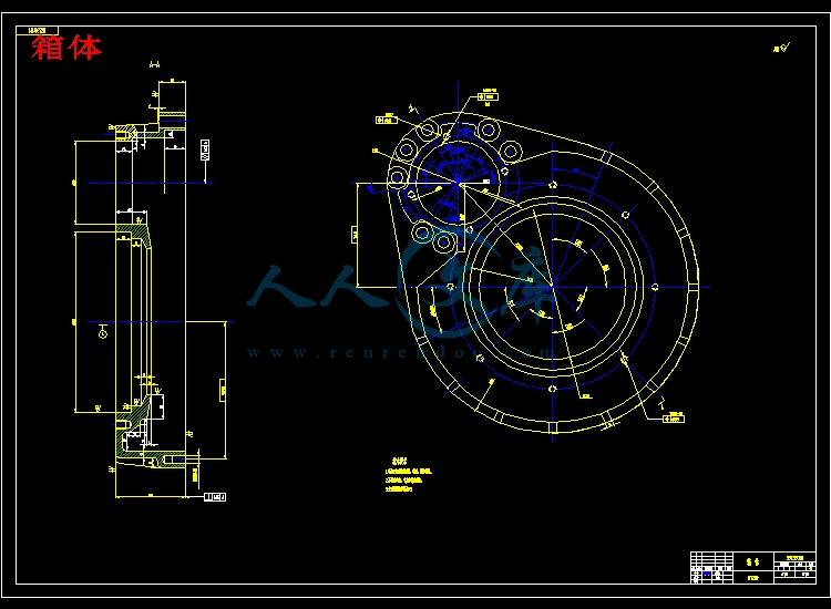
箱体.dwg


摘要


履带式拖拉机能够正常行驶,拖拉机驱动轮需要足够的驱动力。这就需要一套能够增加传动系的传动比的专署机构。它将进一步降低驱动轮转速,从而提高驱动轮的转矩,这就是所谓的最终传动。同时履带式拖拉机的最终传动还用来提高后桥的离地间隙。所以最终传动要有适当的传动比;保证后桥处有足够的离地间隙;齿轮要具有较高的支承刚度;靠近驱动轮布置的最终传动尤其要有可靠的密封。

外置式外啮合圆柱齿轮最终传动,使最终传动成为一个独立部件,便于拆装和维修。这种结构的主、从动齿轮在壳体内的支持可以布置成简支梁式,对提高支撑刚度有利。主动轮的啮合条件降低了轮齿上的载荷,提高了承载能力,但结构复杂。

最终传动的传动比较大,齿轮和轴受载严重,径向尺寸受到轮辋尺寸和离地间隙的限制而不能太大。为了在结构紧凑的情况下,保证齿轮有足够的强度,外啮合圆锥齿轮的最终传动常常采用较大的齿宽和较少的齿数。为了保持齿轮的良好啮合,必须保证两齿轮轴中心线的平行度。


关键词:主动齿轮,最终传动,直齿,保护板


TGHE FINAL DRIVES DESIN

ABSTRACT


Track type tractor can be normal to drive, the tractor drives a demand to drive the dint enough . This need a set of canning increase to spread to move is of spread the exclusive organization that move compare. It will further lower to drive the rotation soon, from but the exaltation drives a the round turns to be apart from, this is so-called of end spread to move .At the same time track type tractor of end spread to move to still use  to leave a cleft after increasing to the bridge.

Outside install outside the place type matches the cylinder wheel gear the end spreading moves, making end spreading moved to become an independent parts, easy to dismantle to pack with maintain. This kind of structural lord, from move the wheel gear to can arrange in the hull support in a beam type, prop up to the exaltation just the degree is beneficial .Install of the active round matches the term lowers a ascends of is increases by dint, loading ability, but the construction sophisticates.

It is end to spread to spread to move dynamically bigger, the wheel gear suffers to carry with stalk seriously, the path is left by a  size with toward size the restrict of a ground of clefts but can't be too big. For the sake of under the situation that construction tightly packed, guarantee to wheel gear contain enough strength, the outside match the cone wheel gear end to spread to move to usually adopt the bigger breadth with the number of the less.


KEY WORD:Drive gear wheel , The final drive, Spur gear,Guard


目  录

第一章  前言....................................... ....1

第二章  传动系统概述....................................2

第三章  最终传动概述....................................3

§3.1 最终传动装置的功用和要求.................... ..3

§3.2  最终传动的分类、结构分析及评价..................3

§3.2.1 外啮合圆柱齿轮最终传动.................... .3

§3.2.2 内啮合圆柱齿轮最终传动......................4

§3.2.3 行星齿轮最终传动............................4

§3.3  最终传动的传动方案及结构简图...................4

第四章  总体设计.....................................6

§4.1机械式传动系统总传动比及各部件传动比的确定......6

§4.1.1 传动系的总传动比............................6

§4.1.2 总传动比在各部件间的分配....................7

第五章  最终传动装置设计................................8

§5.1 最终传动装置主要参数的选择......................8

§5.2  最终传动装置强度校核..........................9

§5.2.1 齿轮强度校核............................... 9

§5.2.2 轴承寿命校核............................. .18

§5.2.3 轴强度校核.................................20

§5.2.4 螺栓强度校核...............................22

第六章  结论................................. .........26

参考文献...............................................27

致谢..................................... .............28


内容简介:
THE STEERING SYSTEM The steering system enables the driver to guide the automobile or wheeled tractor down the road and turn right or left, as desired, by turning wheels, There are two types of steering systems. These are manual and power. 1. Power Steering There are a couple of key components in power steering in addition to the rack-and-pinion or recalculating-ball mechanism. 2. Pump The hydraulic power for the steering is provided by a rotary-vane pump (see diagram below). This pump is driven by the cars engine via a belt and pulley. It contains a set of retractable vanes that spin inside an oval chamber. As the vanes spin, they pull hydraulic fluid from the return line at low pressure and force it into the outlet at high pressure. The amount of flow provided by the pump depends on the cars engine speed. The pump must be designed to provide adequate ntsflow when the engine is idling. As a result, the pump moves much more fluid than necessary when the engine is running at faster speeds. The pump contains a pressure-relief valve to make sure that the pressure does not get too high, especially at high engine speeds when so much fluid is being pumped. 3. Rotary Valve A power-steering system should assist the driver only when he is exerting force on the steering wheel (such as when starting a turn). When the driver is not exerting force (such as when driving in a straight line), the system shouldnt provide any assist. The device that senses the force on the steering wheel is called the rotary valve. The key to the rotary valve is a torsion bar. The torsion bar is a thin rod of metal that twists when torque is applied to it. The top of the bar is connected to the steering wheel, and the bottom of the bar is connected to the pinion or worm gear (which turns the wheels), so the amount of torque in the torsion bar is equal to the amount of torque the driver is using to turn the wheels. The more torque the driver uses to turn the wheels, the more the bar twists. The input from the steering shaft forms the inner part of a spool-valve assembly. It also connects to the top end of the torsion bar. The bottom of the torsion bar connects to the outer part of the spool valve. The torsion bar also turns the output of the steering gear, connecting to either the pinion gear or the worm gear depending on which type of steering the car has. As the bar twists, it rotates the inside of the spool valve relative to the outside. Since the inner part of the spool valve is also connected to the steering shaft (and therefore to the steering wheel), the amount of rotation between the inner and outer parts of the spool valve depends on how much torque the driver applies to the steering wheel. Animation showing what happens inside the rotary valve when you first start to turn the steering wheel When the steering wheel is not being turned, both hydraulic lines provide the same amount of pressure to the steering gear. But if the spool valve is turned one way or the other, ports open up to provide high-pressure fluid to the appropriate line. ntsIt turns out that this type of power-steering system is pretty inefficient. Lets take a look at some advances well see in coming years that will help improve efficiency. 4. The Future of Power Steering Since the power-steering pump on most cars today runs constantly, pumping fluid all the time, it wastes horsepower. This wasted power translates into wasted fuel. You can expect to see several innovations that will improve fuel economy. One of the coolest ideas on the drawing board is the steer-by-wire or drive-by-wire system. These systems would completely eliminate the mechanical connection between the steering wheel and the steering, replacing it with a purely electronic control system. Essentially, the steering wheel would work like the one you can buy for your home computer to play games. It would contain sensors that tell the car what the driver is doing with the wheel, and have some motors in it to provide the driver with feedback on what the car is doing. The output of these sensors would be used to control a motorized steering system. This would free up space in the engine compartment by eliminating the steering shaft. It would also reduce vibration inside the car. General Motors has introduced a concept car, the Hy-wire, that features this type of driving system. One of the most exciting things about the drive-by-wire system in the GM Hy-wire is that you can fine-tune vehicle handling without changing anything in the cars mechanical components - all it takes to adjust the steering is some new computer software. In future drive-by-wire vehicles, you will most likely be able to configure the controls exactly to your liking by pressing a few buttons, just like you might adjust the seat position in a car today. It would also be possible in this sort of system to store distinct control preferences for each driver in the family. In the past fifty years, car steering systems havent changed much. But in the next decade, well see advances in car steering that will result in more efficient cars and a more comfortable ride. 5. The Honda Insight uses a variable-assist rack and pinion electric power steering (EPS) system rather than a typical hydraulic power steering system. A typical hydraulic power steering system is continually placing a s mall load on the engine, even when no steering assist is required. Because the EPS system only needs to draw electric power when steering assist is required, no extra energy is needed when cruising, improving fuel efficiency. Electric power steering (EPS) is mechanically simpler than a hydraulic system, meaning that it should be more reliable. The EPS system is also designed to provide good road feel and responsiveness. The Insights EPS system shares parts with the Honda S2000 steering system. The systems compactness and simplicity offer more design freedom in terms of placement within the chassis. The steering rack, electric drive and forged-aluminum tie rods are all mounted high on the bulkhead, and steer the wheels via steering links on each front suspension strut. This location was chosen in order to achieve a more compact engine compartment, while improving safety. The system is also smoother operating, more responsive to driver input, and has minimal steering kickback. The overall steering ratio is 16.4 to 1, and 3.32 turns lock-to-lock. EPS Operation The operating principle of the EPS is basically the same as hydraulic power steering except for the following: nts A torque sensor is used in place of the valve body unit An electric assist motor is used in place of the hydraulic power cylinder An EPS control unit is added Mechanical Construction The rack is unusual in that it is mounted high on the rear engine bulkhead, and that the tie rods engage the rack in the center. The high mount location is used for crash safety, as it keeps these components out of the Insights crumple zone. The tie rods are aluminum, and they connect to an ackerman arm that is mounted to the struts just below the spring seat. The EPS control unit is mounted inside the car on the right side bulkhead, underneath the dash. It receives input from the vehicle speed sensor and torque sensor mounted on the steering pinion shaft. The torque sensor is identical in construction to the unit on the S2000. The pinion shaft engages the pinion gear via a torsion bar, which twists slightly when there is a high amount of steering resistance. The amount of twist is in proportion to both the amount of resistance to wheel turning, and to the steering force applied. A pin on the torsion bar engages a diagonal slot in the sensor core, which moves up or down depending on the amount of torsion bar twist, and the direction of rotation. Two coils surrounding the core detect both the amount, and the direction of movement. Using this information, the EPS control unit determines both the amount of steering assist required, and the direction. It then supplies current to the motor for steering assist. The amount of assist is also modified in proportion to vehicle speed to maintain good steering feel. Torque Sensor The torque sensor is a device to detect steering turning direction and read resistance. The sensing section of the torque sensor consists of two coils and a core (slider). The steering input shaft and pinion gear are connected via a torsion bar. The slider is engaged with the pinion gear in a way that it turns together with the pinion gear but can move vertically. A guide pin is provided on the input shaft and the pin is in a slant groove on the slider. When road resistance is low, the steering input shaft, pinion gear and slider turn together without the sliders vertical movement. When road resistance is high, the torsion bar twists and causes a difference of steering angle between the input shaft and pinion gear. In other words, the turning angle of the guide pin and slider differ, and the guide pin forces the slider to move upward or downward. Steering System The steering system must deliver precise directional control. And it must do so requiring little driver effort at the steering wheel. Truck steering systems are either manual or power assisted, with power assist units using either hydraulic or air assist setups to make steering effort easier. In addition to its vital role in vehicle control, the steering system is closely related to front suspension , axle, and wheel/tire components. Improper steering adjustment can lead to alignment and tire wear problems. Suspension, axle, and wheel problem can affect steering and h
温馨提示:
1: 本站所有资源如无特殊说明,都需要本地电脑安装OFFICE2007和PDF阅读器。图纸软件为CAD,CAXA,PROE,UG,SolidWorks等.压缩文件请下载最新的WinRAR软件解压。
2: 本站的文档不包含任何第三方提供的附件图纸等,如果需要附件,请联系上传者。文件的所有权益归上传用户所有。
3.本站RAR压缩包中若带图纸,网页内容里面会有图纸预览,若没有图纸预览就没有图纸。
4. 未经权益所有人同意不得将文件中的内容挪作商业或盈利用途。
5. 人人文库网仅提供信息存储空间,仅对用户上传内容的表现方式做保护处理,对用户上传分享的文档内容本身不做任何修改或编辑,并不能对任何下载内容负责。
6. 下载文件中如有侵权或不适当内容,请与我们联系,我们立即纠正。
7. 本站不保证下载资源的准确性、安全性和完整性, 同时也不承担用户因使用这些下载资源对自己和他人造成任何形式的伤害或损失。
提示  人人文库网所有资源均是用户自行上传分享,仅供网友学习交流,未经上传用户书面授权,请勿作他用。
关于本文
本文标题:352履带拖拉机-单级最终传动装置设计【优秀含4张CAD图纸+汽车车辆全套毕业设计】
链接地址:https://www.renrendoc.com/p-474496.html

官方联系方式

2:不支持迅雷下载,请使用浏览器下载   
3:不支持QQ浏览器下载,请用其他浏览器   
4:下载后的文档和图纸-无水印   
5:文档经过压缩,下载后原文更清晰   
关于我们 - 网站声明 - 网站地图 - 资源地图 - 友情链接 - 网站客服 - 联系我们

网站客服QQ:2881952447     

copyright@ 2020-2025  renrendoc.com 人人文库版权所有   联系电话:400-852-1180

备案号:蜀ICP备2022000484号-2       经营许可证: 川B2-20220663       公网安备川公网安备: 51019002004831号

本站为文档C2C交易模式,即用户上传的文档直接被用户下载,本站只是中间服务平台,本站所有文档下载所得的收益归上传人(含作者)所有。人人文库网仅提供信息存储空间,仅对用户上传内容的表现方式做保护处理,对上载内容本身不做任何修改或编辑。若文档所含内容侵犯了您的版权或隐私,请立即通知人人文库网,我们立即给予删除!