液压机械变速箱闭式试验台设计.doc

液压机械变速箱闭式试验台的设计【优秀试验台全套课程毕业设计含2张CAD图纸】

收藏

压缩包内文档预览:(预览前20页/共49页)
预览图 预览图 预览图 预览图 预览图 预览图 预览图 预览图 预览图 预览图 预览图 预览图 预览图 预览图 预览图 预览图 预览图 预览图 预览图 预览图
编号:475077    类型:共享资源    大小:1.78MB    格式:RAR    上传时间:2015-08-29 上传人:QQ14****9609 IP属地:陕西
35
积分
关 键 词:
液压 机械变速箱 试验台 机械设计 课程毕业设计 液压机械变速箱闭式试验台的设计
资源描述:

液压机械变速箱闭式试验台设计

液压机械变速箱闭式试验台的设计【优秀试验台全套课程毕业设计含2张CAD图纸】

【带外文翻译】【37页@正文17200字】【详情如下】【需要咨询购买全套设计请加QQ1459919609】

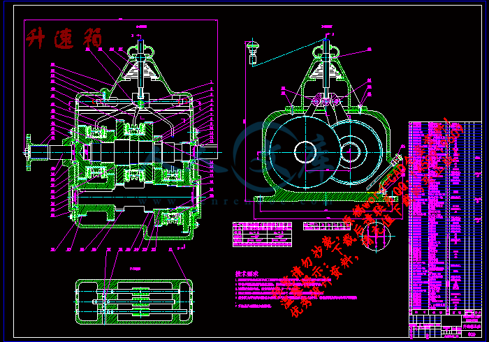
升速箱.dwg

摘要.doc

汽车发动机如何工作--中英文翻译.doc

液压机械变速箱闭式试验台设计.doc

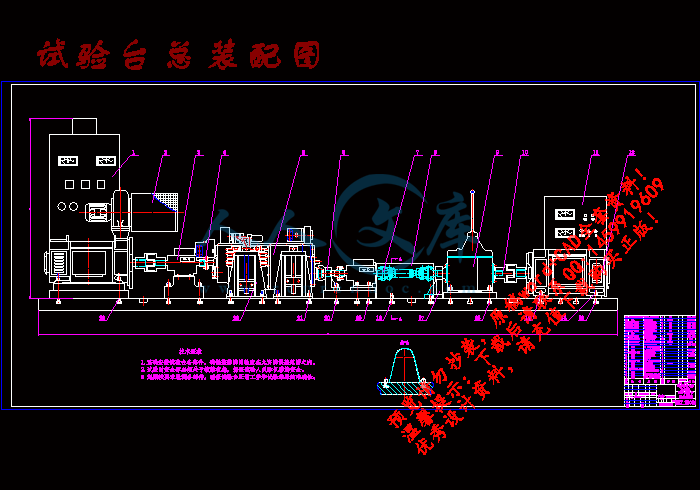
试验台总装配图.dwg

液压机械变速箱闭式试验台设计

摘 要

随着汽车工业的迅猛发展,变速箱作为汽车的重要传动部件,其操作性、传动性与安全性日显重要,为了缩短汽车变速箱的开发周期,降低研发成本,本论文以河南科技大学研发的1302R_HMT系统为基础,对液压机械变速箱的检测项目及检测方法进行了研究,设计和研发了“汽车变速箱性能检测系统”。本论文由以下几个部分组成:

1.系统的组成

试验台由直流电动机提供动力,利用快速安装机构定位、安装被测试的HMT;选NJ型转矩传感器作为力矩检测装置,选用直流发电机为加载装置,然后根据HMT的动力输出与加载装置的工作需求设计升速箱。

2.信号采集与处理

利用本校车动学院开发的PCM3132数据采集系统采集HMT的输入、输出转矩、转矩、油压、流量、温度等参数,为试验提供参考数据。通过A/D转换,由计算机屏幕显示。

根据以上分析,综合现有控制方案的特点的基础上给出了一种新型的变速箱试验台控制方案——直流电封闭机械传动试验台,并深入分析了其组成和工作原理,给出了硬件结构图和工作原理图,在此基础上根据模拟加载技术的要求提出了实现模拟加载功能的技术方案,对其中的一些关键环节进行了技术分析。该试验台实用性强,具有很高的推广价值。

关键词:功率封闭,电加载,变速箱,能量反馈

THE DESIGN OF THE DYNAMIC SIMULATION

BENCH FOR TRACTOR HYDRAULIC

MECHANICAL TRANSMISSION

ABSTRACT

With the rapid development of motorcar industries, the performance of gearbox is becoming more and more important. In order to shorten the development period of automatic transmissions of motorcar and reduce the research cost, this paper regards the HMT dynamic system of 1302R of Henan University of Science and Technology as the research background, and carried on a research about the test item and the method, then developed a test system for the performance of HMT. This article consists of several components below:

First, we introduce the system’s structure in general: the tester’s energy is provided by the direct current motive, making use of the quickly install equipment of fixed the position of HMT; choosing the NJ type’s torque equipment to test the torque, choosing the direct current generator as an add device, then design a gearbox according to the output power of the HMT.

Second, using the PCM3132 detecting the system’s oil pressure, controlling oil pressure, cooling flow or discharge etc, all these above parameters will contribute to diagnose the HMT. These signals can be output to the screen and displayed through an A/D change.

This paper introduces the components and working principle of the DC-power closed mechanical drive tester, on the basis of which the analog loading scheme of the DC power closed tester is presented an implemented, according to the requirement of analog loading technology. Some of the key links are described carefully. This test bench is useful and valuable to popularize.

KEY WORDS: Power closed, Electronically loading, Transmission, Energy return

目 录

摘要 ┅┅┅┅┅┅┅┅┅┅┅┅┅┅┅┅┅┅┅┅Ⅰ—Ⅰ

Abstract ┅┅┅┅┅┅┅┅┅┅┅┅┅┅┅┅┅┅Ⅱ—Ⅱ

前言 ┅┅┅┅┅┅┅┅┅┅┅┅┅┅┅┅┅┅┅┅┅┅3

第一章概  述┅┅┅┅┅┅┅┅┅┅┅┅┅┅┅┅┅┅4

§1.1 设计(或研究)的依据或意义┅┅┅┅┅┅┅┅┅┅4

§1.2 国内外同类设计(或同类研究)的概况 ┅┅┅┅4

§1.3 课题设计(或研究)的内容  ┅┅┅┅┅┅┅┅┅┅5

第二章液压机械无级变速箱的结构原理及功用  ┅┅┅6

§2.1 液压机械变速箱的传动原理及其功用………………6

§2.2 液压机械变速箱的结构原理图…………………………7

第三章变速箱试验台设计方案研究  ┅┅┅┅┅┅┅┅8

§3.1  试验台方案的确定 ………………………………………8

§3.2  试验台的组成及其基本功能  ………………………10

§3.3  试验台工作原理与HMT性能参数的测定 ………11

§3.4  动力输入(电动机) 的计算与选择…………………12

§3.5  联轴器的计算与设计  …………………………………15

§3.6  变速箱快速安装机构设计 ……………………………18

§3.7  传动机构的计算与设计…………………………………19

§3.8  加载装置(发电机)的计算与选择 ………………20

§3.9  试验台所用传感器的选择………………………………20

第四章升速箱的计算与设计┅┅┅┅┅┅┅┅┅┅┅┅23

§4.1 升速箱的概述…………………………………………………23

§4.2 齿轮组的设计与校核 ………………………………………24

§4.3 轴的设计与校核  ……………………………………………29

§4.4 轴承的计算与选择……………………………………………29

§4.5 键的计算与选择  ……………………………………………30

§4.6 同步器的设计 …………………………………………………31

设计总结┅┅┅┅┅┅┅┅┅┅┅┅┅┅┅┅┅┅┅┅┅33

§1.1  本次设计主要工作  ………………………………………33

§1.2  本次设计创新点………………………………………………33

参考文献 ┅┅┅┅┅┅┅┅┅┅┅┅┅┅┅┅┅┅┅┅┅34

致谢 ┅┅┅┅┅┅┅┅┅┅┅┅┅┅┅┅┅┅┅┅┅┅┅35

附录 ┅┅┅┅┅┅┅┅┅┅┅┅┅┅┅┅┅┅┅┅┅┅┅36

前 言

车辆传动试验台是对车辆传动系的主要传动部件和装置变速器、差速与转向部件等进行综合性能测试的试验设备。通过试验来检验传动装置设计的合理性,加工、制造、装配和调试的工艺性。对试验结果的深入分析有助于了解和评定传动部件和装置的综合机械性能,同时也为工程设计人员提供实践的参考资料和设计依据。随着车辆传动系向高速比、大功率、低噪声等方向的飞速发展,人们对于车辆传动系的性能提出了更高的要求,因此,对传动试验台的深入研究具有重要的实际应用意义。

国外较早地开始了这方面的研究,如除美国Gleason公司在五十年代就设计出的用轮系作为加载系统的传动试验台的方案之外,比较著名的还有美国国家航空航天局(NASA)下属的Lewis研究中心、前苏联中央机械制造与设计研究院、美国通用动力公司、德国RENK公司、日本明电舍动力公司、日本丰田汽车公司、美国伊利诺斯大学机械工程系、法国Skoda公司等。从试验台方案的设计到最终的样品制造他们都进行了大量的研究工作,形成了系列化的设计模式。

参考文献

1.王祖麟、张振利   电加载变速箱试验台的设计《中国期刊网》2004.5.20

2.潘清明、刘启新   直流发电机自动稳压系统《中国期刊网》2000.9

3.王志鹏、马孝江等 汽车变速箱性能检测系统的设计《中国期刊网》2002.01

4.崔亚辉、马朝锋等 直流电封闭机械传动试验台模拟加载功能的设计《中国期刊网》2004.02

5.曾洁、张育华  车用自动变速器检测试验台的研制《中国期刊网》2004.06

6.《机械零件设计手册》 东北大学《机械零件设计手册》编写组  编

                               冶金工业出版社  1994年4月第三版

7.《电机与拖动基础》                 许建国               主编  

               高等教育出版社  2004年8月第一版

8.《传感器、变送器、测控仪表大全》   徐学峰             主编

                     机械工业出版社1998年5月第一版

9.《机械设计课程设计》         席伟光、杨光、李波       主编

高等教育出版社2003年2月第一版

10.《机械制图》                        刘小年            主编

机械工业出版社1999年5月第二版

11.《机械设计》               彭文生、李志明、黄华梁     主编

 高等教育出版社2002年8月第一版

12.《互换性与测量技术基础》            陈于萍            主编

机械工业出版社2002年2月第一版

13.《工程力学》                        陈殿云            主编

兰州大学出版社2003年5月第一版

14.《汽车构造》上、下册          吉林大学 陈家瑞         主编

机械工业出版社2005年3月第二版

15.《汽车设计》                吉林工业大学 王望予       主编

机械工业出版社2002年6月第三版


内容简介:
I 液压机械变速箱闭式试验台设计 摘 要 随着汽车工业的迅猛发展,变速箱作为汽车的重要传动部件,其操作性、传动性与安全性日显重要,为了缩短汽车变速箱的开发周期,降低研发成本,本论文以河南科技大学研发的 1302R_HMT系统为基础,对液压机械变速箱的检测项目及检测方法进行了研究,设计和研发了“汽车变速箱性能检测系统”。本论文由以下几个部分组成: 1系统的组成 试验台由直流电动机提供动力,利用快速安装机构定位、安装被测试的 HMT;选 NJ 型转矩传感器作为力矩检测装置,选用直流发电机为加载装置,然后根据HMT的动力输 出与加载装置的工作需求设计升速箱。 2信号采集与处理 利用本校车动学院开发的 PCM3132数据采集系统采集 HMT的输入、输出转矩、转矩、油压、流量、温度等参数,为试验提供参考数据。通过 A/D转换,由计算机屏幕显示。 根据以上分析,综合现有控制方案的特点的基础上给出了一种新型的变速箱试验台控制方案 直流电封闭机械传动试验台,并深入分析了其组成和工作原理,给出了硬件结构图和工作原理图,在此基础上根据模拟加载技术的要求提出了实现模拟加载功能的技术方案,对其中的一些关键环节进行了技术分析。该试验台实用性强,具有 很高的推广价值。 关键词: 功率封闭,电加载,变速箱,能量反馈 nts II THE DESIGN OF THE DYNAMIC SIMULATION BENCH FOR TRACTOR HYDRAULIC MECHANICAL TRANSMISSION ABSTRACT With the rapid development of motorcar industries, the performance of gearbox is becoming more and more important. In order to shorten the development period of automatic transmissions of motorcar and reduce the research cost, this paper regards the HMT dynamic system of 1302R of Henan University of Science and Technology as the research background, and carried on a research about the test item and the method, then developed a test system for the performance of HMT. This article consists of several components below: First, we introduce the systems structure in general: the testers energy is provided by the direct current motive, making use of the quickly install equipment of fixed the position of HMT; choosing the NJ types torque equipment to test the torque, choosing the direct current generator as an add device, then design a gearbox according to the output power of the HMT. Second, using the PCM3132 detecting the systems oil pressure, controlling oil pressure, cooling flow or discharge etc, all these above parameters will contribute to diagnose the HMT. These signals can be output to the screen and displayed through an A/D change. This paper introduces the components and working principle of the DC-power closed mechanical drive tester, on the basis of which the analog loading scheme of the DC power closed tester is presented an implemented, according to the requirement of analog loading technology. Some of the key links are described carefully. This test bench is useful and valuable to popularize. KEY WORDS: Power closed, Electronically loading, Transmission, Energy return nts1 How Car Engines Work Introduction to How Car Engines Work Have you ever opened the hood of your car and wondered what was going on in there? A car engine can look like a big confusing jumble of metal, tubes and wires to the uninitiated. You might want to know whats going on simply out of curiosity. Or perhaps you are buying a new car, and you hear things like 3.0 liter V-6 and dual overhead cams and tuned port fuel injection. What does all of that mean? If you have ever wondered about this kind of stuff, then read on - In this article, we ll discuss the basic idea behind an engine and then go into detail about how all the pieces fit together, what can go wrong and how to increase performance. The purpose of a gasoline car engine is to convert gasoline into motion so that your car can move. Currently the easiest way to create motion from gasoline is to burn the gasoline inside an engine. Therefore, a car engine is an internal combustion engine - combustion takes place internally. Two things to note: There are different kinds of internal combustion engines. Diesel engines are one form and gas turbine engines are another. See also the articles on HEMI engines, rotary engines and two-stroke engines. Each has its own advantages and disadvantages. There is such a thing as an external combustion engine. A steam engine in old-fashioned trains and steam boats is the best example of an external combustion engine. The fuel (coal, wood, oil, whatever) in a steam engine burns outside the engine to create steam, and the steam creates motion inside the engine. Internal combustion is a lot more efficient (takes less fuel per mile) than external combustion, plus an internal combustion engine is a lot smaller than an equivalent external combustion engine. This explains why we dont see any cars from Ford and GM using steam engines Almost all cars today use a reciprocating internal combustion engine because this engine is: Relatively efficient (compared to an external combustion engine) nts2 Relatively inexpensive (compared to a gas turbine) Relatively easy to refuel (compared to an electric car) These advantages beat any other existing technology for moving a car around. To understand the basic idea behind how a reciprocating internal combustion engine works, it is helpful to have a good mental image of how internal combustion works. One good example is an old Revolutionary War cannon. You have probably seen these in movies, where the soldiers load the cannon with gun powder and a cannon ball and light it. That is internal combustion. Almost all cars currently use what is called a four-stroke combustion cycle to convert gasoline into motion. The four-stroke approach is also known as the Otto cycle, in honor of Nikolaus Otto, who invented it in 1867. The four strokes are illustrated bellow ,they are: Intake stroke Compression stroke Combustion stroke Exhaust stroke The piston is connected to the crankshaft by a connecting rod. As the crankshaft revolves, it has the effect of resetting the cannon. Heres what happens as the engine goes through its cycle: 1.The piston starts at the top, the intake valve opens, and the piston moves down to let the engine take in a cylinder-full of air and gasoline. This is the intake stroke. Only the tiniest drop of gasoline needs to be mixed into the air for this to work. 2.Then the piston moves back up to compress this fuel/air mixture. Compression makes the explosion more powerful. 3.When the piston reaches the top of its stroke, the spark plug emits a spark to ignite the gasoline. The gasoline charge in the cylinder explodes, driving the piston down. 4.Once the piston hits the bottom of its stroke, the exhaust valve opens and the exhaust leaves the cylinder to go out the tail pipe. Then the engine gets ready for the next circle . Cylinders, Displacement and Other Engine Parts nts3 The core of the engine is the cylinder, with the piston moving up and down inside the cylinder. The engine described above has one cylinder. That is typical of most lawn mowers, but most cars have more than one cylinder (four, six and eight cylinders are common). In a multi -cylinder engine, the cylinders usually are arranged in one of three ways: inline, V or flat (also known as horizontally opposed or boxer), as shown in the following figures. Different configurations have different advantages and disadvantages in terms of smoothness, manufacturing-cost and shape characteristics. These advantages and disadvantages make them more suitable for certain vehicles. Displacement The combustion chamber is the area where compression and combustion take place. As the piston moves up and down, you can see that the size of the combustion chamber changes. It has some maximum volume as well as a minimum volume. The difference between the maximum and minimum is called the displacement and is measured in liters or CCs (Cubic Centimeters, where 1,000 cubic centimeters equals a liter). Valves The intake and exhaust valves open at the proper time to let in air and fuel and to let out exhaust. Note that both valves are closed during compression and combustion so that the combustion chamber is sealed. Piston A piston is a cylindrical piece of metal that moves up and down inside the cylinder. Piston rings Piston rings provide a sliding seal between the outer edge of the piston and the inner edge of the cylinder. The rings serve two purposes: They prevent the fuel/air mixture and exhaust in the combustion chamber from leaking into the sump during compression and combustion. They keep oil in the sump from leaking into the combustion area, where it would be burned and lost. nts4 Most cars that burn oil and have to have a quart added every 1,000 miles are burning it because the engine is old and the rings no longer seal things properly. Connecting rod The connecting rod connects the piston to the crankshaft. It can rotate at both ends so that its angle can change as the piston moves and the crankshaft rotates. Crank shaft The crankshaft turns the pistons up and down motion into circular motion. Sump The sump surrounds the crankshaft. It contains some amount of oil, which collects in the bottom of the sump (the oil pan). Valve Trains and Systems The valve train consists of the valves and a mechanism that opens and closes them. The opening and closing system is called a camshaft. The camshaft has lobes on it that move the valves up and down。 Most modern engines have what are called overhead cams. This means that the camshaft is located above the valves. The cams on the shaft activate the valves directly or through a very short linkage. Older engines used a camshaft located in the sump near the crankshaft. This approach has more moving parts and also causes more lag between the cams activation of the valve and the valves subsequent motion. A timing belt or timi ng chain links the crankshaft to the camshaft so that the valves are in sync with the pistons. The camshaft is geared to turn at one-half the rate of the crankshaft. Many high-performance engines have four valves per cylinder (two for intake, two for exhaust), and this arrangement requires two camshafts per bank of cylinders, hence the phrase dual overhead cams. Ignition and Cooling Systems The ignition system produces a high-voltage electrical charge and transmits it to the spark plugs via ignition wires. The charge first flows to a distributor, which you can easily find under the hood of most cars. The distributor has one wire going in the center and four, six, or eight wires (depending on the number of cylinders) coming out of it. These ignition wires send the charge to each spark nts5 plug. The engine is timed so that only one cylinder receives a spark from the distributor at a time. This approach provides maximum smoothness. Cooling System The cooling system in most cars consists of the radiator and water pump. Water circulates through passages around the cylinders and then travels through the radiator to cool it off. In a few cars (most notably Volkswagen Beetles), as well as most motorcycles and lawn mowers, the engine is air-cooled instead.Air-cooling makes the engine lighter but hotter, generally decreasing engine life and overall performance. Air-intake and Starting Systems Most cars are normally aspirated, which means that air flows through an air filter and directly into the cylinders. High-performance engines are either turbocharged or supercharged, which means that air coming into the engine is first pressurized to increase performance. The amount of pressurization is called boost. A turbocharger uses a small turbine attached to the exhaust pipe to spin a compressing turbine in the incoming air stream. A supercharger is attached directly to the engine to spin the compressor. Starting System The starting system consists of an electric starter motor and a starter solenoid. When you turn the ignition key, the starter motor spins the engine a few revolutions so that the combustion process can start. It takes a powerful motor to spin a cold engine. The starter motor must overcome: All of the internal friction caused by the piston rings The compression pressure of any cylinder(s) that happens to be in the compression stroke The energy needed to open and close valves with the camshaft All of the other things directly attached to the engine, like the water pump, oil pump, alternator, etc. Because so much energy is needed and because a car uses a 12-volt electrical system, hundreds of amps of electricity must flow into the starter motor. The starter solenoid is essentially a large electronic switch that can handle that much current. When you turn the nts6 ignition key, it activates the solenoid to power the motor. Lubrication and Fuel Systems The lubrication system makes sure that every moving part in the engine gets oil so that it can move easily. The two main parts needing oil are the pistons (so they can slide easily in their cylinders) and any bearings that allow things like the crankshaft and camshafts to rotate freely. In most cars, oil is sucked out of the oil pan by the oil pump, run through the oil filter to remove any grit, and then squirted under high pressure onto bearings and the cylinder walls. The oil then trickles down into the sump, where it is collected again and the cycle repeats. Fuel System The fuel system pumps gas from the gas tank and mixes it with air so that the proper air/fuel mixture can flow into the cylinders. Fuel is delivered in three common ways: carburetion, port fuel injection and direct fuel injection. In carburetion, a device called a carburetor mixes gas into air as the air flows into the engine. In a fuel-injected engine, the right amount of fuel is injected individually into each cylinder either right above the intake valve (port fuel injection) or directly into the cylinder (direct fuel injection). Exhaust, Emission-control and Electrical Systems The exhaust system includes the exhaust pipe and the muffler. Without a muffler, what you would hear is the sound of thousands of small explosions coming out your tailpipe. A muffler dampens the sound. The exhaust system also includes a catalytic converter. Emission Control The emission control system in modern cars consists of a catalytic converter, a collection of sensors and actuators, and a computer to monitor and adjust everything.For example,the catalytic converter uses a catalyst and oxygen to burn off any unused fuel and certain other chemicals in the exhaust. An oxygen sensor in the exhaust stream makes sure there is enough oxygen available for the catalyst to work and adjusts things if necessary. Electrical System The electrical system consists of a battery and an alternator. The alternator is connected to the engine by a belt and generates electricity to recharge the battery. The battery makes 12-volt power available to everything in the car needing electricity (the ignition system, radio, headlights, windshield wipers, power windows and seats, computers, etc.) through the vehicles wiring. nts7 nts8 译文: 汽车发动机如何工作 关于汽车发动机如何工作的简介 你是否曾经打开过汽车的发动机盖?然后急切的想知道里面究竟是什么东西吗?一部汽车发动机看起来就像杂乱无章的金属管子,线团等组合而成的。 或许出于你的好奇心,你想知道究竟是什么,或许你现在正打算购买一辆新车,当你听到诸如此类的“ 3.0L V6”、“双凸轮轴顶置”等,你想知道这些代表什么吗? 如果您对这些材料感兴趣 , 那么读读这篇文章吧 , 我们将讨论汽车发动机的基本原理,然后将进一步讨论各部件是怎么衔接工作的,什么部件经常出现故障和怎样匹配才能发挥更大功效 。 汽车发动机的目的是将汽油转化为动力然后驱动汽车行走。目前使汽油产生动力最容易的方式就是将置入发动机里面燃烧。所以 , 汽车发动机是一部内燃机。请做好两点笔记: 一、生活中有不同种类的内燃机。有柴油几、汽油机等。同时还有 HEMI发动机、转子发动机和二冲程发电机。每种类型都有它自己的优点和不足。 二、生活中还有一种外燃机。 蒸汽机在古老的火车和蒸汽船中的运用就是外燃机最佳的例子。燃料 (煤炭 , 木头 , 石油 , 无论什么 )在蒸汽机外部燃烧以产生蒸汽 , 然后蒸汽在蒸汽机里变成动力。内部燃烧比外部燃烧的效率要高得多 (每英里用的燃料比较 ) ,而且内燃机要不外燃机的体积要小得多。这就能更好的解释为什么我们从福特和通用公司看不蒸汽机做为汽车的发动机。 今天,几乎所有的汽车都使用热交换机是因为这个发动机: 效率更高 (与外燃机比较 ) 价格较低廉 (与汽轮机比较 ) 加油比较方便 (与电车比较 ) 这些优点促使其他现有的技术都为汽车服务。 在了解热交换机如何工作的基本大意之后 , 它对你理解 内部燃烧 是怎样工作的有一个好的大概印象。一个好的例子就是一门老革命战争大炮。您大概看见了这些在电影 , 战士用枪粉末和大炮球装载 大炮,然后点燃它。那就是内部燃烧。 nts9 目前,几乎所有的汽车都是经过四行程把汽油转换为动力的。四行程以 奥多周期而著称,主要是用来纪念 Nikolaus 奥多 ,这是因为“四冲程”是奥多于 1867 年发明的。四个冲程列表如下,他们是: 1.进气行程 2.压缩行程 3.做功行程 4.排气行程 活塞由一连杆连接到曲轴,当曲轴转动时 ,它有 重新设置大炮的作用 。这就是当发动机转动时你即将看到的景象: 1.活塞开始在上止点,进气门打开 ,并且活塞运动到下止点时让发动机充分地吸入空气和汽油。这就是进气行程。为了发动机更好的工作 ,这最微小的一滴汽油必须与汽缸中的空气混合良好。 2.然后活塞上移动压缩油气混合物。这样压缩后的气体燃烧后爆炸更加强劲有力。 (压缩行程 ) 3.当活塞到达压缩行程的上止点时 ,火花塞喷射出火花点燃油气混合物。汽油在汽缸中燃烧爆炸 ,迫使活塞向下止点运动。 (做功行程 ) 4.一旦活塞运动到做功行程的下止点时 ,排气门打开 ,燃烧后的废气通过排气管道排出。 紧接着发动机准备好下个循环。 汽缸、行程和发动机的其他零件 发动机的核心是汽缸 ,活塞在汽缸里面上上下下的运动。发动机被描述为单缸发动机 ,典型的就是割草机的发动机。但是大多数汽车都是超过一个汽缸的(四 , 六和八缸的很普遍 ) 。在一个多缸发动机中 , 汽缸通常被排列为以下三种形式:直列型 , V 型 或水平对置。 发动机汽缸不同的布局方式因制造费用、形状特征等有不同的优点和局限性,这些优点和不足之处正好适合不同的车型。 行程 燃烧室是压缩和燃烧发生的区域。当活塞上下运动时 ,您可以看到燃烧室的体积大小的改变。它有最大容积并且也有最小容积。最大容积和最小容积之间的距离叫行程 ,它是用公升或毫升来测量 (1,000 毫升等于一公升 )。 火花塞 火花塞提供火花以便使空气混合气点燃。火花必须在正确的时刻产生以确保发动机可靠地工作。 气门 nts10 进气门和排气门必须在适当的时间打开或关闭以确保空气和燃料里充分燃烧。请注意两组气门在压缩和燃烧期间都是闭合的以便密封燃烧室确保完全燃烧。 活塞 活塞是可以在汽缸里面上上下下运动圆柱形金属。 活塞环 活塞环在活塞的外边缘和汽缸的内边缘之间起密封作用。活塞环有两点作用: 1.活塞环防止燃油混合气在压缩行程和废气在排气行程中从燃烧室漏入油底壳。 2.活塞环防止从油底壳带入的润滑油进入燃烧区域 ,这样它会被烧和损失。 大多数汽车因发动机老化和
温馨提示:
1: 本站所有资源如无特殊说明,都需要本地电脑安装OFFICE2007和PDF阅读器。图纸软件为CAD,CAXA,PROE,UG,SolidWorks等.压缩文件请下载最新的WinRAR软件解压。
2: 本站的文档不包含任何第三方提供的附件图纸等,如果需要附件,请联系上传者。文件的所有权益归上传用户所有。
3.本站RAR压缩包中若带图纸,网页内容里面会有图纸预览,若没有图纸预览就没有图纸。
4. 未经权益所有人同意不得将文件中的内容挪作商业或盈利用途。
5. 人人文库网仅提供信息存储空间,仅对用户上传内容的表现方式做保护处理,对用户上传分享的文档内容本身不做任何修改或编辑,并不能对任何下载内容负责。
6. 下载文件中如有侵权或不适当内容,请与我们联系,我们立即纠正。
7. 本站不保证下载资源的准确性、安全性和完整性, 同时也不承担用户因使用这些下载资源对自己和他人造成任何形式的伤害或损失。
提示  人人文库网所有资源均是用户自行上传分享,仅供网友学习交流,未经上传用户书面授权,请勿作他用。
关于本文
本文标题:液压机械变速箱闭式试验台的设计【优秀试验台全套课程毕业设计含2张CAD图纸】
链接地址:https://www.renrendoc.com/p-475077.html

官方联系方式

2:不支持迅雷下载,请使用浏览器下载   
3:不支持QQ浏览器下载,请用其他浏览器   
4:下载后的文档和图纸-无水印   
5:文档经过压缩,下载后原文更清晰   
关于我们 - 网站声明 - 网站地图 - 资源地图 - 友情链接 - 网站客服 - 联系我们

网站客服QQ:2881952447     

copyright@ 2020-2025  renrendoc.com 人人文库版权所有   联系电话:400-852-1180

备案号:蜀ICP备2022000484号-2       经营许可证: 川B2-20220663       公网安备川公网安备: 51019002004831号

本站为文档C2C交易模式,即用户上传的文档直接被用户下载,本站只是中间服务平台,本站所有文档下载所得的收益归上传人(含作者)所有。人人文库网仅提供信息存储空间,仅对用户上传内容的表现方式做保护处理,对上载内容本身不做任何修改或编辑。若文档所含内容侵犯了您的版权或隐私,请立即通知人人文库网,我们立即给予删除!