驾驶模拟器 防抱制动系统(ABS)--文献翻译.doc

液压机械传动开式试验台的设计【优秀试验台全套课程毕业设计含4张CAD图纸】

收藏

压缩包内文档预览:
预览图 预览图 预览图 预览图 预览图
编号:475078    类型:共享资源    大小:1.02MB    格式:RAR    上传时间:2015-08-29 上传人:QQ14****9609 IP属地:陕西
45
积分
关 键 词:
液压机械传动 试验台设计 课程毕业设计 液压机械传动开式试验台的设计
资源描述:

液压机械传动开式试验台设计

液压机械传动开式试验台的设计【优秀试验台全套课程毕业设计含4张CAD图纸】

【带任务书+外文翻译】【39页@正文17500字】【详情如下】【需要咨询购买全套设计请加QQ1459919609】

任务书.doc

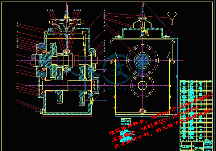
升速箱总成图.dwg

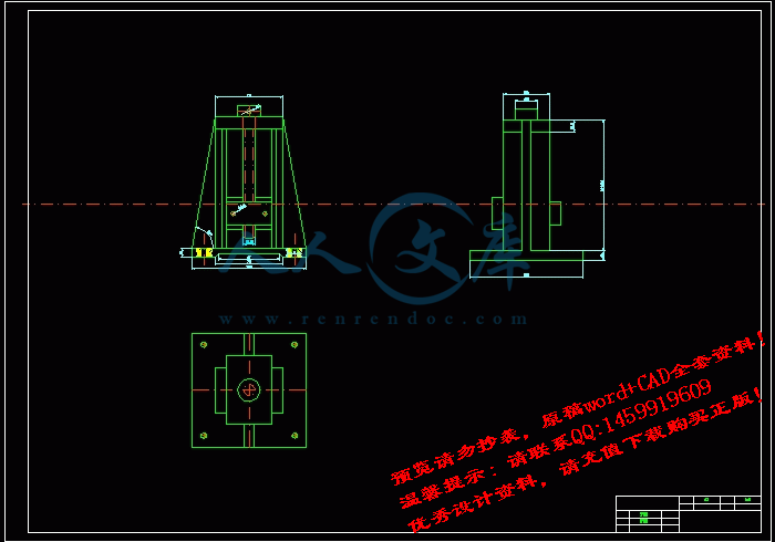
夹具.dwg

差速器和车桥--中英文翻译.doc

液压机械传动开式试验台设计.doc

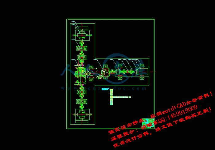
装配俯视图.dwg

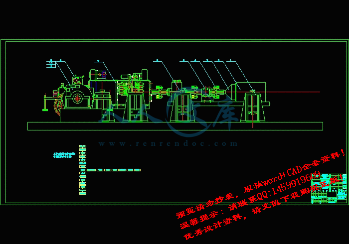
装配图.dwg

驾驶模拟器 防抱制动系统(ABS)--文献翻译.doc

液压机械传动开式试验台设计

任 务 书

设计(论文)题目液压机械传动系统开式试验台

主要研

究内容新型传动系统性能试验台;汽车、拖拉机燃油经济性的测试等。

试验台吸收功率:200KW,转速200~3000转/分

对试验台的试验原理进行设计,选择电涡流测功机为功率吸收装置和其他组件;设计或选择升速装置;

数据采集和处理利用车辆研究所开发的数据采集系统。

主要技

术指标(或研究目标)绘制实验台的总体布置图;对总体参数进行计算;

绘制总量不低于A0号的图纸3张,其中计算机图纸1张;

不低于12000字的设计计算说明书,10000外文字符资料翻译;

设计步骤:

①课题调研,查阅文献资料,明确设计任务;②选择设计方案;③总体设计④详细设计⑤撰写设计说明书;⑥毕业设计答辩。

进度计划①调查研究,熟悉设计内容,收集文献,时间占10%(约1周)

②实际任务分析与实施方案的确定,写出开题报告;时间占10%(约1周)

③实施设计、计算、绘图,论文起草时间占45%~50%(约5周)

④整理论文,时间占10%(约1周)

摘要

燃油经济性和较少的有害气体排放和日益增大的舒适性等要求是现代汽车十分重要的研究课题. 液压机械差速转向机构是利用液压机械无级传动原理,将液压传动与齿轮传动恰当组合的一种新型封闭双功率流传动机构。本文介绍了机——电——液一体化动态仿真试验台的系统结构及性能特点。讨论了系统的动态性能及恒转速控制的原理和基本规律。对部分试验和理论结果进行了分析和研究,分析了车辆动力传动试验台机械测功器的结构和工作原理,提出了机械测功器的控制方案,并进行了仿真计算。针对已有机械传动系统试验台存在的局限性提出了适合于不同传动形式及测试要求的多功能试验台的设计思路,对所涉及的多功能试验台的组成和工作原理进行了分析讨论,给出了不同组合形式时试验台结构及测试控制方法。计算表明,合理的选择可以使测功器获得较好的动态特性。试验结果表明该系统运行稳定、加载方便、节能效果显著,满足了设计的要求。

关键词: 车辆传动,动力传动试验台,性能分析,惯量模拟

Structure and performance Analysis of the Dynamic

Simulation Bench for Vehicle Transmission System

ABSTRACT

To satisfy the demand for greeted fuel economy, fewerem jssion and enhanced comfort, which are very important themes for modern automat boilers.The bydro-mechanical differential turning mechanism using hydro-mechanical infinite transmission theory is the new close double flow transmission mechanism being suitably made up of hydraulic transmission and gear transmission.This paper introduces the structure and performance characteristics of an integrated electro-hydro-mechanical control system of the dynamic simulation bench for vehicle transmission. The dynamic performance and the theory and basic law of the constant speed control are discussed.Some theoretical and experimental results are analyzed.The construction and working principles of a power-trans mission test bench and a mechanical dynamometer analyzed .Control policy about the mechanical dynamometer is described,then the matching method of the control system and the pivotal parameter are gained. Dynamic analysis of this model is finally demonstrated in detail。This paper analyses and discusses both composition of the multifunction test and operating principle,and presents test, method of cont to and structures of various combining test .A design idea of multifunction test bed is put forward which is suitable for different driving form and test requirement.The test results show that system runs steadily,saves energy remarkably,loads conveniently, andsatisfies requirement of design。

Keywords:  Vehicle transmission,Test bench,Performance analysis,Inertia simulat

前 言

近几年来,我国的工程车辆工业发展迅猛,而随着汽车工业的崛起也伴随着对于产品的实验与检测手段的落后。尤其是目前,我国制造汽车尚在起始阶段,还不成熟.但作为经济发展支柱的汽车工业,必然要在当今技术潮流中疾进,而以后汽车传动系统发展方向是以自动变速器技术(自动变速器和液压机械转向装置)为核心,所以为了给汽车自动传动产品完善设计理念、交检产品性能,控制产品的质量,提高汽车的品质,势必对其零部件提出更高更严格的要求。传动系是汽车实现发动机动力输出到行驶的必须系统,变速器是汽车传动系中一个重要总成,为了对变速器产品结构和零部件的性能、寿命进行测试和分析。为产品设计与质量评价提供可靠的科学依据,缩短产品的开发周期和提高产品质量;避免在用户使用中出现质量问题,减少售后服务的工作量,节约资金,降低成本,提高产品的市场信誉度。所以传动系统试验台的研究将为汽车、拖拉机的新技术改造提供试验平台,有力推动农业机械行业科研水平的提高具有特别重要的意义。

车辆传动系是车辆的重要组成部分,其作用不仅是为了实现减速(或者增速)、转换系统的运动传递路线、使各运动构件协调配合工作;同时还把原动机输出的功率和转矩传递到驱动轮、或者其它执行机构上克服行驶阻力或工作阻力而做功。实现传动路线、传动方向的转换和传递动力是车辆传动系的两个基本任务。

1传统系统结构介绍及功用

传统的履带式车辆传动系和汽车传动系相似,主要由用于切断动力的离合器、变换档位的变速器、起主要减速作用的主减速器、起差速作用的差速器、轮边差速及用于转向的轮边制动器组成;现代履带车辆传动系不断采用新技术、新结构,经过多年的发展和改进,逐步形成了现代履带车辆传动系。现代履带车辆传动系,将液压机械无级变速传动技术应用于变速机构取代了原来的离合器与固定轴式齿轮箱组成的变速机构,其中以双(多)功率流多段无级变速传动为代表;差速及转向装置由液压机械复合转向取代,形成主要由行星排和液压马达、液压泵组成的液压机械连续无级传动的复合转向。

液压机械无级变速传动以液压机械式无级自动变速器(HMT)为主,主要由多档自动变速器、液压变量泵和定量马达构成的液压变速装置、将机械和液压动力合成的行星齿轮机构三部分构成。液压机械传动是一种液压功率流与机械功率流并联的新型传动形式,通过机械传动实现传动高效率,通过液压传动与机械传动相结合实现机械传动无级变速。与传统的机械式变速器相比,液压机械式无级自动变速器有以下特点:

①能自动适应负荷和行驶阻力的变化,实现无级调速,保证发动机工作在最佳工作点,有利于提高其动力性、燃油经济性和工作效率。

②以液体为传力介质,使传动系动载大为减轻,易防止超载和发动机熄火,可大大提高有关零部件的寿命,对工作条件恶劣的农业机械和工程机械尤为重要。

③行驶平稳,能吸收衰减振动、冲击和噪声,提高乘坐舒适性。

④能以很低的车速稳定行驶,可提高坏路上的通过性和低速作业质量。

⑤操作轻便,便于实现换档自动化,降低驾驶员劳动强度。

⑥体积小,重量轻,惯性小,结构紧凑,节省材料,易于布置。

国外实际试验资料表明:装备无级自动变速器的拖拉机的作业性能显著提高,不仅能降低操作强度,提高车辆作业速度,改善作业质量,而且可以大幅度提高拖拉机的动力性和燃油经济性,统计对比数据表明生产效率提高12~16%,燃油消耗率降低8~10%,具有明显经济性,并减少了排放。

有此可见液压机械无级变速传动系统有着很广阔的市场,它不仅提高了工作效率,而且改善了驾驶员工作的环境。车辆传动试验台是对车辆传动系的主要传动部件和装置变速器、差速与转向部件等进行综合性能测试的试验设备。通过试验来检验传动装置设计的合理性,加工、制造、装配和调试的工艺性。对试验结果的深入分析有助于了解和评定传动部件和装置的综合机械性能,同时也为工程设计人员提供实践的参考资料和设计依据。随着车辆传动系向高速比、大功率、低噪声等方向的飞速发展,人们对于车辆传动系的性能提出了更高的要求,因此,对传动试验台的深入研究具有重要的实际应用意义。

         参考文献

[1] 刘惟信.《汽车设计》.清华大学出版社,2001年

[2] 张文春.《车辆传动试验台论证报告》 .河南科技大学 ,2004年

[3] 机械工程手册编辑委员会.《机械工程手册》.机械工业出版社,1997              

[4] 彭文生.《机械设计》.高等教育出版社,2003年          

[5] 刘惟信.张宁一.《汽车转向机构设计的研究》.北京汽车,1991

[6] 刘惟信,吴明常.《同步器优化设计的研究》.汽车工程,1990

[7] 李伟,刘惟信.《汽车四档变速器的设计》.当代汽车,1987

[8] 葛安林.《车辆自动变速理论与设计》北京:机械工业出版社,1993

[9] 刘惟信.《圆锥齿轮与双曲面齿轮传动》.北京:人民交通出版社出版,1993

[10] 刘惟信.《机械可靠性设计》北京:清华大学出版社,1994

[11] 陈家瑞.《汽车构造》.北京:人民交通出版社,1993

[12] 张洪欣.《汽车设计》.北京:机械工业出版社,1989

[13] 余志生.《汽车理论》.北京:机械工业出版社,1981

[14] 刘惟信,戈平,李伟.《汽车发动机与传动系参数最优匹配的研究》.汽车工程,1991

[15] 戈平,刘惟信.《汽车发动机与传动系的匹配分析和优化设计》.汽车技术,1993


内容简介:
DIFFERENTIAL AND REAR AXLES The differential is part of the rear-axle-housing assembly,which includes the differential,rear axles,wheels,and bearing. If the car were to be driven in a straight line without having to make turns,then no differential would be necessary.However,when the car rounds a turn,the outer wheel must travel farther than the inner wheel.The differential permits the two rear wheels to rotate different amounts when the car goes around a turn , while still delivering power to both rear wheels. The rear axles are attached to the wheels and have bevel side gears on their inner ends.The differential case is assembled on the left axle but can rotate on a bearing independently of the axle.The differential case supports the differential-pinion gear on a shaft,and this gear meshes with the two bevel gears.The fing gear is attached to the differential case so that the case rotates with the fing gear when the latter is driven by the drive pinion. The driving power enters the differential through the drive pinion on the end of the propeller shaft.The drive pinion is meshed with a large ring gear so that the ring gear revoves with the pinion. Attached to the ring gear is a differential-pinion shaft on which are assembled two differential-pinion gears.Each rear car wheel has a separate axle, and there are two side gears splined to the inner ends of the two wheel axles.The two side gears.When the car is on a straighet road ,the two differential-pinion gears do not rotate on the pinion shaft ,but they do exert pressure on the two side gears turn at the same speed as the ring gear ,causing both rear wheels to turn at the same speed,also. ntsWhen the car rounds a curve ,the outer wheel must turn faster than the inner wheel,To permit this,the two pinino gears rotate on their pinion shaft,transmitting more turning movement to the outer side gear that to the inner side gear.Thus,the side gear on the outer-wheel axle turns more rapidly than the side gear on the inner wheel axle.This permits the outer wheel to turn more rapidly while the car is rounding the curve. There are two basic types of axle:deed axles and live axle.The dead axle does not rotate; the wheel rotates on it.A common exmple is the axle on a horse-drawn wagon.Live axles are attached to the wheel so that both the wheel and the axle rotate together.Live axles are classified according to the manner in which they are supported:semifloating, three-quarer-floating,and full-floating.ntsAUTOMOBILE SYSTEM The fuel system has the job of supplying a combustible mixture of air and fuel to the engine. The fuel system must vary the proportions of air and fuel to suit different operating conditions. When the engine is cold, for example, then the mixture must be rich( have a high proportion of fuel) .The reason for this is that the fuel does not vaporize rapidly at low temperatures. Therefore, extra fuel must be added to the mixture so that there will be enough vaporized fuel to form a combustible mixture. The fuel system consists of the fuel tank, fuel pump, fuel filter, carburetor, intake manifold, and fuel lines, or tubes, connecting the tank, pump, and carburetor. Some gasoline engines use a fuel-injection system; in this system, a fuel-injection pump replaces the carburetor. The fuel tank, in which gasoline is stored, is normally located at the rear of the vehicle. It is made of sheet metal and is attached to the frame. A fuel pump delivers fuel from the tank to the carburetor. There are two general types of fuel pump, mechanical and electric. The fuel system has filters and prevent dire in the fuel from entering the fuel pump or carburetor. Dirt could, of course, prevent normal operation of these units and cause poor engine performance. The carburetor is essentially a mixing device which mixes liquid gasoline with air. In this process, it throws a fine spray of gasoline into air passing through the carburetor on its way to the engine. The gasoline vaporizes and mixes with the air to form a highly combustion chambers, where it is ignited. It burns, causing the engine to produce power. The mixture must be of varying degrees of rich nice to suit engine operating conditions. ntsIt must be rich( have a higher percentage of fuel) for starting, acceleration, and high-speed operation. And it should lean to( become less rich) for operation at intermediate speed with a worm engine. The carburetor has several different circuits, or passages, through which fuel and air-fuel mixture flow under different operating conditions to produce the varying richness of the air-fuel mixture. The purpose of the cooling system is to keep the engine at its most efficient operating temperature at all engine speeds and all drilling conditions. A great deal of heat is produced in the engine by the burning of the air-fuel mixture. Some of this heat escapes from the engine through the exhaust gases( the hot gases left after the gasoline is burned) . But enough remains in the engine to cause serious trouble unless removed by some other means. The cooling system takes care of this additional heat. The cooling system is built into the engine. There are hollow spaces around each engine cylinder and combustion chamber. These hollow spaces are called waterjackets, since they are filled with water. When the engine is running, the water takes heat from the engine, becoming hot in the process. A water pump pumps the hot water from the engine water jackets into the radiator. The radiator has two sets of passages. One set carries air( pulled through by car motion and the engine fan) . As the hot water passes through, it gives up its heat to the air passing through. The cooled water then reenters the engine, where it can pick up more heat. In operation, water continuously circulates between the engine and radiator, carrying heat from the engine temperatures are prevented. Two general types of cooling systems are used, air cooling and liquid cooling. The liquid cooling system consists of water pumps, water jackets, engine fan, radiator and so on. The water pump, driven by a belt from the engine crankshaft, circulates the cooling liquid between the radiator and ntsengine water jackets. The cooling liquid is water. Antifreeze compounds are added to the water during the winter. The water jacket are cast into the cylinder blocks and heats. The engine fan is usually mounted on the water-pump shaft and is driven by the same belt that drives the pump shaft and the generator. The purpose of the fan is to provide a powerful draft of air through the radiator. The radiator is a device for holding a large volume of air so that heat will transfer from the water to the air. The radiator core is divided into two separate compartments; water passes through one, and air passes through the other. The ignition system is part of the electric system of the automobile. Its purpose is to produce high-voltage surges( up to 20 000 volts) and to deliver them to the combustion chambers in the engine. These high-voltage surge surges then cause electric sparks in the combustion chambers. The sparks ignite, or set fire to, the air-fuel mixture in the combustion chambers so that it burns and cause the engine ton operate. The ignition system consists three basic parts: the ignition distributor, the ignition coil, and the spark plug, together with the connecting wires. When the engine is running, the ignition coil is repeatedly connected, it becomes loaded with electrical energy. Then, when it is disconnected, the “load” of electrical energy is released in a high-voltage. This surge flows through the wiring to the spark plug in the engine cylinder that is ready to fire. You must understand that all this takes place very rapidly. At high speed, the whole series of events happens in less than one three-hundredth of a second. That is, there will be as many as 300 of these events every second that the engine is running at high speed. Some systems use transistors to reduce the load on the distributor contract points. Other systems do not have contract points use instead a combination of transistors and a magnetic pick-up in the distributor. nts The ignition distributor has two jobs. First, it closes and opens the circuit between the battery and the ignition coil. The distributors second job is to distribute each high-voltage surge to the correct spark plug at the correct instant by means of the distributor rotor and cap and secondary wiring. There are two basic types of distributor: ( 1) the type using contact points to close and open the coil primary circuit; ( 2) the type using a magnetic pick-up and a transistor control unit to interrupt the current flow of the coil primary circuit. Automobile engines are not self-starts. In order to start them, the engine crankshaft must be turned over by some outside means so as to( a)admit air-fuel mixture to the cylinder, and( b) cause the mixture to fire. In the case of automobile engines, the mixture in the cylinder, after being compressed, must be not enough to ignite. This requires that the engine be turned over with sufficient speed. If the engine is turned over too slowly, the unavoidable small leaks past the piston rings and also through the intake and exhaust valves of four-circle engines will permit a substantial part of the fuel-air mixture to escape during the compression stroke. Also, the heat loss from the compressed air to the cylinder walls will be greater at low speed because of the longer exposure. The escape of air and the loss of heat both result in a lower temperature at the end of compression. Therefore, there is a minimum speed which the engine must attain before ignition will occur and the engine will begin firing. The starting speed depends upon the type and size of the engine, its condition, and the temperature of the air entering engine. The starting system contains a cranking, or starting, motor and other accessories. nts The starting motor electrically cranks the engine for starting. It is a special direct-current motor operating on battery voltage and is mounted on the engine flywheel house. The starter changes the electrical current into the mechanical energy to push the crank-shaft round. By means of this, the engine can be started. The cranking motor consists of the commutator end head, holding the brushes; the field frame, into which the field windings are assembled around pole shoes; the drive housing, which house the drive assembly and supports the motor on the engine flywheel housing; the armature; and the drive assembly. Some cranking motors also have a solenoid that operates the shift lever. Cranking-motor controls have varied from a simple foot-operated pedal to automatic devices that close the cranking-motor circuit when the accelerator pedal is depressed. The present system that has been almost universally adopted for passenger cars and many other vehicles has starting contacts in the ignition switch. When the ignition key is turned against spring pressure past the ON position to START, the starting contacts close. This connects the cranking-motor solenoid or magnetic switch to the battery. After the engine starts and the ignition key is released, spring pressure returns it to the ON position. The starting motor should not be operated more than 5 seconds during each starting operating, for the sake of recovering the energy of battery. It will not be allowed to start it again until its stopped for fifteen seconds. The manual transmission shown in Fig. 1 provides a means of varying the relationship between the speed of the engine and the speed of the wheels .Varying these gear ratios allows the right amount of engine power at many different speeds. Manual transmission requires use of a clutch to apply and remove the ntstorque to the transmission input shaft. The clutch allows this to happen gradually a so that the car can be started from a complete stop. Modern manual transmissions do not disengage any of the forward drive gears, they are simply connected to their shafts through the use of “ synchronizers” .Reverse is achieved reverse idler gears ,which are engaged to move the car backwards. Some manual transmissions have an “ overdrive” . An overdrive is a mechanical unit bolted to rear of the transmission. It is usually known as the fifth gear .When you use it, it will reduce the engine speed by about one-third ,which maintaining the same road speed. In an automatic transmission, gear ratios are changed automatically. This eliminates the need for the driver to operate the clutch and manually “ shift gears.” The typical automatic transmission combines a fluid torque converter , a planetary-gear system, and a hydraulic control system in a single unit. As car speed changes , various gear ratios between the crankshaft and the wheels are selected and then changed automatically. Automatic controls inside the transmission supply the proper ratio for the driving condition. In addition to the forward-gear ratios, neutral, and reverse, the automatic transmission has a PAPK position. This locks the transmission to prevent the car from moving or rolling away while parked. nts差速器和车桥 差速器和后桥壳总成的一个部件,后桥壳总成包括差速器、后桥、车轮和轴承。 如果汽车按直线行驶,就不需要差速器了。然而,当汽车转弯时,外测的车轮一定比内测的车轮行驶更长的距离。差速器可在汽车转弯时使两个后车轮以不同的转速转动,同时还向两个后轮提供动力。 后桥与车轮相连,内端装有一个半轴齿轮。差速器壳支承在左侧车桥上,而且能够在轴承上做独立转动。差速器壳支承在行星齿轮轴上,行星齿轮与两个半轴齿轮相啮合。冠状齿轮与差速器壳 相连,这样当冠状齿轮由传动齿轮驱动转动时,差速器壳也在转动。 也就是说,驱动力是从传动轴末端的传动齿轮输送到差速器的。传动齿轮与一个很大的冠状齿轮啮合,传动齿轮驱动冠状齿轮。 冠状齿轮与差速器齿轮轴相连,差速器齿轮轴上装有两个行星齿轮。每个后车轮都有一个独立的车桥,两个半轴齿轮用花键与两个车轴的内端相连。两个行星齿轮与这两个齿轮相啮合。当汽车直驶时,两个行星齿轮不在齿轮轴上转动,但却向两个半轴齿轮传递动力,这样半轴齿轮与冠状齿轮的转速相等,从而使两个后轮也以同样的速度转动。 当汽车转弯时,外测车轮就必须比内 侧车轮转的更快。为了达到这一目的,两个行星齿轮在齿轮轴上转动,给外侧的车轮提供比内侧的车轮更多的运动,这样外侧车轮轴上的半轴齿轮比内侧车轮轴上的半轴齿轮转动更快,nts这样,当汽车转弯时,外侧车轮就转的更快些。 车桥有两种基本形式:非断开式和断开式。非断开式车桥不转动,而车轮在车桥上转动。最常见的例子就是在马车上所见到的非断开式车桥,断开式车桥与车轮相连,这样两者一起转动。断开式车桥根据其承载可分为:半浮动,四分之三浮动和全浮动。nts 汽 车 系 统 发动机的燃油系统: 燃料供给系统的作用是向 发动机提供由空气和燃料所组成的可燃混合气。燃料系统必须改变空气和燃料的比例以适应不同的运行状态。例如,当发动机冷车时,就必须提供较浓的混和气(具有较高的燃油比例)。这是因为在低温下燃油不能迅速汽化,因此,要在混合气中额外增加燃油,这样才有足够汽化燃料形成可燃混合气。 燃料系包括汽油箱、汽油泵、汽油滤清器、化油器、进气歧管以及连接油箱、油泵和化油器的油管。有的汽油发动机使用的是一套燃油喷射系统,在这一系统中,燃油喷射泵取代了化油器。 汽油箱用来储存汽油,通常安装在汽车的后部。油箱由金属板制成,固定在车架上。 油泵把油箱的燃油抽出送到化油器中。通用的油泵有两种 : 机械泵和电子泵。燃油系统装有滤清器和过滤网,防止燃油的杂物进入燃油泵和化油器。否则,污物会影响这些部件的正常运转,并引起发动机运转不良。 化油器实际上是一个把液体燃油与空气相混合的混合气形成装置。在这一过程中,化油器把燃油以雾状喷入流经化油器得空气中,然后进入发动机。雾化燃油和空气形成高度易燃的混合气。可燃混合气进入发动机的燃烧室,并在那里被点燃。可燃混合气燃烧,使发动机产生动力。混合气的浓度比例可以改变,以适应发动机的运行状况。汽车在启动、加速和高速行驶nts时,需要含油浓度较高的混合气;热状态下的发动机中速行驶时,混合气含燃油浓度则可低一些。化油器有几个不同的供油系统和通道,通过这些供油系统,再不同的行驶状态下,可提供不同的可燃混合气。 发动机冷却系统: 冷却系统的作用是控制发动机在各种转速和各种行驶状态下都能有效的控制温度。 混合气的燃烧在发动机中产生大量的热,其中部分热量通过废气排除。是,残留在发动机中的余热仍足以使发动机受到严重损坏,除非用其他方法排除这些余热,冷却系统就是专门消除这些余热的。 冷却系统就设置在发动机中。在每个气缸体和燃烧室周围都留有空腔 。这些空腔装满了水,因此
温馨提示:
1: 本站所有资源如无特殊说明,都需要本地电脑安装OFFICE2007和PDF阅读器。图纸软件为CAD,CAXA,PROE,UG,SolidWorks等.压缩文件请下载最新的WinRAR软件解压。
2: 本站的文档不包含任何第三方提供的附件图纸等,如果需要附件,请联系上传者。文件的所有权益归上传用户所有。
3.本站RAR压缩包中若带图纸,网页内容里面会有图纸预览,若没有图纸预览就没有图纸。
4. 未经权益所有人同意不得将文件中的内容挪作商业或盈利用途。
5. 人人文库网仅提供信息存储空间,仅对用户上传内容的表现方式做保护处理,对用户上传分享的文档内容本身不做任何修改或编辑,并不能对任何下载内容负责。
6. 下载文件中如有侵权或不适当内容,请与我们联系,我们立即纠正。
7. 本站不保证下载资源的准确性、安全性和完整性, 同时也不承担用户因使用这些下载资源对自己和他人造成任何形式的伤害或损失。
提示  人人文库网所有资源均是用户自行上传分享,仅供网友学习交流,未经上传用户书面授权,请勿作他用。
关于本文
本文标题:液压机械传动开式试验台的设计【优秀试验台全套课程毕业设计含4张CAD图纸】
链接地址:https://www.renrendoc.com/p-475078.html

官方联系方式

2:不支持迅雷下载,请使用浏览器下载   
3:不支持QQ浏览器下载,请用其他浏览器   
4:下载后的文档和图纸-无水印   
5:文档经过压缩,下载后原文更清晰   
关于我们 - 网站声明 - 网站地图 - 资源地图 - 友情链接 - 网站客服 - 联系我们

网站客服QQ:2881952447     

copyright@ 2020-2025  renrendoc.com 人人文库版权所有   联系电话:400-852-1180

备案号:蜀ICP备2022000484号-2       经营许可证: 川B2-20220663       公网安备川公网安备: 51019002004831号

本站为文档C2C交易模式,即用户上传的文档直接被用户下载,本站只是中间服务平台,本站所有文档下载所得的收益归上传人(含作者)所有。人人文库网仅提供信息存储空间,仅对用户上传内容的表现方式做保护处理,对上载内容本身不做任何修改或编辑。若文档所含内容侵犯了您的版权或隐私,请立即通知人人文库网,我们立即给予删除!