表格.doc

履带拖拉机中央传动及转向离合器的设计【优秀离合器全套课程毕业设计含4张CAD图纸】

收藏

压缩包内文档预览:
预览图 预览图
编号:475088    类型:共享资源    大小:7.24MB    格式:RAR    上传时间:2015-08-29 上传人:QQ14****9609 IP属地:陕西
40
积分
关 键 词:
履带拖拉机 中央传动 转向离合器 离合器设计 离合器 课程毕业设计 履带拖拉机中央传动及转向离合器的设计
资源描述:

中央传动及转向离合器设计

履带拖拉机中央传动及转向离合器的设计【优秀离合器全套课程毕业设计含4张CAD图纸】

【带任务书+开题报告+外文翻译】【34页@正文8900字】【详情如下】【需要咨询购买全套设计请加QQ1459919609】

任务书.doc

参考文献资料

大锥齿轮.dwg

封皮1.doc

履带拖拉机中央传动及转向离合器设计.doc

开题报告.doc

总装图.dwg

摘要.doc

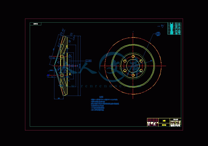
摩擦片总成.dwg

电力机车简介--中英文翻译.doc

目 录.doc

转向离合器总成.dwg

任务书

设计(论文)题目352履带拖拉机-中央传动及转向离合器设计

主要研究课题主要研究352履带拖拉机中央传动及转向离合器基本结构与设计方法。参照国内外拖拉机中央传动及转向离合器的基本参数,查阅有关资料,完成352履带拖拉机中央传动及转向离合器的性能计算与基本结构设计。

主要技术指标(或研究目标)

352履带拖拉机的基本参数:发动机功率25.8Kw,发动机转速2000r/min,整机速度范围2~10Km/h,整机使用重量3.5t,履带板节距125mm。

完成中央传动及转向离合器的设计计算,绘制中央传动及转向离合器装配图,完成总和不少于3张零号图纸的结构设计图、装配图和零件图,其中应包括计算机绘制的具有中等难度的1号图纸一张以上。

  按要求格式独立撰写不少于12000字的设计说明书,全部用计算机打印(编排要求到河南科技大学网站查:毕业设计说明书(论文)的格式规定),查阅与课题相关的文献资料15篇以上,应有中英文摘要,独立完成10000以上印刷符号的外语译文。

中央传动及转向离合器设计

摘要

中央传动用来增加传动系的传动比,以达到减速增扭的目的,通常还用来改变转矩的传递方向,使转矩从纵置的变速箱输出轴传递给横置的中央传动两侧输出轴。

中央传动应有适当的传动比,以保证拖拉机具有良好的牵引性与经济性;结构应紧凑,以减小后桥尺寸和和质量,保证后桥有足够的离地间隙;齿轮装置应有足够的承载能力和支承刚度,如系锥齿轮副,则还应便于调整。

中央传动的齿轮形式目前主要有圆柱齿轮和圆锥齿轮。圆柱齿轮结构简单,加工较容易,在传动时不致产生轴向力。但仅适用于采用横置变速箱的拖拉机。而圆锥齿轮应用则较为广泛。

履带拖拉机在行使过程中,需要经常改变行驶方向,这就需要有一套能够按照司机意志来改变或恢复拖拉机行驶方向的专设机构,它将司机踩下转向离合器踏板的动作转变为车轮的偏转动作,这就是所谓的转向系统。转向性能是保证车辆安全,减轻驾驶员劳动强度和提高作业效率的重要因素。

转向离合器转向系统由于构造简单,制造方便,维修容易,在拖拉机上广泛采用。它具有转向半径小,直线行驶性好等优点。但由于传递的转矩较大,只得采用多片式离合器,而多片式离合器分离彻底性比较差。这对转向离合器来说,除了使摩擦面的磨损略微增大外,对整机性能没有太大影响,不像主离合器分离不彻底会造成换档困难。

关键词:中央传动,转向离合器,锥齿轮,转向系统

目 录

第一章 前 言1

第二章 中央传动及转向离合器概论3

§2.1 履带拖拉机转向机构概述3

§2.2 中央传动的概述4

第三章 中央传动及转向离合器方案分析5

§3.1 转向离合器方案分析5

§3.2 中央传动方案分析10

第四章 转向系统设计计算 14

§4.1 螺旋锥齿轮的计算14

§4.2 转向离合器设计计算17

§4.3 带式制动器的设计计算19

第五章 主要零件的强度校核与计算21

§5.1 螺旋锥齿轮的承载能力计算21

§5.2 轴强度计算22

§5.3轴承寿命计算24

第六章 结 论28

致 谢29

参考文献30

第一章 前 言

拖拉机的主要任务是用来拖带农机具进行各种田间作业(如翻地、播种、中耕等);也可作为其他农业机械(如脱谷机、扬场机等)的动力;另外拖带拖车可进行运输作业。为适应农业生产中各项作业的需要,拖拉机分有履带式和轮式两种。

履带式拖拉机的特点是行走部分与地面的接触面积大,压强小,对土壤压实的作用小,而且不易打滑,可以在湿度较大的土壤上进行作业。一般履带式拖拉机的离地间隙小而功率大,适用于大面积的翻地、播种等主要农业作业。如东方红-54和75拖拉机。

参考文献

[1]王望予  .汽车设计. 北京:机械工业出版社, 2004.8

[2]臧杰 , 阎岩.汽车构造.下册 北京:机械工业出版社, 2005.8

[3]张文春 .汽车理论.北京:机械工业出版社, 2005.7

[4]甘永立 .几何量公差与检测.上海:上海科学技术出版社, 2004.7

[5] 辽宁省农业机械化学校《拖拉机构造》北京:机械工业出版社,1972.10

[6]王昆  何小柏 .机械设计课程设计.北京:高等教育出版社, 1996

[7]吉林工业大学拖拉机考研室.拖拉机构造.下册 北京:机械工业出版社, 1972.10

[8][苏] 李沃夫斯基.拖拉机传动装置. 北京:中国农业机械出版社, 1979.3

[9]濮良贵  纪名刚 .机械设计.第七版 北京:高等教育出版社, 2001

[10]孙桓  陈作模  .机械原理.第六版 北京:高等教育出版社, 2000.8

[11]第一机械工业部机械研究院农业机械研究所.农业机械设计手册.北京:机械工业出版,  1972.2

[12]文九巴.机械工程材料.北京:机械工业出版社, 2002.7

[13]侯洪生  .机械工程图学.北京:科学出版社, 2001

[14]刘鸿义  .简明材料力学.北京:高等教育出版社, 1997

[15]徐灏 .机械设计手册.北京:机械工业出版社 , 1991


内容简介:
毕 业 设 计 ( 论 文 ) 任 务 书 (指导老师填表) 填表时间: 2007 年 3 月 6 日 教研所(教研室)主任签字: 07 年 3 月 7 日 学生姓名 丁亚东 专业 班级 车辆 032 指导老师 陈凤涛 课题类型 工程设计 设计(论文)题目 352 履带拖拉机中央传动及转向离合器 设计 主要研 究课题 主要研究 352 履带拖拉机中央传动及转向离合器 基本结构与设计方法。参照国内外拖拉机 中央传动及转向离合器 的基本参数,查阅有关资料,完成 352 履带拖拉机 中央传动及转向离合器 的性能计算与基本结构设计。 主要技 术指标 (或研究 目标) 352 履带拖拉机的基本参数:发动机功率 25.8Kw,发动机转速 2000r/min,整机速度范围 2 10Km/h,整机使用重量 3.5t,履带板节距 125mm。 完成 中央传动及转向离合器的 设计计算,绘制 中央传动及转向离合器 装配图,完成总和不少于 3张零号 图纸的结构设计图、装配图和零件图,其中应包括计算机绘制的具有中等难度的 1 号图纸一张以上。 按要求格式独立撰写不少于 12000 字的设计说明书,全部用计算机打印(编排要求到河南科技大学网站查:毕业设计说明书(论文)的格式规定 ),查阅与课题相关的文献资料 15 篇以上,应有中英文摘要,独立完成 10000 以上印刷符号的外语译文。 进度计划 ( 5 周) 调研,搜集、分析资料; ( 6 周) 全组集体讨论,制定、确定总体方案; ( 7-10 周) 完成主要总图设计; ( 11-14 周) 完成零、部件图设计说明书; ( 15 周) 整理图纸及全部设计文件,最后交卷; ( 16 周) 审核、互审评阅设计; ( 17 周) 答辩,评定成绩。 主要参 考文献 拖拉机构造 ; 拖拉机理论; 拖拉机设计; 拖拉机设计手册 ; 有关拖拉机行业杂志、网站。 机械零件设计手册 nts Introduction to Locmotive A locomotive is a railway vehicle that provides the motive power for a train,and has nohy detached from their trains, are known as power cars. Traditionally,locomotive hual their trains. Increasingly common these days in passenger service is push-pull operation,where the locomotive push the trains in one direction and are controled from a control cab at the opposite end of the train in the other. Beniefits of locomotives There are many reasons why the motive power for trains has been traditonally isolated in a locmotive,rather than is self-propelled vehicles.these include: Ease of maintenance it is easier to maintain one locomotive than many self-propelled cars. Safety it is often safer to locate the trains power system away from passenger. This was particularly the case for the steam locomtive,but still has some relevance. Easy replacement of motive power should the locomotive break down, it is easy to replace it with a new one . Failure of the motive power unit does not require taking the whoole train out of service. Efficiency idle trains do not waste expensive motive power resources. Separate locomotives mean that the costly motive power assets can be moved around as needed. Obsolescence cycles separating the motive power from the payload-hauling cars means that either can be replaced without affecting the other. At some times, locomotive have become obsolete when their cars are not, or vice versa. Electric Locomotives The electric locomotive is supplied externally with electric power, either through an overhead pickup or through a third-rail. While the cost of electrifying track is rather high, electric trains and locomotives are significantly cheaper to run than diesel ones, and are capable of superior acceleration as well as regenerative braking, making them ideal for passenger service in densely populated areas. Almost all high speed train systems(e.g.IEC,TGV, bullet train) use electric power, because the power needed for such performance is not easily carried on board. Fot example the most powerfu electric locomotives that are used today on the channel tunnel freight services use 7Mwatts of power. The first known electric locomotive was buit by a Scotsman, Roert Davidson of Aberdeen in 1837 and was powered by galvanic cells. Modern electric locomotive range from small battery-powered machines for use in mines to large main-line locomotives of 6,000 horsepower(4.5MW) or more. In reality most modern locomotives are electricaly driven. Pure electric locomotives take their electrical supply from an external source while diesel-electric locomotives carry their own generating station. nts Main line electric locomotives first appeared at the beginning of the 20th century.The reason for their introduction was the problem of smoke, especially in tunnlels caused by steam locomotives. In the UK this was the London underground system while in the USA, it was under river tunnles and needs to eliminate smoke in built up areas. Early electric locomotives all relied on external power sourcing. Once up and running they tend to be reliable and efficint, but the supply infrastructure is a large capital expense that does require ongoing maintenance. For this reason only heavily used lines could justify electrification. For suburban lines the reduction in pollution from steam locomotives was a benefit all were aware ofl The world speed record for a wheeled train was set in 1990 ba a French TGV which reached a speed of 515.3km/h (320mph). While recently designed electrififed railway systems invariably operate on alternating current, many existing direct current sytems are still in use e.g. in South Africa,Spain,and the United Kingdom(750v and 1500v); Netherlands(1500v); Belgiu, Italy, Poland (3000 v), and the cites of Mumbia and Chicagio (which will be switched to AC by 2025). Early locomotives came in a variety of forms. Generally they were designed to run off the supplied current. so locomotives with a direct current (DC) supply had DC motors while a alterntating current(AC) supplied locomotives with AC motors. AC can be either single or three phase. While the former requies two wire supply, one overhead the other being the track, three phase require three supply wire.Three phase locomotives therefore had two overhead supplies,the track being the third. DC supplies were either overhead or by means of a track level supply, commonly called the third rail. AC traction motors tended to be smaller than DC motors. This often meant electric locomotives with steam engine type cranks. DC motors could be smaller and set up to drive the axles.usually through a gear ,but in some early examples by being part of the axle. Even so, some notable DC electric locomotives had large DC motors driving large driving wheels. One possibility with electric locomotives is that the motor can be used as a generator during braking, feeding electricity back into the supply system; this is called regenerative barking. This is not a new idea, it was one reason for the adoption by some railways of 3 phase AC suppies. Especially in mountainous aresa where the locomotive going down would generate much of the suppy for a locomotive going up. The Swiss railway uses the system; three modern locomotives heading downwards generate enough power to power a single locomotive in its upward journey. Today all eclctric locomotives tend to have drive motors close to the axles, although some still have the motor in the body driving the wheels through internal drive shafts. Modern solid state electrical control systems means the motor does not need to match the supply. This meams multi-voltage cross border locomotives are now quite nts common. Drive motors are generally DC, but there are 3 phase motors on some locomotives. A small number of electric locomotives can also operate off batery power to enable short journeys or shuting to occur on non-electrified lines or yards. Pure battery locomotives also found usage in mines and other underground workings where diesel fumes or smoke are not safe aand where external electricity supplies could not be used. Battery locomotives are also used on many underground railways for maintenance operations as they are required to operate in areas where the electricity supply has been temmporarily disconnected. Parts of Electric Locomotive Awynchronoux Motor Modern traction motor type using three phase AC electrical supply and now the favoured deisgn for modern train traction systems . Can be used on DC and AC electrified. railways with suitable control electronics and on diesel-electric locomtives. Axle Brush The means by which the power supply ciruit is completed with the substation once power has been drawn on the locomotive. Current collected from the overhead line or third rail is returned via the axle brush and one of the running rails. Battery All trains are provided with a battery to provide start up current for supplying essential circuitts, such as emergency lighting ,when the line supply fails. The battery is usually connected across the DC control supply circuit. Circuit Breaker An electric train is almost always provied with some sort of circuit breaker to isolate the power supply when there is a fault, or for maintenance. On AC systems they are usually on the roof near the pantograph. There are two types-the air blast circuit breaker and the vacuum circuit breaker or VCB. The air or vacuum part is used to extinguish the arc which occurs as the two tips of the circuit breaker are opened. The VCB is popular in the UK and the air blast circuit breaker is more often seen on the continent of Europe. Converter Generic term for any solid state electronic system for converting alternating current to direct current or vice versa. Where an AC supply has to be converted to DC it is called a rectifier and where DC is converted to AC it is called an inverter. The word originated in the US but is now common elsewhere. Cooling Fans To keep the thyristors and other electronic power systems cool, the interior of a modern locomotive is equipped with an air management system, electronically controlled to keep all systems operating at the correct temperature. The fans are powered by an auxiliary inverter producing 3-phase AC at about 400 volts. nts DC link Used on modern electronic power systems between the single phase rectifier and the 3-phase inverter. It is easier to convert the single phase AC from the overheak line to the 3-phase required for the motors by rectifying it to DC and then inverting the DC to 3-phase AC. Inverter Electronic power device mounted on trains to provide alternating current from direct current. Popular nowadays for DC railways to allow three phase drive or for auxiliary supplies which need an AC supply. Line Breaker Electro-mechanical switch in a traction motor power circuit used to active or disable the circuit the circuit. It is nomally closed to start the train and remains closed all the time power is required. It is opened by a command from the driving controller,no-volts detected, overload detected and (were required) wheel spin or slide detected. It is linked to the overload and no-volt control circuits so that it actually functions as a protective circuit breaker. Master Controller Drivers power control device located in the cab. The driver moves the handle of the master controller to apply or reduce power to the locomotive or train. Motor Blowers Traction motors on electric locomotives get very hot and to keep their temperature at a reasonable level for long periods of hard word, they are usually fitted with electric fans called motor blowers. On a modern locomotive,they are powered by an auxiliary 3-phase AC supply of around 400 volts supplied by an auxiliary inverter. Rectifer A converter consisting of thyristors and diodes which is used to convert AC to DC. A modern locomotive will usually have at least two, one for the power circuits and one or more for the auxiliary circuits. Synchronous Motor Traction motor where the field coils are mounted on the drive shaft and the armature coils in the housing, the inverse of normal practice.Favoured by the French and used on the high speed TGV Atlantique trains, this is a single-phase machine controlled by simple inverter. Now superseded by the asynchronous motor. Transformer A set of windings with a magnetic core used to step down or step up a voltage from one level to another.The voltage differences are determined by the proportion of windings in the input side compared with the proportion on the output side. An essential requirement for locomotives and trains using AC power, where the line voltage has to be stepped down before use on the train. Equipment Layout Ventilation System Equipment layout and ventilation systems 设备布置和通风系统设计 Equipment layout and design of the ventilation system nts nts 河 南 科 技 大 学 毕 业 设 计(论 文) 题目 352 履带拖拉机中央传动及转向离合器 设计 姓 名 丁 亚东 院 系 车 动 学 院 专 业 车 辆 工 程 指导教师 陈 凤 涛 2007 年 5 月 15 日 nts毕业设计(论文)包含内容及装订顺序 1. 毕业设计(论文)任务书 2. 中英文摘要(含关键词) 3. 目录 4. 前言 5. 正文 6. 结论 7. 参考文献 8. 致谢 9. 附录 10. 外文资料译文 nts1 中央传动及转向离合器设计 摘要 中央传动用来增加传动系的传动比 ,以达到减速增扭的目的 ,通常还用来改变转矩的传递方向 ,使转矩从纵置的变速箱输出轴传递给横置的中央传动两侧输出轴。 中央传动应有适当的传动比 ,以保证拖拉机具有良好的牵引性与经济性 ;结构应紧凑 ,以减小后桥尺寸和和质量 ,保证后桥有足够的离地间隙;齿轮装置应有足够的承载能力和支承刚度 ,如系锥齿轮副 ,则还应便于调整。 中央传动的齿轮形式目前主要有圆柱齿轮和圆锥齿轮。圆柱齿轮结构简单 ,加工较容易 ,在传动时不致产生轴向力。但仅适用于采用横置变速箱的拖拉机。而圆 锥齿轮应用则较为广泛。 履带拖拉机在行使过程中,需要经常改变行驶方向,这就需要有一套能够按照司机意志来改变或恢复拖拉机行驶方向的专设机构,它将司机踩下转向离合器踏板的动作转变为车轮的偏转动作,这就是所谓的转向系统。转向性能是保证车辆安全,减轻驾驶员劳动强度和提高作业效率的重要因素。 转向离合器转向系统由于构造简单,制造方便,维修容易,在拖拉机上广泛采用。它具有转向半径小,直线行驶性好等优点。但由于传递的转矩较大,只得采用多片式离合器,而多片式离合器分离彻底性比较差。这对转向离合器来说,除了使摩擦面的磨损略微 增大外,对整机性能没有太大影响,不像主离合器分离不彻底会造成换档困难。 关键词 :中央传动,转向离合器,锥齿轮,转向系统 nts2 CENTRAL SPREAD TO MOVE AND ATEERING MECHANISM DESIGN ABSTRACT Central spread to use to increase to spread to move to fasten of spread and move ratio, the purpose that to attain to decelerate to increase to twist, usually return to use to change the torque to deliver the direction, make torque place become soon the box outputs the stalk to deliver to horizontal place central to spread to move the two sides exportation stalk. Central spread to move and should have appropriate of spread and move ratio, with the assurance that the tractor has to lead the sex and economy goodly; structure should tightly packed, after to let up the bridge size and and quantity, the assurance is behind the bridge has to leave a ground of cleft enough;The wheel gear device should have the enough loading ability and pay to accept just degree, return if department the bevel gears is vice, should easy to adjustment. Central spread the dynamic wheel gear form to mainly have the cylinder wheel gear and the bevel gearses currently.The cylinder wheel gear structure is simple, processing to compare easily, produce the stalk toward dint unlikely while spread move.But be applicable to the adoption only horizontal place to become soon the tractor of the box.But the cone wheel gear the application then compare extensively. The track tractor professional makes in the process, needing to usually change to drive the direction, this need to be have a set of can change or recover the tractor to drive the particularly establish of the direction organization according to the driver will, it deflect the action change that the driver tramples bottom to change direction the clutch pedal for the felloe action, this is to change direction the system so calledly.Change direction the function is to guarantee the vehicle safety, easing the pilot the labor strength and raise important factor of the homework efficiency. steering mechanism changes direction the system because of structure in brief, make convenience, maintain easily, in the dalliance on board extensive nts3 doption.It has the radius of change direction small, drive sex good etc. advantage straightly.But because the torque that deliver compare greatly, have to several type clutches of adoption, but several types clutch separate thoroughly sex is worse.This says towards steering mechanismcome, in addition to making rub to face of wearing away the inching aggrandizement, having no to the whole machine function to affect too greatly, be unlike the main clutch separation ill success and will result in shift gear the difficulty. KEY WORDS: Central spread to move , steering mechanism ,bevel gears, the steering system nts4 目 录 第一章 前 言 1 第二章 中央传动及转向离合器概论 3 2.1 履带拖拉机转向机构概述 3 2.2 中央传动 的概述 4 第三章 中央传动及转向离合器方案分析 5 3.1 转向离合器方案分析 5 3.2 中央传动方案分析 10 第四章 转向系统设计计算 14 4.1 螺旋锥齿轮的计算 14 4.2 转向离合器设计计算 17 4.3 带式制动器的设计计算 19 第五章 主要零件的强度校核与计算 21 5.1 螺旋锥齿轮的承载能力计算 21 5.2 轴强度计算 22 5.3 轴承寿命计算 24 第六章 结 论 28 致 谢 29 参考文献 30 nts5 第一章 前 言 拖拉机的主要任务是用来拖带农机具进 行各种田间作业(如翻地、播种、中耕等);也可作为其他农业机械(如脱谷机、扬场机等)的动力;另外拖带拖车可进行运输作业。为适应农业生产中各项作业的需要,拖拉机分有履带式和轮式两种。 履带式拖拉机的特点是行走部分与地面的接触面积大,压强小,对土壤压实的作用小,而且不易打滑,可以在湿度较大的土壤上进行作业。一般履带式拖拉机的离地间隙小而功率大,适用于大面积的翻地、播种等主要农业作业。如东方红 54 和 75 拖拉机。 拖拉机基本上是由发动机、传动装置、车架和行走装置、操纵装置、工作装置和电气设备等六部分组成。传动装置的 功用是将发动机的动力传递给行走装置或其他工作装置;在驾驶员的操纵下,使拖拉机起步;停车;改变牵引力或行进方向,它包括离合器、变速箱、中央传动和最终传动等。如下图所示。 图 1-1 履带拖拉机传动系简图 1离合器 2联轴节 3变速箱 4中央传动 5转向离合器 6制动器 7最终传动 8动力输出轴 本毕业设计说明书,主要讲述了最终传动的选择设计和方案分析。对最终传动的分类和工作原理进行了深入的对比和分析,选出最优方案来进行设计,选择合适的机构和零件。这次设计是在以往所学基础和专业课程的基础上设计的 ,经过对比其他车型同类装置的设计方案,有选择的借鉴或创新来进行设计。 nts6 由于本书编写时间仓促,编者水平有限,难免有漏洞,诚恳的希望老师和同学批评指正。 nts7 第二章 中央传动及转向离合器概论 2.1 履带拖拉机转向机构概述 履带拖拉机转向机构用来改变驱动力在两侧履带上的分配 (包括改变方向 ),造成转向力矩以实现拖拉机转向。 履带拖拉机转向机构可按不同特征分类 : ( 1)按转向时的速度分 1) 转向时平均速度不变 ,即对称面上的 A 点的速度和直线行使时速度 错误 !未找到引用源。 相等 (如图 a 所示 ),所有差速 器式转向机构 (单差速器、双差速器、差速器式双功率流转向机构 )都属于这一类。 快速侧履带的纵向对称面 B点 (如图 b 所示 )的速度等于 错误 !未找到引用源。 。 转向离合器、单级和多级行星式 (包括双功率流 )转向机构属于这一类。快速侧、慢速侧履带对称面上的 B、 C 点 (如图 c 所示 )的速度均低于 错误 !未找到引用源。 ,有些采用电传动的坦克即速车辆属于这一类。 图 2-1 履带拖拉机转向时速度的改变 1 外侧履带 2 外侧履带 (2) 按固定转向半径的大小和数目分 固定转向半径 ,是指两侧履带各按指定的 速度转向时形成的转向半nts8 径 ,这里所谓的 “ 指定的 ” 是指可由人准确控制的、不包括驱动轮被切断动力后被机体推着前进的各种速度。 1) 具有一个固定的转向半径 R,R=0.5B(B 为轨距 ),转向离合器、单级行星转向机构属此。 2) 具有一个固定的转向半径 R,R 错误 !未找到引用源。 0.5B,双差速器属于此类。 3) 具有两个固定转向半径 ,其中一个等于 0.5B,另一个大于 0.5B,两速行星转向机构属此。 4) 变速箱每换一个档 ,就有相应的固定转向半径。 5) 具有无级变化的转向半径。 (3)按功率流传递的方式 , 可分为单功率流 (发动机功率同时通过 单一途径传给每侧驱动轮 )转向机构 ,和双功率流 (发动机同时通过两条途径传给每侧驱动轮 )转向机构。 从上面的分类看 ,转向机构种类繁多 ,履带拖拉机实际上广泛采用的是单功率流转向机构。例如 :转向离合器、双差速器、单级或双级行星机构。至于原地转向机构和两侧单独变速的转向机构也有采用。 除具有一般要求如结构简单可靠、操纵灵活、轻便、维修方便、使用寿命长等外 ,还应满足下面要求 : 拖拉机直线行驶稳定性好。 转向时对发动机产生的附加载荷小。 尽可能保证拖拉机平顺而迅速地由直线运动过渡到给定直线半径的曲线运动。 最小最 小半径应尽可能小。 转向机构在拖拉机后桥占有的横向尺寸应小。 1.2 拖拉机中央传动的概述 中央传动用来增加传动系的传动比 ,以达到减速增扭的目的 ,通常还用来改变转矩的传递方向 ,使转矩从纵置的变速箱输出轴传递给横置的中央传动两侧输出轴。 中央传动应有适当的传动比 ,以保证拖拉机具有良好的牵引性与经济性 ;结构应紧凑 ,以减小后桥尺寸和和质量 ,保证后桥有足够的离地间隙;齿轮装置应有足够的承载能力和支承刚度 ,如系锥齿轮副 ,则还应便于调整。中央传动的齿轮形式目前主要有圆柱齿轮和圆锥齿轮。圆柱齿轮结构简单 ,加工较容易 ,在传动时不致产生轴向力。但仅适用于采用横置变速箱的拖拉机。而圆锥nts9 齿轮应用则较为广泛。 第三章 中央传动及转向离合器方案分析 2.1 转向离合器方案分析 1 转向离合器多采用多片式摩擦离合器,靠摩擦表面的摩擦力来传递转矩。当分离某一侧的离合器时,就可以减小或切断该侧驱动轮所传转矩,使拖拉机转向。 1)按摩擦表面的工作条件可分为干式和湿式两类 ,本方案根据参考车型采用干式。 2)按压紧和分离摩擦片的方式可分为: 弹簧压紧,杠杆 (或凸轮 )机构分离。 弹簧压紧,油压分离。 弹簧、油压压紧,油压分离。 油压压 紧,油压分离。 转向离合器由于机构简单,制造方便,在拖拉机广泛采用。它具有转向半径小 (min 0.5RB),直线行驶性好等优点。但由于传递的转矩较大,只得采用多片式离合器,而多片式离合器分离彻底性比较差。这对转向离合器来说,除了使摩擦面的磨损略微增大外,对整机性能没有太大影响,不像主离合器分离不彻底会造成换档困难。 履带拖拉机在后桥中常见的几种布置方案 ,图 3-1( a)中后桥壳安装在锥轴承处的隔板是上下对分的 ,拆卸转向离合器时 ,不需要拆履带和最终传动 ,但每次装拆需要新 调整中央传动齿轮副 .此外后桥壳体活动隔板的密封性较差 ,中央传动的润滑油易漏到转向离合器处 ,使摩擦表面易受油液沾污 ,而且这种带活动隔板的后桥壳体 ,大大降低了壳体本身的刚度。另外各部件的正确位置也受到影响。 图 3-1( b)所示结构,在拆卸转向离合器时,必需先拆下履带和最终传动,然后从后桥壳体的两侧取出转向离合器,而中央传动锥齿轮副保持原来啮合状态不须调整。这种结构由于装配上不方便,只在少数中、小拖拉机上采用。 nts10 图 3-1 履带拖拉机的转向离合器的布置方案 1中央传动 2转向离合器 图 3-2( c)所示结 构,在拆卸转向离合器时,只须拆卸联接各轴的法兰盘,比较方便,中央传动锥齿轮副的啮合可不受破坏,也不需要拆卸履带和最终传动。可是为了保证各根轴的同心度制动工艺要求高。 图 3-2( d)所示结构,转向离合器放在后桥壳体外面,拆卸时比较方便;也为轮履通用拖拉机结构的布置,提高了便利条件,但是由于它未装在壳体中,容易被泥水沾污。而且这种结构布置的最终传动靠近中部,不能起提高地隙的作用。 nts11 图 3-2 转向离合器的布置方案 3最终传动 4后桥壳 2 制动器 履带拖拉机的制动器按其功用不同可分为两种,一种是停车制动 器,用来使拖拉机在斜坡上停车,和在行驶中减速,并可单边制动以帮助转向,拖拉机工作时,它经常处于松开状态。另一类是作为转向机构(例如行星转向机构制动器)的一个部件,拖拉机工作时,它经常处于拉紧状态。 nts12 图 3-3 盘式制动器简图 a)单端拉紧式 b)双端拉紧式 c)浮式 履带拖拉机广泛采用带式制动器,主要是由于其结构简单,便于结构布置。其缺点是所需操纵力较大,结构尺寸大,而且制动带各部分磨损不均匀,散热情况较差。 带式制动器可分为单端拉紧带式制动器、双端拉紧带式制动器和浮式制动器 3 种。如图 3-3 所示。 a:单 端拉紧带式制动器 这种制动器的一端固定,另一端和操纵机构相连。是紧端还是松端,决定于制动鼓的旋转方向。设计时,应将制动踏板同拖拉机前进时制动带为松端的一端相连,以减少操纵力,制动鼓带的摩擦力加大了操纵力的效果,称为增力作用。这种结构的缺点是制动不够平顺;而当拖拉机倒退时,所需操纵力是前进时的 错误 !未找到引用源。 倍。 b:双端拉紧带式制动器 这种制动器的特点是,制动力与制动鼓旋转方向关系不大,而且制动比较平顺,其操纵力虽比图示的拉紧松端时大,却比拉紧紧端时小;常用于中、小型履带拖拉机。 c:浮式制动器 该结构实际上是拉紧端和固定端可以互相改变的单端拉紧带式制动器,能使操纵踏板始终与制动带松端相连。不论拖拉机前进还是倒退,操纵力小,但结构和调整较复杂,适用于需经常倒驶的较大功率的履带拖拉机。 nts13 单端拉紧制动器机构图如下 : 图 3-4 单端拉紧式带式制动器 1制动带 2制动鼓 3弹簧 4拉杆 5上曲臂 6连接板 7弹簧 如图所示的行星机构制动器中,两边共用一个居中布置的弹簧 6,用来拉紧行星机构的制动器,该弹簧经过横梁 4 将压力传给双杠杆 5。制动带和鼓之间的间隙用螺母 11 来调整。 nts14 图 3-5 具有 居中布置弹簧的行星转向机构制动器 1停车制动器杠杆 2凸轮叉杠杆 3凸轮 4横梁 5双杠杆 6中央弹簧 7推杆 8制动杠杆 9制动杠杆支承 10顶杆叉 11调整螺母 12拨叉 2.2 中央传动的方案分析 中央传动在安装时需要调整锥齿轮副的接触印痕和齿侧隙,另外还需要调整锥轴承的预紧度。因此,在设计时应考虑采用方便而可靠的调整方法和nts15 装置。圆锥滚子轴承由于接触角 较小,因此当锥轴承中有少量磨损时,就会产生较大的轴承游隙,从而影响锥轴承的正常运转和锥齿轮的正确啮合。为此必须加以调整。装配 时往往使圆锥滚子轴承带有预紧度。所谓预紧,就是在安装时用某种方法使轴承中产生并保持一定的预加轴向力,以消除轴承中的游隙,并在滚动体和内、外圆接触处产生初始弹性变形。这样就使预紧后的轴承在受到外载荷时,其内、外圆的径向与轴向相对移动量都会比未预紧的轴承大大减小,从而提高了支承的轴向刚度,但预紧力过大时,却会增加轴承中的摩擦力矩、降低传动效率、缩短轴承寿命,甚至还会导致轴承发热而引起损坏等。预紧力通常可按锥齿轮所受最大轴向力的 40%来选取。由于这个预紧力较难测量,因此有些拖拉机根据实验结构,规定了预紧后转动小锥 齿轮轴时所需克服的摩擦力矩(通常均为 1 3Nm)来间接控制预紧度。 图 3-6 中央传动的调整装置 nts16 图 3-7 中央传动的调整装置 1调整螺母 2锁片 3调整垫片 4锥齿轮 锥齿轮副的正确啮合,理论上就是要保证两个锥齿轮的节锥母线重合,两个锥顶交在两轴线的交点上。由于受制造和装配误差及使用因素等的影响,在使用中往往不能达到理论上的要求,不能使齿轮副保持正确啮合,从而产生噪声大、磨损快、齿面剥落、轮齿折断等现象。通常采用调整锥齿轮副,使具有良好的齿面接触印痕和适当的齿侧隙的方法来保证锥齿轮的正确相对位置。接触印痕正常与否影响锥齿轮的传动平稳性、噪声和使用寿命。在使用中,由于齿面磨损使轮齿磨薄而增大了齿侧隙,这是正常现象,一般不需要重新调整,以免反而影响正常的接触印痕。主、从动锥齿轮应能沿各自轴线进行轴向位置的移动进行调整。 中央传动调整时,应先调整锥轴承的安装预紧度,然后调整锥齿轮的啮合(以接触印痕为主,兼顾齿侧隙)。一般应先调整主动锥齿轮的支承,后调整从动锥齿轮的支承。调整通常采用在两侧轴承座处改变调整片组厚度的方法,或拧转调整螺母改变轴承座的轴向位置,再用锁片加以锁紧的方法。(图3-6, 3-7)中 央传动的润滑 中央从动锥齿轮和轴承都靠从动箱中润滑油进行飞溅润滑。一般用馏分型齿轮齿轮油或液压、传动、制动通用油。 nts17 图 3-8 中央传动的锥齿轮的润滑 a)主动锥齿轮的支承 b)从动锥齿轮的支承 1进油口 2回油口 nts18 第四章 中央传动及转向离合器的设计计算 4.1 螺旋锥齿轮的设计计算 在中央传动螺旋锥齿轮中目前采用下列两种齿轮标准 :美国的格里森制 (Gleanson)弧齿锥齿轮 ,瑞士的奥利康制 (Olikon)摆线锥齿轮。在本方案中采用前者。 ( 1)锥齿轮基本参数的选择 1) 大锥轮分度圆直径2d( mm),大端端面模数tm(mm) 型的数据 ,按下式进行初步选择 :与外锥距eR(mm)可参考现有机型 : 2d=错误 !未找到引用源。 错误 !未找到引用源。 =错误 !未找到引用源。 eR=错误 !未找到引用源。 式中 错误 !未找到引用源。 从动大锥齿轮的名义计算转矩 (N.m), 错误 !未找到引用源。 错误 !未找到引用源。 分别直径系数 ,模数系数和锥距系数 式中 错误 !未找到引用源。 =T错误 !未找到引用源。 =123.195 错误 !未找到引用源。 =830.3343N.m 错误 !未找到引用源。 =22,错误 !未找到引用源。 =0.51,错误 !未找到引用源。 =12,代入公式计算得 , 2d=298.227,错误 !未找到引用源。 =6.91, eR=162.67 2) 齿数 错误 !未找到引用源。 与 错误 !未找到引用源。 可根据设计要求的中央传动比 错误 !未找到引用源。 由 错误 !未找到引用源。 =错误 !未找到引用源。 计算所得 其中 错误 !未找到引用源。 =3,错误 !未找到引用源。 =14,得 错误 !未找到引用源。 =43,此时 错误 !未找到引用源。 =错误 !未找到引用源。 /错误 !未找到引用源。 =3.01 3) 齿宽 齿宽 b一般不超过 0.3eR ,10错误 !未找到引用源。 , 0.1552d三者中的较小值。 取 b=46mm 4) 法向齿形角 错误 !未找到引用源。 nts19 格里森制推荐采用 错误 !未找到引用源。 =错误 !未找到引用源。 5)中点螺旋角 错误 !未找到引用源。 与螺旋方向 122 5 5 / 3 3 . 7 6m zz 错误 !未找到引用源。 取 35 错误 !未找到引用源。 螺旋方向 :小锥齿轮取左旋齿 ,大锥齿轮取右旋齿 6)顶锥角a与根锥角f计算公式如下 1 1 2af =90 错误 !未找到引用源。 2f2 2 1af =90 错误 !未找到引用源。 1f而 2f=1a; 1f= 2a式中 1,2 分别是小锥齿轮与大锥齿轮的分锥角 ( 2)锥齿轮几何参数的计算 表 4-1 弧齿锥齿轮几何参数计算表 序号 参数 符号 计算公式及选择方法 结果 1 齿数 根据传动比 错误 !未找到引用源。 进 行初选 14 43 2 传动比 zi22/zi z z 3.01 3 法向齿形角 n通常取 20 错误 !未找到引用源。 20 错误 !未找到引用源。 4 中点螺旋角 m 预选 35 错误 !未找到引用源 。 5 大端端面模数(mm) tm预选 7 6 螺旋方向 小 左 大 右 7 分 度圆直径(mm) 1d11td m z98 2d22td m z301 8 外锥距 eR22120 . 5etR m z z 166.67 9 齿宽 (mm) b 按 0 .2 5 0 .3ebR预选 46 10 刀具齿顶高系数 *0ah 查表 0.85 11 顶隙系数 *c 查表 0.188 nts20 12 工作高度 ,h ,h =2 *0ah tm11.9 13 全齿高 h h =,h + *tcm13.216 14 径向变位系数 1x1xx0.349 2x2xx-0.349 15 切向变位系数 1tx1ttxx0.11 2tx2ttxx-0.11 16 齿顶高 1ah*,1 1 2()a a t ah h h m h h 8.393 2ah*2 2 2()a a t a th h x m h m 3.507 17 齿根高 1fh11fah h h4.832 2fh22fah h h9.709 18 分锥角 1112zarctan z 18.034 错误 !未找到引用源。 2221zarctan z 71.966 错误 !未找到引用源。 19 齿根角 1f11 a rc ta n ffehR 1.66 错误 !未找到引用源。 2f22 a rc ta n ffehR 3.334 错误 !未找到引用源。 20 齿顶角 1a 12af 10.546 错误 !未找到引用源。 2a21af68.632 错误 !未找到引用源。 21 根锥角 1a1 1 1af 2a2 2 2af 73.35 错误 !未找到引用源。 22 齿顶圆直径 1ad1 1 1 12 c o saad d h 113.961 2ad2 2 2 22 c o saad d h 303.171 23 冠顶距 1cA1 2 1 10 . 5 s i ncaA d h 169.157 2cA2 1 2 20 . 5 s i ncaA d h 32.017 24 刀片刀号 N 选取标准刀号 N 812nts21 25 中点螺旋角 m1220a r c s i nmffN 27.86 错误 !未找到引用源。 26 纵向重合度的检验 推荐采用 1.25-1.75 1.90 27 法向侧隙 查表 0.15 0.30 28 刀盘名义直径(mm) 0d查表 3048 4.2 转向机构的设计计算 1 计算转矩的确定 0 . 5sdjmmqm g rTi式中 sm:拖拉机的使用质量 3500sm Kg : 拖拉机的附着系数 0.83 dr: 动力半径 0 .2 4 1 4 8drmmi: 最终传动传动比 4.5mi m: 最终传动效率 0.95m q: 履带驱动段效率 0.92q 代入 得 8 7 3 .9 8 .jT N m2 转向离合器的计算 1) 储备系数 的选择 根据附着条件考虑 ,计算时取 2 4 2) 摩擦面内 、 外径及摩擦面对数的选择 摩擦衬面外径2D(mm)可参考经验公式初选 32 DjD K T 式中 DK:直径系数, 取 48DK 代入 得 2 2 5 2 .5 5 6D m m取 2 260D mm摩擦衬面内径 12( 0 . 6 0 . 7 )DD取 120 . 7 5 1 9 6D D m mnts22 根据参考车型 ,初取 6 片摩擦片 ,即 12n 3) 最大摩擦转矩 3321m a x 22212 2 6 2 1 . 9 4 .3MirrT T n F N mrr 4) 压紧力 m a x332122212 5 3 8 . 8 323MTFNrrnrr 5) 单位压力 22214 1 1 0 8 2 0 0 . 1 1 0 8Fp M P a M P aDD 错误 !未找到引用源。 0 . 2 5 0 . 3p M P a 6) 压紧弹簧的计算 根据参考车型 ,初选圆柱螺旋弹簧作为压紧弹簧。离合器分离彻底时 ,弹簧变形量最大 ,其剪切应力也最大 ,可按下式计算 : 式中 PD:弹簧中径 (mm) , 32PD mmd : 弹簧钢丝中径 (mm ), 5d mm K : 弹簧的曲度系数, 4 1 0 . 6 1 541CK CC6.4PDC d 代入 得 1.235K 弹簧刚度 k 为 430 /8 PGdk N m mnD式中 G :钢的剪切弹 性模量 , 48 .2 1 0G M P a 0n:弹簧的有效工作圈数 按 0 / 0.2FF即 00.2nk s F解之得 2 3 . 5 8 2 4 4 0k 取 35k 代入 得 40 3 5 . 5 8 6 68PGdnkD nts23 430 3 2 . 5 88 PGdknD 0 1 5 6 . 3 8 4F n k s N 代入式 0038 PF F D Kd 466.8MPa 错误 !未找到引用源。 6 0 0 8 0 0 M P a 弹簧总圈数 8n 弹簧自由高度 00 1 . 5 0 1 8 4 . 3H p n m m 其中 20 . 2 8 0 . 5 0 . 4 1 2 . 8 5 . 1 2pD 试验高度 2 70H mm则 实际 0 0 2 4 6 4 . 8 9 4F H H k N 0 2 7 9 5 . 3 6 4F Z F N 7) 反验储备系数 3321m a x 22212 2 8 8 6 . 8 7 .3MrrT n F N mrr 修正系数 11121zz 式中 0.3 0.13 代入得 0.65 则 实际储备系数 m a x 2 . 1 4 7MjTT 4.3 带式制动器的计算 (1) 制动力矩的确定 1) 制动时不带载荷急剧转向的情况 4s c dT im g L rM B 2) 斜坡停车的情况 s i n c o s2sdTm g f rMi nts24 3) 式中 1 0 1.518Lm0 .2 4 1 4 8drm3.5smt4.5i 0 . 0 6 . 0 . 0 8 0 . 0 7f 20 o 代入数值 1TM 574.91Nm2TM 254.227 Nm取其中较大值 (2) 制动带两端受力分析及制动力矩 1) 根据欧拉公式制动带两端的力有下列关系 12s s e2) 制动力矩 12TM s s R 二式联立得 1211TTMesReMsRe式中 150R mm 2 7 0 4 .7 1 o 代入得 123 9 0 9 .7 77 0 .0 3 3sN(3) 主要参数选择 最大单位压力 1m a x 0 . 8sp M P abR32.57b mm 取 80b mm 则 0 .3 2 6p M Pa 单位滑摩功率 m a x 1 . 0 8 1N P v M P a 式中 0.7MPa nts25 第五章 主要零件的强度计算 5.1 锥齿轮的承载能力计算 1) 计算接触应力H 0H H A V H HK K K K 式中0H 计算应力的基本值 2011mtH H B E Km e HF uZ Z Z Z Z Zd b u 其中 1.25AK 1.05VK 1.65HK 1.2HK 2.125HZ 1BZ 189.8EZ 0.85Z 0 .9 0 5 0 7Z 0.85KZ 代入 得 H=916.90MPa 许用接触应力 l i mm i nHH P L V R XHZ Z Z ZS 其中 limH=1650MPa minHS=1.0 0.98LZ 0.955VZ 0.94RZ 0.98XZ 对于小齿轮 1 1 4 1 4 . 6HP M P a 对于大齿轮 2 1 4 2 9 . 8HP M P a 取较小值 HP=1414.6MPa 则 H错误 !未找到引用源。HP接触疲劳强度符合要求 2) 计算轮齿齿根弯曲应力Fnts26 0F F A V F FK K K K 式中 0F 计算齿根弯曲应力基本值 , 0 mtF F a s a Ke F m nF Y Y Y Y Ybm 对于小齿轮 1.25AK 1.05VK 1 . 6 5FHKK1 .2FHKK1KY 0.68Y 1 1.64saY 1 2.73FaY 代入 得 1 5 2 7 . 6 4 3F M P a 对于大齿轮 1.25AK 1.05VK 1 . 6 5FHKK1 .2FHKK1KY 0.68Y 2 1.92saY 2 2.25FaY 代入 得 2 4 6 8 . 9 4 8F M P a 许用齿根应力FPl i mm i nF S TF P r e l T R r e l T XFY Y Y YS 式中 l i m 425F M P a min 1.0FS 对于小齿轮 2STY 1relTY 1RrelTY 0.975XY 代入 得 1 9 0 6 . 7 5FP M P a 对于大齿轮 2STY 1relTY 1RrelTY 0.975XY 代入 得 2 9 0 6 . 7 5FP M P a 则 1 5 2 7 . 6 4 3F M P a 错误 !未找到引用源。 1 9 0 6 . 7 5FP M P a 2 4 6 8 . 9 4 8F M P a 错误 !未找到引用源。 2 9 0 6 . 7 5FP M P a 满足齿根弯曲应力要求 5.2 轴的校核 ( 1)轴的刚度校核 轴在垂直面内挠度 2213c F a bEILf 轴在水平面内挠度 2223c F a bEILf 转角 1 ()3F ab b aE IL nts27 式中 1F:齿轮齿宽中间平面上的径向力 ,1F=163613.47N 2F:齿轮齿宽中间平面上的圆周力 , E:弹性模量aMP, 52 .1 1 0aE M PI:惯性矩 4mm ,对于实心轴 464dI = 47064d 为轴的直径 mm,花键处按平均直径计算。 a 、 b 为齿轮上的作用力距支座 A、 B 的距离 mm ,a=45mm,b=120mm L 为支座间的距离 mm ,L=165mm 轴的全挠度 22 0 . 2csf f f m m cf=0.05 0.10mm sf=0.10 0.15mm 0.002rad 代入 得 22 221451 3 6 1 3 . 4 7 4 5 1 2 0 0 . 0 0 3 2 4703 3 2 . 1 1 0 1 6 564cF a bf m mE I L sf 22 2 2 2 22453 4 8 6 . 1 5 1 3 6 1 3 . 4 7 4 5 1 2 0 0 . 0 0 3 3 5703 3 2 . 1 1 0 1 6 564cF a bf m mE I L cf 1451 3 6 1 3 . 4 7 4 5 1 2 0 7 5 0 . 0 0 0 0 4 5703 3 2 . 1 1 0 1 6 564F a b b a r a dE I L 0.002rad ( 2) 轴的强度校核 332MMWd 式中 2 2 2c s nM M M T , d 为轴的直径 (mm) , W 为抗弯截面系数 (m 错误 !未找到引用源。 ) nts28 垂直面:112 tancTF d 2 2 4 9 9 3 0 6 . 2 4 3 t a n 2 0 6 0 4 4 . 3 4301 N 。 水平面
温馨提示:
1: 本站所有资源如无特殊说明,都需要本地电脑安装OFFICE2007和PDF阅读器。图纸软件为CAD,CAXA,PROE,UG,SolidWorks等.压缩文件请下载最新的WinRAR软件解压。
2: 本站的文档不包含任何第三方提供的附件图纸等,如果需要附件,请联系上传者。文件的所有权益归上传用户所有。
3.本站RAR压缩包中若带图纸,网页内容里面会有图纸预览,若没有图纸预览就没有图纸。
4. 未经权益所有人同意不得将文件中的内容挪作商业或盈利用途。
5. 人人文库网仅提供信息存储空间,仅对用户上传内容的表现方式做保护处理,对用户上传分享的文档内容本身不做任何修改或编辑,并不能对任何下载内容负责。
6. 下载文件中如有侵权或不适当内容,请与我们联系,我们立即纠正。
7. 本站不保证下载资源的准确性、安全性和完整性, 同时也不承担用户因使用这些下载资源对自己和他人造成任何形式的伤害或损失。
提示  人人文库网所有资源均是用户自行上传分享,仅供网友学习交流,未经上传用户书面授权,请勿作他用。
关于本文
本文标题:履带拖拉机中央传动及转向离合器的设计【优秀离合器全套课程毕业设计含4张CAD图纸】
链接地址:https://www.renrendoc.com/p-475088.html

官方联系方式

2:不支持迅雷下载,请使用浏览器下载   
3:不支持QQ浏览器下载,请用其他浏览器   
4:下载后的文档和图纸-无水印   
5:文档经过压缩,下载后原文更清晰   
关于我们 - 网站声明 - 网站地图 - 资源地图 - 友情链接 - 网站客服 - 联系我们

网站客服QQ:2881952447     

copyright@ 2020-2025  renrendoc.com 人人文库版权所有   联系电话:400-852-1180

备案号:蜀ICP备2022000484号-2       经营许可证: 川B2-20220663       公网安备川公网安备: 51019002004831号

本站为文档C2C交易模式,即用户上传的文档直接被用户下载,本站只是中间服务平台,本站所有文档下载所得的收益归上传人(含作者)所有。人人文库网仅提供信息存储空间,仅对用户上传内容的表现方式做保护处理,对上载内容本身不做任何修改或编辑。若文档所含内容侵犯了您的版权或隐私,请立即通知人人文库网,我们立即给予删除!