开题报告.doc

大学生方程式赛车传动及最终传动系统设计【优秀含4张CAD图纸+汽车车辆全套毕业设计】

收藏

资源目录
跳过导航链接。
大学生方程式赛车传动及最终传动系统设计【优秀含4张CAD图纸+汽车车辆全套毕业设计】.zip
开题报告.doc---(点击预览)
大学生方程式赛车设计(传动及最终传动系统设计)(有cad图+三维图).doc---(点击预览)
三维图
chuandong-8-18
HKDSC02-02-All.prt
HKDSC02-02-banzhou-wangxiangjie(jiezhuxiao).prt
HKDSC02-02-banzhou-wanxiangjie(jiechasuqi).prt
HKDSC02-02-chasuqi-keti.prt
HKDSC02-02-chasuqigudingM10luoshuan.prt
HKDSC02-02-chasuqitaotong.prt
HKDSC02-02-fanghuzhao-gaiban.prt
HKDSC02-02-fanghuzhao-gudingM6dianpian.prt
HKDSC02-02-fanghuzhao-gudingM6luomu.prt
HKDSC02-02-fanghuzhao-gudingM6luoshuan.prt
HKDSC02-02-fanghuzhao-hougudingpian.prt
HKDSC02-02-liantiao.prt
HKDSC02-02-youbanzhou.prt
HKDSC02-02-youbanzhouzhongcheng.prt
HKDSC02-02-youfeng.prt
HKDSC02-02-youzhicheng.prt
HKDSC02-02-youzhoucheng.prt
HKDSC02-02-youzhouchenggai.prt
HKDSC02-02-youzhouchengzuo.prt
HKDSC02-02-zhangjin.prt
HKDSC02-02-zhangjinlun-gunzi.prt
HKDSC02-02-zhangjinlun-lagan.prt
HKDSC02-02-zhangjinlun-M6luoshuan.prt
HKDSC02-02-zhangjinlun-xiaozi.prt
HKDSC02-02-zhangjinlun-zhichengban.prt
HKDSC02-02-zhouchegnzuo-gudingM10luoshuan.prt
HKDSC02-02-zhouchengzuo-gudingban.prt
HKDSC02-02-zhouchengzuo-gudingM10dianpian.prt
HKDSC02-02-zhouchengzuo-gudingM10luomu.prt
HKDSC02-02-zhouchengzuocegaiM4luoshuan.prt
HKDSC02-02-zhujian-dalianlun.prt
HKDSC02-02-zhujian-xiaolianlun.prt
HKDSC02-02-zhunagpei.prt
HKDSC02-02-zouzhoucheng.prt
HKDSC02-02-zuobanzhou.prt
HKDSC02-02-zuobanzhouzongcheng.prt
HKDSC02-02-zuozhicheng.prt
HKDSC02-02-zuozhoucheng.prt
HKDSC02-02-zuozhouchenggai.prt
HKDSC02-02-zuozhouchengzuo.prt
HSDSC02-02-chejia.prt
step203ug.log
翻译
差速器 总成.dwg
链轮法兰盘.dwg
链轮防护罩.dwg
齿圈.dwg
压缩包内文档预览:
预览图 预览图 预览图
编号:475306    类型:共享资源    大小:9.22MB    格式:ZIP    上传时间:2015-08-30 上传人:小*** IP属地:福建
50
积分
关 键 词:
大学生 方程式赛车 传动 最终 终究 传动系统 设计 优秀 优良 cad 图纸 汽车 车辆 全套 毕业设计
资源描述:

!【详情如下】【汽车车辆工程类课题】CAD图纸+word设计说明书.doc[15000字,43页]【需要咨询购买全套设计请加QQ97666224】.bat

差速器 总成.dwg

链轮法兰盘.dwg

链轮防护罩.dwg

齿圈.dwg

三维图

开题报告.doc

设计说明书.doc[15000字,43页]

翻译

摘 要

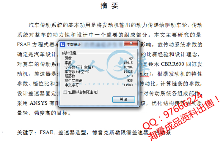
汽车传动系统的基本功用是将发动机输出的动力传递给驱动车轮,传动系统对整车的动力性和设计中一个重要的组成部分。本文主要研究的是FSAE方程式赛车传动系统的燃油经济性有很大的影响,故传动系统参数的确定是汽车设计,基于我院LS Racing车队三年来的比赛经验和设计理念,对赛车的传动系统进行优化和改造。本赛车选用的是铃木CBRR600四缸发动机,差速器是选用德雷克斯勒限滑差速器(Drexler),根据发动机的特性参数、档位比和差速器的工作原理,选择合适的链传动比,计算链条的参数,设计差速器固定支架,合理的布置整个传动系统。针对传动系统各组成部件,采用ANSYS有限元分析软件对零部件进行强度校核,优化结构使其达到质量轻、强度高的目标。

关键字:FSAE,差速器选型,德雷克斯勒限滑差速器,传动系

Formula SAE of china (transmission and final drive system)

ABSTRACT

The basic function of auto transmission system is transfer engine power to drive wheels .The transmission system has a great influence in dynamic performance .So the parameter of drive system is one of the important part in automobile design .The article mainly research is drive system design of FSAE racing car. The car drive system optimization and transformation is based on LS Racing team competition experience and design concept in the past three years .The racing car engine is choose SUZUKI GSX-R600 have four cylinder engine .The differential is choose Drexler limited slip differential. According to the characteristics of the engine parameters, gear ratio and differential working principle ,that choose the right chain transmission ratio, calculation chain parameters, design the differential fixed bracket, reasonable arrangement of the drive system. Aimed at the transmission system components, use the ANSYS finite element analysis to check intensity of the parts, that optimize structure enables it to achieve light weight, high strength goal.

KEY WORD: FSAE, Differential selection, Drexler limited slip differential, the ANSYS finite element analysis


目 录

第一章 大赛背景及发展现状1

§1.1 赛事背景1

§1.2 国外情况2

§1.3 国内情况2

第二章 绪论4

§2.1 传动系统的组成4

§2.2 传动系统的功能实现4

§2.3 FSAE大学生方程式赛车传动系统的特点5

§2.4 中国大学生方程式汽车大赛(FSC)传动规则和要求6

§2.5 本次传动系统设计任务6

第三章 赛车动力总成的选择与布置7

§3.1 整车参数与主要结构7

§3.2 赛车动力性计算9

§3.2.1 主减速比确定9

§3.2.2 赛车驱动力的计算9

§3.3 赛车动力性的验证与优化11

§3.3.1 拟合外特性曲线图11

§3.3.2 驱动力-行驶阻力平衡图12

§3.3.3 发动机功率-行驶阻力功率平衡图12

§3.3.4加速度特性曲线13

§3.3.5 动力因数图14

§3.4 传动方式确定14

第四章 动力总成与车架的连接及与驱动轮的传动设计17

§4.1 差速器固定17

§4.2 车轮法兰设计19

§4.3 大小链轮的设计20

§4.3.1 链轮齿数  、 和传动比i的计算与确定20

§4.3.2齿数的选取原则20

§4.3.3 传动比的确定20

§4.3.4  链轮的计算与选取20

§4.4 差速器的设计与选择25

§4.4.1 差速器原理25

§4.4.2 差速器的分类26

§4.4.3 方程式赛车的差速器结构选择30

§4.4.4 差速器选用说明31

§4.5 万向节的选择31

§4.5.1 万向节的工作原理32

§4.5.2 等速万向节的分类32

§4.6 此次设计选用的万向节类型35

参考文献37

结束语38


第一章 大赛背景及发展现状

随着我国汽车工业的崛起,赛车文化日益蓬勃发展,同时为号召十二五时期党中央提出的科技强国口号,在这样一个背景下,2010年首届中国大学生方程式汽车大赛在上海国际赛车场隆重举办。随后的第二届中国大学生方程式汽车大赛的引擎在此轰鸣在上海国际赛车场,规模比前一届扩大将近一倍,吸引了包括一支海外车队——慕尼黑工业大学在内的一共34支队伍参加。在此,我选择FSAE赛车动力及传动总成布置设计为我毕业设计的题目,希望通过此次设计优化让我校的赛车驰骋在2012年上海赛车场。


内容简介:
ORIGINAL ARTICLEDevelopment of an automated testing systemfor vehicle infotainment systemYingping Huang & Ross McMurran & Mark Amor-Segan & Gunwant Dhadyalla &R. Peter Jones & Peter Bennett & Alexandros Mouzakitis & Jan KielochReceived: 18 December 2009 /Accepted: 12 March 2010 /Published online: 15 April 2010# Springer-Verlag London Limited 2010Abstract A current premium vehicle is implemented witha variety of information, entertainment, and communicationfunctions, which are generally referred as an infotainmentsystem. During vehicle development, testing of the info-tainment system at an overall level is conventionally carriedout manually by an expert who can observe at a customerlevel. This approach has significant limitations with regardto test coverage and effectiveness due to the complexity ofthe system functions and humans capability. Hence, it ishighly demanded by car manufacturers for an automatedinfotainment testing system, which replicates a humanexpert encompassing relevant sensory modalities relatingto control (i.e., touch) and observation (i.e., sight andsound) of the system under test. This paper describes thedesign, development, and evaluation of such a system thatconsists of simulation of vehicle network, vision-basedinspection, automated navigation of features, randomcranking waveform generation, sound detection, and testautomation. The system developed is able to: stimulate avehicle system across a wide variety of initialisationconditions, exercise each function, check for systemresponses, and record failure situations for post-testinganalysis.Keywords Automatic testing.Infotainment.Image processing.Modeling and simulation.Hardware-in-the-loop.Robustness.Validation1 IntroductionAn infotainment system provides a variety of information,entertainment, and communication functions to a vehiclesdriver and passengers. Typical functions are route guidance,audio entertainment such as radio and CD playback, videoentertainment such as TVand interface to mobile phones, aswell as the related interface functions for the users tocontrol the system. There has been a large growth in thisarea driven by rapid developments in consumer electronicsand the customer expectations to have these functions intheir vehicles. Examples of this are surround sound, DVDentertainment systems, iPod connectivity, digital radio andtelevision, and voice activation.With this growth in features there has been acorresponding increase in the technical complexity ofsystems. In a current premium vehicle, the infotainmentsystem is typically implemented as a distributed systemconsistingofanumberofmodulescommunicatingviaahighspeed fiber optic network such as Media Orientated SystemsTransport (MOST). In this implementation the infotainmentsystem is in fact a System of Systems (SOS) with individualsystems having autonomy to achieve their function, butsharing resources such as the HumanMachine Interface(HMI), speakers, and communication channel 1. Typicalissues with such SOS are emergent behavior as systemsinteract in an unanticipated manner particularly duringsome initialisation conditions where it may be possible toget delays and failures in individual systems. These maynot be readily observable until the particular part of theY. Huang (*):R. McMurran:M. Amor-Segan:G. DhadyallaWarwick Manufacturing Group, University of Warwick,Coventry CV4 7AL, UKe-mail: yingping.huangwarwick.ac.ukR. P. JonesSchool of Engineering and IARC, University of Warwick,Coventry, UKP. Bennett:A. Mouzakitis:J. KielochJaguar Land Rover, Engineering Centre,Coventry, UKInt J Adv Manuf Technol (2010) 51:233246DOI 10.1007/s00170-010-2626-2ntssystem is exercised. During vehicle development, valida-tion of the infotainment system is extremely important andis conventionally carried out manually by engineers whocan observe at a customer level but this has limitations withregard to test coverage and effectiveness. The firstlimitation is the time available to do manual tests, whichis constrained by the development time scale and engineersworking hours. The second is in the repeatability of the test,which is subject to human error. Hence, there is arequirement for an automated infotainment test capability,which replicates a human expert encompassing relevantsensory modalities relating to control (i.e., touch and voice)and observation (i.e., sight and sound) of the system undertest. This test capability must be able to stimulate thesystem across a wide variety of initialisation conditionsincluding those seen under cranking, low battery or faultconditions, exercise each function, check for systemresponses, and record related data, e.g., MOST bus trace,in the case of a malfunction for subsequent analysis. Thispaper describes the design and development of such asystem as part of a UK academic and industrial collabora-tive project into the validation of complex systems.In the system, a Hardware-in-the-Loop (HIL) platformsupported by a model-based approach simulates the vehiclenetwork in real time and dynamically provides variousessential signals to the infotainment system under test. Sincethe responses of the system are majorly reflected in thedisplay of the touch screen, a machine vision system isemployed to monitor the screen for inspection of thecorrectness of the patterns, text, and warning lights/tell-tales.The majority of infotainment functions are accessed by theuser through an integrated touch screen. In order to achieve afully automated testing, a novel resistance simulationtechnique is designed to simulate the operation of the touchscreen. It is known that voltage transient processes, such asengine start where an instantaneous current inrush can reach800 A, may result in some failures on the system. To test thesystem robustness against low voltage transient conditions, atransient waveform generator is developed to mimic threespecific transient processes. A testing automation softwareintegrates and controls all devices to form a fully automatedtest process, which can be run continuously over days oreven weeks. The developed testing system not only makesvarious testing possible, repeatable, and robust, but alsogreatly improves testing efficiency and eases the task oftedious validation testing.Model-based testing of functionality of an ElectronicControl Unit (ECU) using HIL has been implemented byautomotive manufacturers over the last few years 25.Currently, Jaguar Land Rover (JLR) has adopted the HILtechnology for automated testing and validation of elec-tronic body systems, powertrain, and chassis controlsystems 6, 7. The benefits of this technology includeautomated testing, earlier testing before physical prototypevehicle build, ability to perform robustness and dynamictesting, and reduction of supplier software iterations.Machine vision systems have been used in many manufac-turing applications such as automotive 810, roboticguidance 11, and tracing soldering defects 12, 13. Theauthor also employed machine vision technology forobstacle detection in advanced driver assistant systems14, 15. However, no research has been reported using amachine vision system for design validation testing.Validation testing in the design stage is very much differentfrom testing in manufacturing. Firstly, design validationtesting requires diverse test cases covering a large numberof, rather than a restricted, set to prove proper design. Theonly way to generate the test cases when the car is in theearly development phases is using model-based testingtechniques, which simulate vehicle-operating conditions inreal time. Secondly, design validation testing requiresiterative and repeated tests for robustness evaluation,although it does not require a high volume of parts to betested. Thirdly, design validation testing needs frequentadaptation of the testing system for different types of carsor for different development stages of the same car. Onenovelty of this paper is the integration of the machinevision and HIL techniques for complex design validationtesting. In addition, the paper proposes a novel pseudo-random concept for generating three voltage transientwaveforms, which allows the testing to mimic the randomprocess as seen in real cases, and also enables the testing tobe regenerated for further investigations. Furthermore, acommon approach to mimic the operation of the touchscreen by a human is by using robot arms. In this design, acrafty resistance simulation approach replaces the robotarms to achieve the goal. The approach can be completelyimplemented in software by using the HIL simulator,therefore eliminating the need of complicated mechanicaldevices such as robot arms, pneumatic/hydraulic, andsolenoid actuators.2 System configurationsThe configuration of the system developed for testing theinfotainment system is shown in Fig. 1. The system consistsof six vital elements including the unit under test, HILtester, machine vision (camera), operation of the touchscreen, transient waveform generator, and test automation.The infotainment system under test consists of a numberof modules including the radio/CD player, amplifier(AMP), navigation system, blue tooth/telephone/USB,vehicle setup, auxiliary audio interface, and climate controlfunctions. The HMI is based primarily on a 7 TFT resistivetouch screen with additional hard keys on an Integrated234 Int J Adv Manuf Technol (2010) 51:233246ntsControl Panel (ICP) in the center console and remotecontrols on the steering wheel. Audio output is via a DSPamplifier. Communication between the modules is througha MOST optical bus carrying control, data, and audioinformation. The infotainment system is connected to therest of the vehicle via a module called ICM acting as agateway between MOST and a vehicle Controller AreaNetwork (CAN) bus. It is worth noting that the ICP and theremote controls on the steering wheel reside in the vehicleCAN bus. In addition, a MOST analyzer was connected inthe MOST ring during the testing. The MOST analyzer wascontrolled by the HIL tester via digital outputs to trigger thelogging of the MOST traces when a failure occurs.Within the testing system, the HIL tester simulates thevehicle network and dynamically provides various essentialsignals to the infotainment system under test. It also acts as acontrol center to control other devices. For example, it sendscommands via a serial port to trigger the camera and receivethe inspection results from the camera. The machine visionsystem (camera) checks the responses of the system bymonitoring the display of the touch screen such as patternsand text. The operation of the touch screen is achieved byusing a resistance simulation approach, which is imple-mented in the HIL tester. By using this approach, the testingsystem can get access to the majority of infotainmentfunctions. The transient waveform generator producesvoltage signals and powers up the infotainment system viaa programmable power supplier. The waveform generator,mimicking three voltage transient processes, is used fortesting system robustness against low voltage events. Thetest automation is running in the host computer to integrateand control all devices to form a fully automated testprocess. In addition, the host PC has been linked with themachine vision system via a TCP/IP Ethernet communica-tion. This link allows the storage of time-stamped images inthe host PC so that the behavior of the unit under test can bereviewed offline in terms of the test results. The followingsections describe the individual elements of the automatedtesting system including the HIL tester, vision-basedinspection, automated touch screen operation, transientwaveform generator, and test experiments.3 HIL testerA dSPACE simulator 16 was used to form a hardware-in-the-loop simulation test system. The HIL test systemsimulates the vehicle CAN bus to provide power modesignals to the MOST Network via the MOST gateway. Italso simulates the ICP to operate the infotainment system.Test ScriptPrecondition.test.post conditionPrecondition.test.post conditionPrecondition.test.post conditionPrecondition.test.post conditionPrecondition.test.post condition.Test ResultsPrecondition. te s t.post condition Precondition. te s t.post condition Precondition. te s t.post condition Precondition. te s t.post condition Precondition. te s t.post condition.OpticalControl ParametersCapture DataHostPCCameraTest ResultsVision TestTriggerTest Automation scriptsImages (referenced to test)RS232 SerialEthernetTrigger Low Voltage test profileRS232Transient waveform generatorHIL TesterMOST RingCANAMPOptolyserAudio output monitoringResistive control of touch screenPowerSupplyClimate/Setup/InterfaceICM gatewayRadio/CDplayerBlue tooth/Phone/USBMOST analyzerMOST AnalyzertriggerTouchScreenNavigationICP & Remote Cont Fig. 1 System configurationInt J Adv Manuf Technol (2010) 51:233246 235ntsIn addition, the HIL tester also provides RS 232 serialinterfaces to communicate with the camera and transientwaveform generator, resistance simulation to operate thetouch screen, and an A/D interface for detecting sound andmeasuring sound frequency.ThedSPACESimulatorconsistsofsimulationmodelsandexpansion hardware as shown in Fig. 2. The expansion boxincludes one processor board DS1006 and one interfaceboard DS2211. The DSP board runs the simulation models,while the interface board provides various interface linkswith other devices, such as CAN, resistance outputs, A/Dconverters, analog/digital input and output, and RS 232serial communication to control the machine vision system.In the HIL system, simulation models are implementedin MATLAB/Simulink/Stateflows and compiled using theauto-C-code generation functions of Matlabs Real-TimeWorkshop for real-time execution.3.1 Simulation of power modeThe behavior of the components of the Infotainment systemis determined by a CAN signal known as Power mode,which indicates the operational state of the vehicle e.g.,ignition off,ignition on,engine cranking,enginerunning, etc. To test the performance of the infotainmentsystem under cranking conditions, the car under test must bein the engine-cranking state when applying crankingtransient voltages to the car. Moreover, any subsequentfunctional tests must be conducted in the engine-runningstate after the cranking. In a real car, power mode messagesare transmitted by the body ECU connected to the CAN.Since we were testing the infotainment system on a testplatform representing a real car sometimes, in order togenerate the correct power mode behavior, we utilized CANsimulation of the HIL tester to simulate the body ECU totransmit power mode messages to the MOST gateway.3.2 ICP simulationThe Integrated Control Panel of the infotainment systemprovides users with a number of hard keys for operating thesystem. The functions controlled by the ICP includeselection of the audio sources, loading and ejecting CDs,seeking up/down for radio stations and CD tracks, volumecontrols, and so on. To enable an automated testing of thesefunctions, the ICP must be controlled by the test center, thedSPACE real-time simulator.The ICP electronic control unit interfaces with a vehiclevia the vehicle CAN. Therefore, the ICP unit was simulatedby using the CAN simulation of the dSPACE simulator.The models of ICP simulation are shown in Fig. 3.3.3 Sound detectionSound detection contains two aspects i.e., detecting soundon or off and detecting the frequency (dominant) of thesound. The sound signal is sampled from the speaker end asshown in Fig. 1, and converted into digital signal by an A/Dconverter within the dSPACE simulator. The sound on/offis determined by checking the amplitude of the signal. Thefrequency of the sound is detected by the specific circuit ofthe simulator. The purpose of detecting sound frequency isto identify a sound source and active CD track. The modelis shown in Fig. 4.Power supply controlSimulation of touch Screen operationand On/Off Switches -resistance outputsSerial communications RS232Digital signal processorStandard I/OInterfaceSimulation ModelsExpansion boxCAN I/O RS232Real-time simulatorSimulation of Power Mode and integrated control panel - CANSound detection and measuring sound frequency A/D inputsFig. 2 dSPACE real-time simulator236 Int J Adv Manuf Technol (2010) 51:233246nts3.4 Simulation of serial communicationsThe RS232 serial communication is used to establishthe link between the HIL tester with the camera and thetransient waveform generator so that closed loop testingcan be performed. During the test, the HIL tester is thecontrol center to command the camera and the transientwaveform generator and to obtain the inspection resultsfrom them. For example, the camera needs to becommanded to select a specific image processing jobfile for specific testing. The checking results generatedbythecameraneedtobereturnedtotheHILtester.The transient waveform generator needs to be com-manded to generate a specific cranking waveform forspecific testing. The parameters of the waveformresulting in a failure need to be returned to the HILtester so that this specific testing can be duplicated inthe later analysis stages.A simplified version of the simulation models of theRS232 serial communication is shown in Fig. 5.Atransmitted message is ended with a carriage return andhas a maximum length of 10 bytes. A received message hasa fixed length of 8 bytes. The first 3 bytes gives the resultname while the following 5 bytes indicates the resultvalues. For example, the active track number is abbreviatedas the result name ATN.Fig. 3 Model of ICP simulationInt J Adv Manuf Technol (2010) 51:233246 237nts4 Vision-based inspection4.1 Machine vision systemThe machine vision system consists of a camera, lighting,optics, and image processing software. A Cognex In-sightcolor vision sensor 17 was selected for image acquisitionand processing, which offers a resolution of 640480 pixelsand a 32-MB flash
温馨提示:
1: 本站所有资源如无特殊说明,都需要本地电脑安装OFFICE2007和PDF阅读器。图纸软件为CAD,CAXA,PROE,UG,SolidWorks等.压缩文件请下载最新的WinRAR软件解压。
2: 本站的文档不包含任何第三方提供的附件图纸等,如果需要附件,请联系上传者。文件的所有权益归上传用户所有。
3.本站RAR压缩包中若带图纸,网页内容里面会有图纸预览,若没有图纸预览就没有图纸。
4. 未经权益所有人同意不得将文件中的内容挪作商业或盈利用途。
5. 人人文库网仅提供信息存储空间,仅对用户上传内容的表现方式做保护处理,对用户上传分享的文档内容本身不做任何修改或编辑,并不能对任何下载内容负责。
6. 下载文件中如有侵权或不适当内容,请与我们联系,我们立即纠正。
7. 本站不保证下载资源的准确性、安全性和完整性, 同时也不承担用户因使用这些下载资源对自己和他人造成任何形式的伤害或损失。
提示  人人文库网所有资源均是用户自行上传分享,仅供网友学习交流,未经上传用户书面授权,请勿作他用。
关于本文
本文标题:大学生方程式赛车传动及最终传动系统设计【优秀含4张CAD图纸+汽车车辆全套毕业设计】
链接地址:https://www.renrendoc.com/p-475306.html

官方联系方式

2:不支持迅雷下载,请使用浏览器下载   
3:不支持QQ浏览器下载,请用其他浏览器   
4:下载后的文档和图纸-无水印   
5:文档经过压缩,下载后原文更清晰   
关于我们 - 网站声明 - 网站地图 - 资源地图 - 友情链接 - 网站客服 - 联系我们

网站客服QQ:2881952447     

copyright@ 2020-2025  renrendoc.com 人人文库版权所有   联系电话:400-852-1180

备案号:蜀ICP备2022000484号-2       经营许可证: 川B2-20220663       公网安备川公网安备: 51019002004831号

本站为文档C2C交易模式,即用户上传的文档直接被用户下载,本站只是中间服务平台,本站所有文档下载所得的收益归上传人(含作者)所有。人人文库网仅提供信息存储空间,仅对用户上传内容的表现方式做保护处理,对上载内容本身不做任何修改或编辑。若文档所含内容侵犯了您的版权或隐私,请立即通知人人文库网,我们立即给予删除!