毕业设计(论文)开题报告.wps

气流雾化喷枪设计【3张CAD图纸和毕业论文】【答辩优秀】

收藏

压缩包内文档预览:
预览图 预览图 预览图 预览图 预览图 预览图 预览图
编号:475567    类型:共享资源    大小:2.38MB    格式:RAR    上传时间:2015-08-30 上传人:好资料QQ****51605 IP属地:江苏
45
积分
关 键 词:
气流 雾化 喷枪 设计 全套 cad 图纸 以及 毕业论文 答辩 优秀 优良
资源描述:

【温馨提示】 购买原稿文件请充值后自助下载。

以下预览截图到的都有源文件,图纸是CAD,文档是WORD,下载后即可获得。


预览截图请勿抄袭,原稿文件完整清晰,无水印,可编辑

有疑问可以咨询QQ:414951605或1304139763

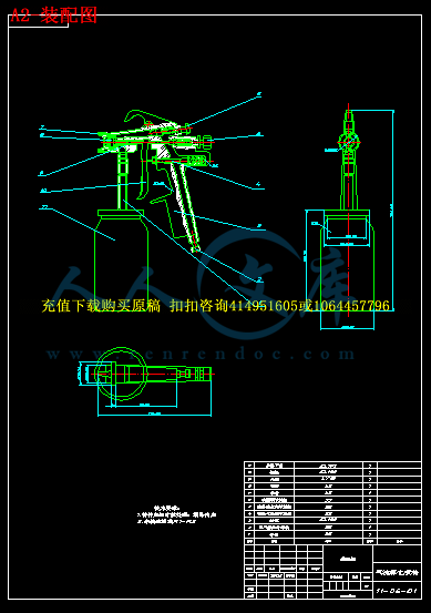
气流雾化喷枪的设计


摘要:高压喷涂是一种利用压缩空气为动力,不直接用压缩空气对涂料进行雾化,它用增压泵将涂料增压至10Mpa-25Mpa,高压涂料通过喷嘴的小喷孔高速喷出雾化分散成极细的雾滴,同时将雾化涂料微粒推至被涂工件表面。

   利用高速气流而令喷枪局部真空,因而产生吸力把油漆从壶中吸到喷咀加以雾化喷出,主要作大面积喷涂,好处是油漆的雾化较佳,可以达到漆膜的厚度及光泽度要求。压力桶为圆柱形压力容器,一般用不锈钢或碳钢制作,桶盖上设置调压阀、压力表及安全阀等附件,调节输入压缩空气的压力可达到输出涂料的压力。压力桶有的还配置气动搅拌器,常用压力桶的容量为10L、20L、40L等。压力桶结构简单,维护方便,涂料输出压力较稳定,不足之处是清洗换色不便。

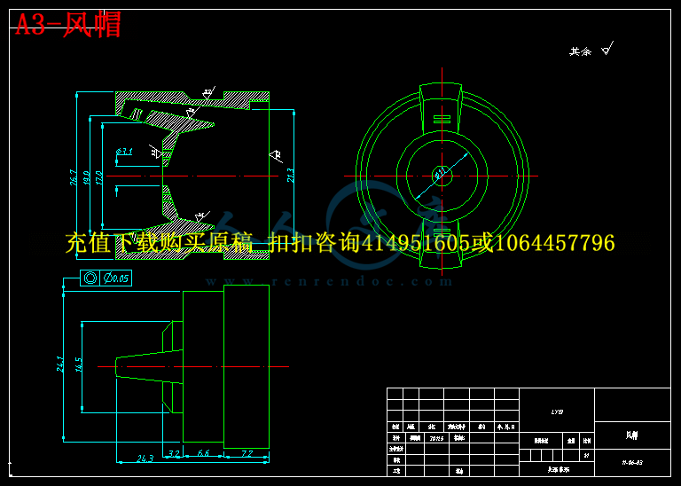
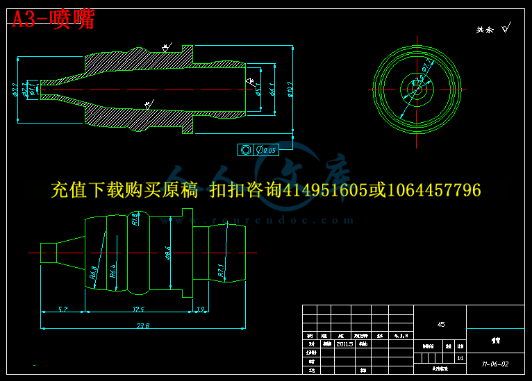
   空气喷枪的空气帽(空气喷嘴)、喷嘴(涂料喷嘴)和顶针,习惯称为空气喷枪的三件套是决定空气喷涂的涂装质量关键部分。气动双隔膜泵,是利用压缩空气作动力,通过换向机构使空气压力作用在横隔膜的内侧,而横隔膜的外侧与泵体共同组成一个容积可以变化的涂料腔。 当左面涂料腔容积从小变大产生局部真空,下面一个单向阀开启,上面一个单向阀关闭,涂料桶中的涂料在大气压力下进入左面涂料腔,而右面涂料腔容积由大变小,下面一个单向阀关闭,涂料产生压力,顶开上面一个单向阀排出泵体。双隔膜泵的两侧有两个涂料腔,当一个容积由小变大,则另一个容积由大变小,周而复始,往返进行。所以双隔膜泵的每次往复都有两次涂料吸入和排出,使泵的输出效率提高,而且输出相对比较平稳。由于压缩空气的输入压力和涂料的输出压力的比率为1:1,故调节压缩空气的输入压力的大小可改变涂料的输出压力。

  高压喷涂可以使用高粘度涂料,大面积喷涂速率达4m2/min-7m2/min,生产效率高。喷涂对涂料无压缩空气混入,漆雾反弹飞散的现象较空气喷涂少,降低了涂料消耗,改善了环境污染。 高压无气喷涂的出漆量较大且漆雾细度不够柔软,涂层厚度不易控制。精装饰涂膜喷涂不及空气喷涂细致。 一般适用于单品种粘度较高的涂料和形状简单、表面积较大的工件批量生产。广泛用于造船、集装箱、钢结构件、建筑内外墙、大型管道等行业。


关键词:压送式喷枪 压缩空气 空气喷枪 气动高压喷涂 气动柱塞泵

       顶针  空气帽


Abstract:   High pressure airless spray gun is a kind of to make use of the compredded air as power, not and directly use the compredded air carries on atomization to the coating, it presses pump to press the coating super - to the 10 Mpas Mpas-25ses with the super -, the high pressure coating passes nozzle of small spray gun hole the high speed spew out the atomization scatter into the most slender fog drop, at the same time atomization coating the corpuscle push into drive Tu Gong Jian's surface.

  Make use of top speed air current but make air gun partial uvauum, as a result generate the vacuum force absorbs to spray Ju to take into atomization jet from the pot the paint and mainly make big area spray gun, the advantage is that the atomization of paint is better, can hit the thickness and water request of painting the film.The press barrel is the cylinder shape press container, generally use stainless clad steel or straight carbon steel creation, the barrel covers setup to adjust to press accesserieses such as valve, pressures gauge and safety valves etc., and the conditioning inputs the press of compredded air to hit the press of outputting the coating.Press barrel have of still install agitator air, the capacity of the wirking pressure barrel is for the 10 Ls, 20 Ls, and 40 L...etc..Press barrel the structure is simple, the maintenance is convenient, the coating outputs press more stable, scarcity of section is cleaning change a color inconvenience.

  Air cap(air noozle), nozzle(coating nozzle) and vertex needle that compresses an air gun, habitually be termed three sets of compressing the air gun is decide air to spray Tu Zhuang mass key fraction.The gas moves a pair of septums pumps, is to make use of compredded air to make power, pass to change to make to get empty a barometric pressure action in the diaphragmatic seamy side toward the mrvhsnidm, while diaphragmatic outside side and pump body constitute a coating chamber that volume can change together.When the left side coating chamber volume became big to generate partial uvauum since the childhood, underneath an one-way valve opened, up an one-way valve locks, the coating in the coating barrel entered a left side coating chamber under the atmospheric pressure, but right surface coating chamber volume from greatly diminished, underneath an one-way valve lock, the coating generated press, the vertex opened over - an one-way valve discharged to pump a body.Two sides of double septum pump contain two coating chambers and be a volume from small become big, then another volume from greatly diminish, go round and begin again, go back and forth progress.So double the septum pump of every time back and forth have two coating suction and discharge and make the output efficiency of pump exaltation, and output contra more steady.Because the ratio of the input press of the compredded air and the output press of the coating is 1:1, the output press of the dimension convertibility coating of the input press of past conditioning compredded air

  High pressure airless spray gun can use higher - viscosity coating, big area spray gun speed reach to the 4 ms 2/ms min-7s 2/min, the production efficiency is high.Spray has no compredded air vs the coating interfusion, paint fog rebound to fly a loose phenomemon compare air spray gun Tu Shao, lowered coating dissipation, improved public nuisances. High pressure airless spray gun's lacquer measures a little bit greatly and paints fog thin degree not enough soft, Tu Ceng's thickness doesn't easily control.The Jing decorates a spray gun of Tu Mo to cannot compare with air spray gun meticulous. Generally compliant unipole species viscosity the higher coating is as simple as shape, the surface accumulate a bigger work piece quantity production.Extensively used for a shipbuilding and gather vanning, the steel structure crafts, such as piece, outside wall inside the building and large piping...etc..

Keywords:  Press a send type air gun  Compredded air  Compress an air gun  The gas moves high pressure airless spray gun  The gas moves plunger pump  Vertex needle  Compress a cap

             Signature of Supervisor:  


目录

1  前言……………………………………………………(8)

2  喷枪简介………………………………………………(9)

 2.1 喷枪的类型……………………………………………………(9)

3  雾化原理………………………………………………(9)

4  气流雾化喷枪的通堵结构方案…………………… (9)

5  喷枪的主要零件………………………………………(12)

 5.1 现将喷头的三个主要件特性介绍 ……………………………(13)

 5.2 喷涂输漆可分为压力桶、气动双隔膜泵……………………(14)

 5.3 喷枪结构技术改造………………………………………………(14)

6  按喷枪工作原理分三类………………………………(24)

 6.1 吸上式、重力式和压送式三种吸上式喷枪………………………(24)

 6.2 喷枪操作及其要点…………………………………………………(25)

7  喷枪的维护与故障处理………………………………(26)

8  气流雾化喷枪的设计与功能………………………(28)

 8.1 特点及应用……………………………………………………(28)

9  供料方式喷枪的雾化技术及其发展趋势……………(29)

结论…………………………………………………………(31)

参考资料……………………………………………………(32)

致谢…………………………………………………………(32)

                    前言


喷枪作为一种生产工具,广泛的应用于社会的各个行业,无论是用于涂装、绘画喷涂、喷漆,还是应用于汽车、钢琴、家电、家具、等表面层的喷漆处理。虽然应用广泛,得到了普遍认可,但同样存在诸多问题如:现象一:喷幅分裂 ,导致其原因:1、涂料黏度太低 2、喷涂压力太高 3、扇面控制孔内径偏大 4、涂料不够 5、雾化空气通道堵塞 。对此采取对策:1、调高涂料黏度 2、调低喷涂压力 3、更换喷嘴套装 4、添加足够的涂料 5、清洁喷枪(spray gun)的空气通道 。又如现象二:跳枪 ,导致其原因:1、喷嘴没拧紧或没装好 2、枪针密封套件松动 3、喷枪(spray gun)的连接螺母松动(下壶喷枪(spray gun)) 4、壶里涂料不足 5、喷嘴套装损坏 ,为此我们采取对策:1、旋紧喷嘴或清洁并安装喷嘴套装 2、紧固顶针密封套件 3、旋紧连接螺母 4、补充涂料 5、更换喷嘴套装 。所以我们致力于一次又一次的发现问题,研究问题,进而改进。我们这次的改进同样也基前人丰硕成果,根据所看到的问题加以研究改装。

在这里对给予本人论文支持和帮助的老师表示衷心的感谢。


1、喷枪简介

喷枪是漆装修理的关键设备。喷枪是将涂料(油漆)均匀地喷涂在车身表面,得到良好的防腐与漆装效果。利用压缩空气对进入喷枪的涂料进行雾化并对车身表面涂敷(简称空气喷射)是车身表面装饰最重要的工艺之一。


1.1 喷枪的类型:

      空气喷枪的类型主要有三种,且每种类型都有其优点及缺点。以下是根据喷枪对油漆的进给方式将喷枪大至分为三类。

内容简介:
ABCs of Spray PaintingABCs of Spray Painting$10.00A-2928-AForwardTable of Contents2While this book examines thespray finishing operation and itsequipment from many viewpoints,there is still much more to belearned to become truly proficientat spray finishing.The best way to becomeproficient at spray finishing is tojust do it! Many trade technicaland community colleges offercourses in spray finishing, a greatway to improve your skills.Many of the “tricks” of theprofessional spray finisher involvepaints and coatings. Themanufacturers of these materialsroutinely publish complete bookson these subjects. Thesepublications are available inspecialty paint stores and willprovide you with considerabledetail. Many of these books alsocontain information on techniquesfor surface preparation.Another important source ofinformation, particularly onequipment use and selection isyour local spray finishingequipment distributor. No bookcould ever completely cover aspecialists in-depth knowledge ofequipment, techniques,maintenance and troubleshooting.Information is available from manyresources on the subject of sprayfinishing. It is our hope that thisbook will provide you with a starttoward perfecting your finishingskills.A recent addition to resourcesavailable to the spray finisher isthe World Wide Web. Manymanufactures are represented andquestion and answer forums areavailable. Please visit our websitesa.t andAbout this book.This book has been updatedseveral times from “The ABCs ofSpray Equipment,” originallypublished by The DeVilbissCompany in 1954. It focuses onequipment and techniques forspray finishing.The format of the original bookwas question-and-answer. Wehave retained that format in thisedition.This book is organized around themajor components of an air spraysystem spray guns, materialcontainers, hose, air controlequipment, compressors, spraybooths, respirators and a shortsection on general cleanliness andother sources of information. Athorough understanding of thematerial in this book - plus a lot ofactual spray painting practice -should enable you to handle justabout any spray painting situation.Although we have made an effortto make this book as detailed andas complete as possible, be awarethat the equipment and productsystems used to illustrate pointsare entirely based on DeVilbisstechnology. DeVilbiss is theworlds oldest and largestmanufacturer of spray paintingequipment, and has maintainedthis leadership since its foundingin 1888.Forward .21. Introduction .3Surface Preparation.3Paint Preparation32. Air Atomizing SprayGuns4Spray Gun Types .4Part Identification andFunction.6Operation .9Maintenance .11Troubleshooting .133. Material Containers.164. Hose and Connections 185. Air Control Equipment.206. Respirators .227. Air Compressors.238. Spray Booths .25.1. Introduction3This book is about the selection,use and maintenance of finishingequipment: spray guns, tanks,cups, hoses, compressors,regulators, spray booths,respirators, etc. It presumes thatyou are familiar with standardsurface preparation techniquesthat may be required beforefinishing actually begins. It alsopresumes a basic knowledge ofthe many different types of paintsand coatings available.Creating a perfect finish requires asolid knowledge of surfacepreparation, finishes and spraypainting equipment. The first twoare extensively covered in manyother books. The manufacturers ofpaints and coatings have gone togreat length to publish informationon their new and existingproducts.But, even an extensive knowledgeof surface preparation techniquesand paint chemistry is not enoughto assure a professional finish.The finish must be applied by aspray gun, and all the variables ofits use must be mastered.The equipment necessary to applythe finish the spray gun, tank,cup, regulator, hoses,compressor, etc. must all bematched to the job as well as toeach other. That equipment mustbe used and maintained properly,with an appreciation of how andwhy it works the way it does.The moment of truth for any finishhappens when the trigger ispulled. This book focuses on thatmoment.Surface PreparationThe surface to be finished shouldbe well cleaned before painting. Ifthe paint manufacturersinstructions call for it, the surfaceshould be chemically treated. Usea blow-off gun and tack rag toremove all dust and dirt. Noamount of primer or paint willcover up a badly preparedsurface.Plastic parts may contain staticelectricity from the moldingprocess. This static attractsparticles of dust and dirt. Eliminatethem by treating with “destatisiz-ing” air using a special blow-offgun that imparts a neutral chargeto the airflow. A chemical anti-static treatment is also available.Paint PreparationTodays finishes are extremelycomplex chemical formulations.They include both solvent andwaterborne types. Some mayrequire the addition of solvents toform the proper spraying viscosity.Others may simply require theaddition of a second component ata prescribed ratio to obtainsprayable consistency. Many ofthem also have hardeners or otherchemicals, added to them toinsure correct color match, gloss,hardness, drying time or othercharacteristics necessary toproduce a first class finish. Makesure you are familiar with thespecific finish material data sheetsaccompanying each material. Donot mix materials from variousmanufacturers. Read and followdirections carefully.All finish materials must also besupplied with a Material SafetyData Sheet (MSDS). This dataprovides information on properhandling and disposal ofmaterials. Many states require thatMSDS be kept on file by the user.The first step is knowing the typeand color of paint the projectrequires. With this determined,follow the manufacturersinstruction for preparing it exactly.If you have any doubts about howto proceed, dont guess! Contactyour paint supplier for help.Improperly prepared paint willnever produce a good finish!The chief characteristic thatdetermines the sprayablility ofpaint and how much film may beapplied is its viscosity orconsistency. Following the paintmanufacturers instructions will getyou close, but for professionalresults, use a viscosity cup. It is asimple but very accurate way tomeasure the thickness of paint.With the cup, you can thin orreduce the paint to the preciseconsistency required by themanufacturer.Always prepare paint in a clean,dust-free environment. Paint has aremarkable ability to pick up dirt.Dirty paint will not only clog yourspray gun, but it will also ruin yourpaint job. Get in the habit ofalways pouring paint into the cupor tank through a paint strainer.Paint is never as clean as it looks.32. Air Atomizing Spray Guns4IntroductionThe spray gun is the keycomponent in a finishing system. Itis a precision engineered andmanufactured instrument. Eachtype and size is specificallydesigned to perform a certain,defined range of tasks.As in most other areas of finishingwork, having the right tool for thejob goes a long way toward get-ting professional results.This chapter will help you knowwhich is the proper gun by review-ing the Conventional Air and HighVolume/Low Pressure spray gundesigns commonly used in finish-ing - suction feed, gravity feed andpressure feed. It will also reviewthe different types of guns andcomponents within each design.A thorough understanding of thedifferences between systems willallow you to select the right gun,to use it properly to produce ahigh quality finish and to con-tribute toward a profitable finishingoperation.SPRAY GUN TYPES1. What is an air spray gun?An air spray gun is a tool whichuses compressed air to atomizepaint, or other sprayable material,and to apply it to a surface.Air and material enter the gunthrough separate passages andare mixed at the air cap in acontrolled pattern.2. What are the types of airspray guns?Air spray guns may be classifiedin various ways. One way is by thelocation of the material container:Figure 1 shows a gun with a cupattached below it.Figure 3 shows a gun with a cupattached above it.Figure 4 shows a material con-tainer some distance away fromits pressure feed gun.The type of material feed systemis also a way of classifying guns:Suction Feed. draws material tothe gun by suction as in Figure 1.Gravity Feed. the material travelsdown, carried by its own weightand gravity as in Figure 3.Pressure Feed. the material isfed by positive pressure as inFigure 4.Guns may also be classified aseither external or internal mixdepending upon the type of aircap.3. What is a suction feed gun?A spray gun design in which astream of compressed air createsa vacuum at the air cap, providinga siphoning action. Atmosphericpressure on the material in thesuction cup forces it up the suctiontube, into the gun and out the fluidtip, where it is atomized by the aircap. The vent holes in the cup lidmust be open. This type gun isusually limited to a one-quart, orsmaller, capacity container andlow to medium viscosity materials.Figure 1- Suction Feed Gun withattached cupSuction feed is easily identified bythe fluid tip extending slightly be-yond the face of the air cap, seefigure 2.Figure 2 - Suction Feed Air CapSuction feed guns are suited tomany color changes and to smallamounts of material, such as inautomotive panel/bumper repairsand completes, touchup, orlower production operations.4. What is a gravity feed gun?This design uses gravity to flowthe material from the cup, which ismounted above the gun, into thegun for spraying. No fluid pickuptube is used, since the fluid outletis at the bottom of the cup.This cup has a vent hole at the topof the cup that must remain open.It is limited to 34 ounce capacitiesdue to weight and balance.Gravity feed guns are ideal forsmall applications such asautomotive panel/bumper repairsand completes, spot repair,orfor finishing in a limited space.They require less air than a suctionfeed gun, and usually have lessoverspray.Figure 3- Gravity Feed Gun withattached cup2. Air Atomizing Spray Guns (Contd)55. What is a pressure feed gun?In this design, the fluid tip is flushwith the face of the air cap (seeFigure 5). The material ispressurized in a separate cup,tank or pump. The pressure forcesthe material through the fluid tipand to the air cap for atomization.Figure 4 - Typical Pressure Feed Gunwith remote potThis system is normally usedwhen large quantities of materialare to be applied, when thematerial is too heavy to besiphoned from a container orwhen fast application is required.Production spraying in amanufacturing plant or fleetrefinishing operation is a typicaluse of a pressure feed systemFigure 5 - Pressure Feed Air CapTypeViscosityFluidAtomizing TypeFeed(#2 Zahn)Oz/MinutePressureProductionSuctionup to 2410-1240-50LowGravityup to 2410-1212-2430-50LowPressure up to 2950-60High6. What is an external mix aircap?This gun mixes and atomizes airand fluid outside the air cap.It can be used for applying alltypes of materials, and it isparticularly desirable whenspraying fast drying paints such asbasecoat and lacquer. It is alsoused when a high quality finish isdesired.Figure 6 - External Mix Gun7. What is an internal mix cap?This cap mixes air and materialinside the air cap, before expellingthem.It is normally used where low airpressures and volumes areavailable, or where slow-dryingmaterials are being sprayed.A typical example is spraying flatwall paint, or outside house paint,with a small compressor.Internal mix caps are rarely usedfor finishing when a fast-dryingmaterial is being sprayed, or whena high quality finish is required.Figure 7 - Internal Mix Air Cap8. What is HVLP?HVLP, or High-Volume/LowPressure, uses a high volume ofair (typically between 15-26 CFM)delivered at low pressure (10 PSIor less at the air cap) to atomizepaint into a soft, low-velocitypattern of particles.In many cases, less than 10 psi isneeded in order to atomize.Proper setup utilizes no more fluidand air pressure than is needed toproduce the required quality and aflow rate that will meet productionrequirements.As a result, far less material is lostin overspray, bounceback andblowback than with conventionalair spray. This is why HVLPdelivers a dramatically highertransfer efficiency (the amount ofpaint that adheres to the substratecompared to the amount of paintsprayed) than spray systemsusing a higher atomizing pressure.The HVLP spray gun resembles astandard spray gun in shape andoperation. Models that use highinlet pressure (35-80 psi) andconvert to low pressure internallywithin the spray gun are calledHVLP conversion guns.Some HVLP models, particularlythose using turbines to generateair, bleed air continuously tominimize back- pressure againstthe air flow of the turbine.The air cap design is similar tothat of a standard spray gun, witha variety of air jets directing theatomizing air into the fluid stream,atomizing it as it leaves the tip.HVLP is growing in popularity andnew environmental regulations arerequiring it for many applications.HVLP can be used with a widevariety of materials, includingtwo-component paints, urethanes,acrylics, epoxies, enamels,lacquers, stains, primers, etc.A DeVilbiss Pro Tip:When using a gravity feed system,downsize the tip one size from suction.If the suction system calls for a .070”,use a .055” or .063”52. Air Atomizing Spray Guns (Contd)6PART IDENTIFICATIONFUNCTION9. What are the principal partsof a spray gun?Figure 8 - Spray Gun Anatomy10. What happens when thetrigger is pulled?The trigger operates in twostages. Initial trigger movementopens the air valve, allowing air toflow through the gun.Further movement of the triggerpulls the fluid needle from its seatat the fluid tip, allowing fluidmaterial to flow. When the triggeris released, the fluid flow stopsbefore the air flow.This lead/lag time in the triggeroperation assures a full spraypattern when the fluid flow starts.It also assures a full pattern untilthe fluid flow stops, so there is nocoarse atomization.11. What is the function of the aircap?The air cap (see figure 10) directscompressed air into the fluidstream to atomize it and form thespray pattern. (see Figure 9)Round Tapered BluntFigure 9 - Types of Spray PatternsThere are various styles of caps toproduce different sizes andshapes of patterns for manyapplications.12. What are the advantages ofthe multiple jet cap?This cap design provides betteratomization of more viscousmaterials.It allows higher atomizationpressures to be used on moreviscous materials with less dangerof split spray pattern.It provides greater uniformity inpattern due to better equalizationof air volume and pressure fromthe cap.It also provides better atomizationfor materials that can be sprayedwith lower pressures.Figure 10 - Multiple Jet External MixAir Cap13. How should an air cap beselected?The following factors must be con-sidered:a) type, viscosity and volume ofmaterial to be sprayedb) size and nature of object, orsurface to be sprayed (multiple, orlarger, orifices increase ability toatomize more material for fasterpainting of large objects).Fewer, or smaller orifices usuallyrequire less air, produce smallerspray patterns and deliver lessmaterial. (These caps aredesigned for painting smallerobjects and/or using slowerspeeds)c) material feed system used(pressure, suction or gravity)d) size of fluid tip to be used(most air caps work best withcertain fluid tip/needlecombinations)e) volume of air in cubic feet perminute (cfm) and pressure inpounds per square inch (psi) avail-able.See the DeVilbiss spray guncatalog for proper selection of aircap / fluid tip / needlecombinations and typical uses.14. What is the function of thefluid tip and needle?They restrict and direct the flow ofmaterial from the gun into the airstream. The fluid tip includes aninternal seat for the tapered fluidneedle, which reduces the flow ofmaterial as it closes. (see Figure11).The amount of material thatleaves the front of the gundepends upon the viscosity of thematerial, the material fluidpressure and the size of the fluidtip opening provided when theneedle is unseated from the tip.Fluid tips are available in a varietyof sizes to properly handlematerials of various types, flowrates and viscosity.Figure 11 - The Fluid Tip andNeedleAirCapFluidTipFluidNeedleNeedlePackingAirValveSpreaderAdjustmentValveFluidAdjustmentScrew2. Air Atomizing Spray Guns (Contd)715. What is the nozzlecombination?In practice, the air cap, fluid tip,needle and baffle are selected asa unit, since they all work togetherto produce the quality of the spraypattern and finish. These fouritems, as a unit, are referred to asthe nozzle combination.16. What are standard fluid tipsizes and flow rates?The standard sizes, correspondingfluid tip opening dimensions andflow rates are:Rule of thumbOptimum fluid pressureis 8-20 psi.Pressures greater than thisgenerally indicate the need for alarger fluid tip size.17. How are fluid tip and needlesizes identified?DeVilbiss fluid tips and needlesare identified by the lettersstamped on the tip and theneedle.The identification letters on thesecomponents should match. Seethe appropriate DeVilbiss spraygun catalog for the properselection of fluid tip and needlecombinations.18. What fluid tip and needlecombination sizes are mostcommon?1.0, 1.1, 1.4 and 1.8 are mostgenerally used. The 1.4 and 1.6combination is used for gravityfeed, while 1.6 and 1.8 are usedfor suction feed. For pressure feedthe most common tips are 1.1mmand 1.4mm.19. How are nozzlecombinations selected?Five basic considerations are in-volved in selecting the nozzlecombination:type and viscosity of materialbeing sprayedphysical size of object beingfinished/fan pattern sizedesired speed/finish qualitygun model being usedavailable air volume (cfm) andpressure (psi) fromcompressor(1) The type and viscosity of thematerial being sprayed is thefirst factor to consider.Rule of thumbThe lower the viscosity of thematerial, the smaller the I.D. of thefluid tip.MaterialProductionTipViscosityRateSize#2 Zahnup to 23 secLow1.1 mm1.4 mm1.8 mm2.2 mm23-28 secMed28-48 secHighover 48 secHighNOTE: Viscosity conversioncharts are available to convert oneviscosity cup reading to anotherfrom any material or equipmentsupplier.(2) The physical size of the objectto be painted must also beconsidered. As a general rule, usethe largest possible spray patternconsistent with the object size.Remember that different air capsdeliver various patterncharacteristics. This can reduceboth spraying time and thenumber of gun passes.(3) The next consideration inevaluating nozzle combinations isthe speed with which the finish willbe applied and the desired level ofquality.For speed and coverage, choosea nozzle combination whichproduces a pattern as wide aspossible.When quality is the decidingfactor, choose a nozzlecombination which produces fineatomization and a smaller patternsize, thereby giving greaterapplication control.(4) The model of the gun itself willlimit the selection of nozzlecombination.For a DeVilbiss suction feed gun,there are several nozzle typesavailable which are suitable forfinishing operations. ThesePlus Technology(High Efficiency) Tip Size Max. Flow RateGravity Feed1.2 mm/.0476 oz./min.1.3 mm/.0517 oz./min.1.4 mm/.0558 oz./min.1.5 mm/.0599 oz./min.1.6 mm/.062 10 oz./min.1.8 mm/.070 heavy-bodied materialSuction Feed1.6 mm/.0629 oz./min.1.8 mm/.070 12 oz./min.Pressure Feed1.0 mm/.03910 oz./min.1.4 mm/.05516 oz./min.or heavy-bodied materialHVLP Technology Tip Size Max. Flow RateGravity Feed1.2 mm/.0474 oz./min.1.3 mm/.0515 oz./min.1.4 mm/.0556 oz./min.1.5 mm/.0597 oz./min.1.6 mm/.0628 oz./min.1.8 mm/.070 heavy-bodied materialSuction Feed1.8 mm/.0706 oz./min.2.0 mm/.0787 oz./min.2.2 mm/.0868 oz./min.Pressure Feed1.1 mm/.04212 oz./min.1.4 mm/.05516 oz./min.or heavy-bodied materialConventional Air Spray Tip Size Max. Flow RateGravity Feed1.2 mm/.0476 oz./min.1.3 mm/.0517 oz./min.1.4 mm/.0558 oz./min.1.5 mm/.0599 oz./min.1.6 mm/.062 10 oz./min.1.8 mm/.070 heavy-bodied materialSuction Feed1.6 mm/.0629 oz./min.1.8 mm/.070 12 oz./min.Pressure Feed1.1 mm/.04212 oz./min.1.4 mm/.05516 oz./min.or heavy-bodied material72. Air Atomizing Spray Guns (Contd)8nozzles have fluid tip openingsranging from .062” to.086, andare designed to handle viscositiesup to 28 seconds in a No. 2 ZahnViscosity Cup.For a DeVilbiss pressure feedgun, the amount of materialdischarged depends upon materialviscosity, inside diameter of thefluid tip, length and size of hose,and pressure on the materialcontainer or pump.If the fluid tip opening is too small,the paint stream velocity will betoo high. If the fluid tip opening istoo large, you will lose control overthe material discharging from thegun.For most HVLP guns, the paintflow shouldnt exceed 16 oz. perminute. For higher flow rates,consult the DeVilbiss HVLP SprayGun catalog. (5) Available air supply is the lastfactor to consider.Pressure feed air caps consumebetween 7.0 and 25.0 CFM,depending on design. If your airsupply is limited, because of anundersize compressor, or manyother air tools are in use at once,the gun will be starved for air,producing incomplete atomizationand a poor finish.20. What are the criteria forselecting a pressure feednozzle?While the fluid discharge inounces per minute from a suctionfeed gun is relatively stable(largely because it is determinedby atmospheric pressure), the fluiddischarge from a pressure feedgun depends more upon the sizeof the inside diameter of the fluidtip and the pressure on the paintcontainer or pump. The larger theopening, the more fluid isdischarged at a given pressure.If the fluid tip ID is too small for theamount of material flowing fromthe gun, the discharge velocity willbe too high. The air, coming fromthe air cap, will not be able toatomize it properly causing acenter-heavy pattern.If the fluid tip opening is too large,material discharge control will belost.The fluid tip/air cap combinationmust be matched to each otherand to the job at hand. Spray guncatalogs include charts to help youmatch them properly.21. Of what metals are fluid tipsmade?Tips are made of the followingmetals:a) 300-400 grade stainless steelfor both non-corrosive andcorrosive materialsb) Carboloy inserts for extremelyabrasive materials22. What is viscosity?The viscosity of a liquid is its body,or thickness, and it is a measureof its internal resistance to flow.Viscosity varies with the type andtemperature of the liquid. Anyreference to a specific viscositymeasurement must beaccompanied by a correspondingtemperature specification.The most common measurementused to determine viscosity infinishing is flow rate (measured inseconds from a Zahn, Ford, Fisheror other viscosity cup).Different viscosity cup sizes areavailable. Each cup has a hole atthe bottom, specified to an exactsize. Use a viscosity cup that isdesigned to handle the time rangeof the materials in use. Viscositycontrol is an extremely importantand effective method to maintainapplication efficiency and qualityconsistency. Always measureviscosity after each batch ofmaterial is mixed and make surematerial temperature is the same,normally 70 to 80 F.Viscosity recommendations maybe given in poise and centipoise(1 poise=100 centipoise).Viscosity conversion may beaccomplished by consulting aviscosity conversion chart.23. What is the spreader adjust-ment valve?A valve for controlling the air tothe horn holes which regulate thespray pattern from maximum widthdown to a narrow or round pattern(see figure 8).24. What is the fluid needleadjustment?This adjustment controls thedistance the fluid needle isallowed to retract from its seat inthe fluid tip, which allows more orless material through the fluid tip(see figure 14).With pressure feed systems, thefluid delivery rate should beadjusted by varying the fluidpressure at the pressure pot. Usethe fluid adjustment knob for minorand/or temporary flow control.This will extend the life of the fluidneedle and tip.25. What are the components ofsuction and gravity feedsystems?Typical suction and gravity feedsystems consist of: a suction feedor gravity feed spray gun with cup,an air compressor (not shown), acombination filter/air regulator andair hoses (see figure 12).2. Air Atomizing Spray Guns (Contd)9Figure 12 - Suction Feed andGravity Feed System ComponentsOPERATION26. How is suction and gravityfeed equipment hooked up foroperation?Connect the air supply from thecompressor outlet to the filter/airregulator inlet.Connect the air supply hose fromthe air regulator outlet to the airinlet on the spray gun.After the material has been re-duced to proper consistency, thor-oughly mixed and strained into thecup, attach the gun to the cup(suction feed) or pour material intoattached cup (gravity feed).27. How are suction and gravityfeed systems initially adjustedfor spraying?(1) Spray a horizontal test pattern(air cap horns in a verticalposition). Hold the trigger openuntil the paint begins to run. Thereshould be relatively evendistribution of the paint across thefull width of the pattern. (seeFigure 13). Adjust the patternwidth with the spreaderadjustment valve. If distribution isnot even, there is a problem witheither the air cap or the fluid tipthat must be corrected. Refer tothe Troubleshooting Section forexamples of faulty patterns to helpdiagnose your problem.Figure 13 - Horizontal Test Pattern(2) If the pattern produced by theabove test appears normal, rotatethe air cap back to a normalspraying position and begin spray-ing. (Example - a normal patternwith a conventional or #2000 HVLPair cap will be about 10-11 longwhen the gun is held 8 from the surface).Figure 14 Fluid AdjustmentScrew(3) With the fluid adjusting screwopen to the first thread,(see figure14) and the air pressure set atapproximately 30 psi, or for HVLP10 psi at the air cap. Make a testpass (move the spray gun 3 timesthe normal speed) with the gun onsome clean paper, cardboard orwood. If there are varations inparticle size- specks and/or largeglobs - the paint is not atomizingproperly (see figure 15).(4) If the paint is not atomizingproperly, increase the air pressureslightly and make another testpass. Continue this sequence untilthe paint particle size is relativelyuniform.Uneven distributionEven DistributionFigure 15- Test Patterns(5) If the pattern seems starved formaterial, and the fluid adjustmentscrew allows full needle travel, thefluid tip may be too small or thematerial may be too heavy.Recheck the viscosity or increasethe size of the fluid tip and needle(6) If the material is spraying tooheavily and sagging, reduce thematerial flow by turning in the fluidadjusting screw (clockwise).Remember, proper setup utilizesno more fluid and air pressurethan is needed to produce therequired quality and a flow ratethat will meet productionrequirements.92. Air Atomizing Spray Guns (Contd)1028. What are the components ofa pressure feed system?A pressure feed system consistsof: a pressure feed spray gun, apressure feed tank, cup or pump,an air filter/regulator, appropriateair and fluid hoses, and an aircompressor (see figure 16).Figure 16 - Pressure Feed SystemComponents29. How is equipment hookedup for pressure feed spraying?Connect the air hose from the airregulator to the air inlet on thegun.Connect the mainline air hose tothe air inlet on the tank.CAUTION: Do not exceed thecontainers maximum workingpressure.Connect the fluid hose from thefluid outlet on the tank to the fluidinlet on the gun.30. How is the pressure feedgun adjusted for spraying?Open spreader adjustment valvefor maximum pattern size(seefigure 8).Open fluid adjustment screw untilthe first thread is visible (seefigure 14).31. How is the pressure feedgun balanced for spraying?1) Using control knob on fluidregulator, set fluid pressure at 5 to10 psi.2) Using control knob on air regulator,set air atomization pressure at 25-50psi or for HVLP 10 psi at the air cap. 3) Spray a test pattern (fast pass)on a piece of paper, cardboard, orwood. From that test pattern,determine if the particle size issmall enough and relativelyuniform throughout the pattern toachieve the required finish quality(see figure 15). If particle size istoo large or is giving too muchtexture in the finish, turn theatomization pressure up in 3 to 5psi increments until particle sizeand texture of finish is acceptable.4) Spray a part with thesesettings. If you are not able tokeep up with the production raterequired or if the finish is starvedfor material, increase the fluidpressure with the fluid regulatorcontrol knob in 2 to 4 psiincrements until required wetcoverage is accomplished. Note:A larger capacity fluid tip may berequired.5) Remember, as you turn up thefluid pressure the particle size willincrease. Once the coveragerequired is obtained, it will benecessary to re-adjust theatomization pressure in 3 to 5 psiincrements as explained in step 3to insure required particle size andfinish texture is achieved.6) If using HVLP, using an “AirCap Test Kit” verify that the aircap pressure is not above 10 psi, ifr(see figure 17).equired by a regulatory agencyFigure 17 Air Cap Test KitAfter establishing the operatingpressures required for productionand finish quality, develop aPressure Standardization programfor your finish room to follow.32. What is a PressureStandardization Program?After establishing air and fluidpressures that meet required qual-ity and production, record the datato be used for that application forfuture reference. (see figure 18)Booth #: _Material Sprayed _Application _Viscosity _Fluid Temperature _Spray Gun _Air Cap _ Fluid Tip _Air Pressure _Fluid Pressure _Figure 18 Pressure StandardizationChart33. How should the spray gunbe held?It should be held so the pattern isperpendicular to the surface at alltimes.Keep the gun tip 8-10 inches (airspray guns) or 6-8 inches (HVLPguns) from the surface beingsprayed.2. Air Atomizing Spray Guns (Contd)1134. What is the propertechnique for spray gun strokeand triggering?The stroke is made with a freearm motion, keeping the gun at aright angle to the surface at allpoints of the stroke.Triggering should begin justbefore the edge of the surface tobe sprayed. The trigger should beheld fully depressed, and the gunmoved in one continuous motion,until the other edge of the object isreached. The trigger is thenreleased, shutting off the fluidflow, but the motion is continuedfor a few inches until it is reversedfor the return stroke.When the edge of the sprayedobject is reached on the returnstroke, the trigger is again fullydepressed and the motioncontinued across the object.Lap each stroke 50% over thepreceding one. Less than 50%overlap will result in streaks on thefinished surface. Move the gun ata constant speed while the triggeris pulled, since the material flowsat a constant rate.Another technique of triggering isreferred to as feathering.Feathering allows the operator tolimit fluid flow by applying onlypartial trigger travel.35. What happens when the gunis arced?Arcing the stroke results in unevenapplication and excessive over-spray at each end of the stroke.When the tip is arced at an angleof 45 degrees from the surface(see figure 19), approximately65% of the sprayed material islost.Figure 19 - Spray Techniques36. What is the proper sprayingsequence and technique forfinishing applications?Difficult areas, such as cornersand edges, should be sprayedfirst. Aim directly at the area sothat half of the spray covers eachside of the edge or corner.Hold the gun an inch or two closerthan normal, or screw thespreader adjustment control in afew turns. Needle travel should beonly partial by utilizing the feath-ering technique. Either techniquewill reduce the pattern size.If the gun is just held closer, thestroke will have to be faster tocompensate for a normal amountof material being applied tosmaller areas.When spraying a curved surface,keep the gun at a right angle tothat surface at all times. Followthe curve. While not always physi-cally possible, this is the idealtechnique to produce a better,more uniform, finish.After the edges, flanges and cor-ners have been sprayed, the flat,or nearly flat, surfaces should besprayed.Remember to overlap the previ-ously sprayed areas by 50% toavoid streaking.When painting very narrow sur-faces, you can switch to a smallergun, or cap with a smaller spraypattern, to avoid readjusting thefull size gun. The smaller guns areusually easier to handle in restrict-ed areas.A full size gun could be used,however, by reducing the air pres-sure and fluid delivery and trigger-ing properly.MAINTENANCE37. How should the air cap becleaned?Remove the air cap from the gunand immerse it in clean solvent. Ifnecessary, use a bristle brush toclean dried paint. Blow it dry withcompressed air.If the small holes becomeclogged, soak the cap in cleansolvent. If reaming the holes isnecessary, use a toothpick, abroom straw, or the speciallydesigned cleaning needle andhandle from a Professional SprayGun Cleaning Kit.Cleaning holes with a wire, a nailor a similiar hard object couldpermanently damage the cap byenlarging the jets, resulting in adefective spray pattern.Figure 20 - Cleaning the Air Cap112. Air Atomizing Spray Guns (Contd)1238. How should guns becleaned?A suction or pressure feed gunwith attached cup should becleaned as follows:Turn off the air to the gun, loosenthe cup cover and remove the fluidtube from the paint. Holding thetube over the cup, pull the triggerto allow the paint to drain backinto the cup.Empty the cup and wash it withclean solvent and a clean cloth.Fill it halfway with clean solventand spray it through the gun toflush out the fluid passages bydirecting stream into an approved,closed container. All containersused to transfer flammablematerials should be grounded. (Besure to comply with local codesregarding solvent disposal).Then, remove the air cap, clean itaoutside of fluid tip and baffle area,and replace air cap on the gun.Wipe off the gun with a solventsoaked rag, or if necessary, brushthe air cap and gun with a fiber brushusing clean-up liquid or thinner.s previously explained. Clean To clean a pressure feed gun withremote cup or tank, turn off airsupply to cup or tank. Releasematerial pressure from the systemby opening relief valve.Material in hoses may be blownback. The lid must be loose andfluid pressure off. Keep gun higherthan container, loosen air cap andtrigger gun until atomizing airforces all material back into thepressure vessel.A gun cleaner may be used foreither type of gun. This is an en-closed box-like structure (vented)with an array of cleaning nozzlesinside.Guns and cups are placed overthe nozzles, the lid is closed, thevalve is energized, and thepneumatically controlled solventsprays through the nozzles toclean the equipment.The solvent is contained, andmust be disposed of properly.Some states codes require theuse of a gun cleaner, and it is un-lawful to discharge solvent into theatmosphere.After cleaning a spray gun in agun cleaner, be sure to lubricateas indicated in Figure 22.Figure 21 - Using a Hose CleanerUse a hose cleaner to cleaninternal passages of spray gunsand fluid hose. This deviceincorporates a highly efficient fluidheader, which meters a precisesolvent/air mixture. The cleaneroperates with compressed air andsends a finely - atomized blast ofsolvent through the fluid passagesof the hose, the spray gun, etc.This simple, easy to use cleanerspeeds up equipment cleaningand saves solvent. Savings maybe as much as 80%. It alsoreduces VOC emissions. (Be surethat both the hose cleaner andgun are properly grounded.)Where local codes prohibit the useof a hose cleaner, manuallybackflush the hose into the cup ortank with solvent until clean anddry with compressed air.Clean the container and add cleansolvent. Atomization air should beturned off during this procedure.Pressurize the system and run thesolvent through until clean. (Besure to comply with local codesregarding solvent dispersion anddisposal.)Clean the air cap, fluid tip andtank. Reassemble for future use.39. What parts of the gunrequire lubrication? (Figure 22)The fluid needle packing A, the airvalve packing B and the triggerbearing screw C require dailylubrication with a non-silicone/non-petroleum gun lube.The fluid needle spring D shouldbe coated lightly with petroleumjelly or a non-silicone grease (ie.Lithium).Lubricate each of these pointsafter every cleaning in a gunwasher!Figure 22 - Lubrication PointsCDBA2. Air Atomizing Spray Guns (Contd)13ProblemFluid leaking from packing nutAir leaking from front of gunFluid leaking or dripping fromfront of pressure feed gunJerky, fluttering sprayCause1. Packing nut loose2. Packing worn or dry1. Sticking air valve stem2. Foreign matter on air valve orseat3. Worn or damaged air valve orseat4. Broken air valve spring5. Bent valve stem6. Air valve gasket damaged ormissing1. Dry packing2. Packing nut too tight3. Fluid tip or needle worn ordamaged4. Foreign matter in tip5. Fluid needle spring broken6. Wrong size needle or tipAll Feed Systems1. Loose or damaged fluidtip/seat2. Dry packing or loose fluidneedle packing nut3. Material level too low4. Container tipped too far5. Obstruction in fluid passage6. Loose or broken fluid tube orfluid inlet nippleSuction Feed Only7. Material too heavy8. Air vent clogged9. Loose, damaged or dirty lid10. Fluid tube resting on cupbottom11. Damaged gasket behind fluidtipCorrection1. Tighten, do not bind needle2. Replace or lubricate1. Lubricate2. Clean3. Replace4. Replace5. Replace6. Replace1. Lubricate2. Adjust3. Replace tip and needle withlapped set4. Clean5. Replace6. Replace1. Tighten or replace2. Lubricate packing or tightenpacking nut3. Refill4. Hold more upright5. Backflush with solvent6. Tighten or replace7. Thin or reduce8. Clear vent passage9. Tighten, replace or cleancoupling nut10. Tighten or shorten11. Replace gasket132. Air Atomizing Spray Guns (Contd)14ProblemTop or bottom-heavy spraypattern*Right or left-heavy spraypattern*Center-heavy spray patternSplit spray patternCause1. Horn holes plugged2. Obstruction on top or bottomof fluid tip3. Cap and/or tip seat dirty1. Horn holes plugged2. Dirt on left or right side of fluidtip*Remedies for the top, bottom,right, left heavy patterns are:1. Determine if the obstruction is onthe air cap or fluid tip. Do this bymaking a solid test spray pattern.Then, rotate the cap one-half turn andspray another pattern. If the defect isinverted, obstruction is on the air cap.Clean the air cap as previouslyinstructed.2. If the defect is not inverted, it is onthe fluid tip. Check for a fine burr onthe edge of the fluid tip. Remove with#600 wet or dry sand paper.3. Check for dried paint just insidethe opening. Remove paint bywashing with solvent.1. Fluid pressure too high foratomization air (pressure feed)2. Material flow exceeds aircaps capacity3. Spreader adjustment valve settoo low4. Atomizing pressure too low5. Material too thick1. Fluid adjusting knob turned intoo far2. Atomization air pressure toohigh3. Fluid pressure too low(pressure feed)4. Fluid tip too smallCorrection1. Cstraw or the specially designed cleaning needle and handle from aProfessional Spray Gun Cleaning Kitlean, ream with a toothpick, broom Cstraw or the specially designed cleaning needle and handle from aProfessional Spray Gun Cleaning Kitlean, ream with a toothpick, broom 2. Clean3. Clean1. 2. Clean1. Balance air and fluid pressureIncrease spray pattern width2. Thin or reduce fluid flow3. Adjust4. Increase pressure5. Thin to proper consistency1. Back out counter-clockwise toincrease flow2. Reduce at regulator3. Increase fluid pressure4. Change to larger tip2. Air Atomizing Spray Guns (Contd)15ProblemStarved spray patternUnable to form round spraypatternDry sprayExcessive oversprayExcessive fogWill not sprayCause1. Inadequate material flow2. Low atomization air pressure(suction feed)1. Fan adjustment stem notseating properly1. Air pressure too high2. Material not properly reduced3. Gun too far from surface4. Gun motion too fast1. Too much atomization airpressure2. Gun too far from surface3. Improper technique (arcing,gun speed too fast)1. Too much, or too fast-dryingsolvent2. Too much atomization airpressure1. Pressure feed cap/tip usedwith suction feed2. No pressure at gun3. Fluid needle not retracting4. Fluid too heavy (suction feed)Correction1. Back fluid adjusting screw outto first thread or increase fluidpressure2. Increase air pressure andrebalance gun1. Clean or replace1. Lower air pressure2. Reduce to proper consistencyand temperature solventselect correct3. Adjust to proper distance4. Slow down1. Reduce pressure2. Use proper gun distance3. Use moderate pace, keepinggun parallel to work surface1. Remix with correcttemperature solvent2. Reduce pressure1. Use suction feed cap/tip2. Check air lines3. Open fluid adjusting screw4. Lower fluid viscosity orchange to pressure feed153. Material Containers16IntroductionAll spray painting systems - fromthe smallest brush to the mostsophisticated finishing system-must have containers to hold thematerial being applied.Material container types and sizesvary considerably, depending onthe kind of spraying system beingused.This chapter will discuss thesecontainers, their particular applica-tions, their construction and main-tenance.1. What are materialcontainers?Any container which serves as amaterial supply reservoir for thespray gun. These containers areusually made of metal or plasticwith capacities of 1/2 pint or more.2. What are the types of materialcontainers?There are three common types ofcups which attach to the gun itself:Siphon, Gravity and Pressure.There are also remote pressurecups and tanks, which are locatedaway from the gun. See Page 4for types of guns and systems.3. Where are cup containersused?Cup containers are typically onequart or less, and are used whererelatively small quantities ofmaterial are being sprayed.4. How are material feed cupsattached to lid assemblies?Cups are attached using a lidassembly (sometimes called a cupattachment) that either clamps Aor screws B onto the cupcontainer. (see Figure 1) Some lidassemblies are detachable fromthe gun, while others are integralparts and do not detach from lessexpensive models. A BFigure 1 - Cup Attachment Styles5. What capacity does apressure feed cup have?A pressure feed cup can have aone or two quart capacity.Anything larger is considered apressure feed tank, which may bepositioned some distance from thegun.Figure 2 - Regulated 2 Qt.Pressure Cup6. How do pressure feed tankswork?Pressure feed tanks are closedcontainers, ranging in size fromabout two gallons to 60 gallons.They provide a constant flow ofmaterial, under constant pressure,to the spray gun.The tank is pressurized with clean,regulated, compressed air, whichforces the fluid out of the tankthrough the fluid hose to the gun.The rate of fluid flow is controlledby increasing or decreasing the airpressure in the tank.A typical pressure feed tankconsists of: the shell A, clamp-onlid B, fluid tube C, fluid outlet D,regulator E, gauge F, safety reliefvalve G, and optional agitator H (see figure 3).Pressure feed tanks are availablewith a top fluid outlet and variousaccessories.Figure 3 - Pressure Feed Tank7. Where are pressure feedtanks recommended?Pressure feed tanks provide apractical, economical method offeeding material to the gun overextended periods of time.They are mostly used incontinuous production situations,because the material flow ispositive, uniform and constant.Tanks can be equipped withagitators (see Figure 3) that keep163. Material Containers (Contd)17the material mixed and insuspension.8. When is an agitator used in apressure feed tank?When the material being used hasfiller or pigment that must be keptin motion to keep its particles inproper suspension. An agitatorcan be hand, air or electricallydriven.9. What is a single regulatedtank?This is a pressure feed tank withone air regulator controlling onlythe pressure on the material in thetank (see figure 4).Figure 4 - Single Regulated Tank10. What is a double regulatedtank?This is a pressure feed tankequipped with two air regulators(see figure 5).One provides regulation for the airpressure on the material in thetank (thereby controlling fluidflow). The other controlsatomization air pressure to thespray gun.Figure 5 - Double Regulated Tank11. What are code and non-codepressure tanks?Code tanks are manufactured torigid standards as specified by theAmerican Society of MechanicalEngineers. (ASME) Each step ofmanufacture is closely controlled,and welding of the shell iscertified. Code tanks are designedto withstand pressures up to 110psi.Non-code tanks are normallyrestricted to 3 gallons in size orless. Due to the type ofconstruction, non-code tanks arerated at 80 psi or less.12. What materials are used toconstruct pressure feed tanks?The smaller, non-code, light-dutytanks are made of plated steel andhave lower inlet pressurerestrictions.The heavy-duty, ASME-codetanks are made of galvanized or300 series stainless steel. Theyalso have plated or stainless steellids with forged steel clamps.When abrasive or corrosivematerials are being sprayed, thetank shell is coated or lined with astank liner is used.pecial material, or a polyethylene13. What are tank liners?They are inserts that are placedinside the tank to hold thematerial, keeping it from directcontact with the tank walls. Theyare made of disposablepolyethylene.Using liners reduces tank cleaningtime and makes color changeover and cleanup easier.Note:The A.S.M.E. code, as it relates to pressure vessels attached to spray gun nozzles, is primarily concerned with the use of flammable materials and also covers applications where a tank is used in an OSHA-regulated environment. To comply with OSHA regulations, if you are using a flammable material at greater than 15 PSI and your local fire department has adopted NFPA 33, you must use an A.S.M.E. code tank. Refer to NFPA 33, standard for spray application using flammable or combustible materials.174. Hoses & Connections18IntroductionThe various types of hose used tocarry compressed air and fluidmaterial to the spray gun areimportant parts of the system.Improperly selected or maintainedhose can create a number ofproblems. This chapter will reviewthe different kinds of hose andfittings in use, provide guidance inselecting the proper types for thejob and cover the maintenance ofhose.1. What types of hose are usedin spray painting?There are two types: air hose -used to transfer compressed airfrom the air source to the gun, andfluid hose - used only in pressurefeed systems to transfer thematerial from its container to thespray gun.(NOTE: Do not use air hose forsolvent-based materials.)Figure 1 - Basic HoseConstruction2. How is hose constructed?DeVilbiss hose is a performancedesigned combination of threecomponents: Tube A,Reinforcement B and Cover C.The tube is the interior flexibleartery that carries air or fluidmaterial from one end of the hoseto the other.The reinforcement adds strengthto the hose. It is located betweenthe tube and cover, and it can bemany combinations of materialsand reinforcement design. Itsdesign determines pressurerating, flexibility, kink and stretchresistance and coupling retention.The cover is the outer skin of thehose. It protects the reinforcementfrom contact with oils, moisture,solvents and abrasive objects.The cover protects thereinforcement, but does notcontribute to hose performance.DeVilbiss hose is color-coded:RED or TANair and waterGREYair w/static groundBLACK low pressure fluid3. What type of tube is used influid hose?Since the solvents in coatingswould readily attack and destroyordinary rubber compounds, fluidhose is lined with specialsolvent-resistant nylon materialthat is impervious to commonsolvents.4. What sizes of fluid hose arerecommended?TypeLengthSizeGeneral0 - 251/4 IDPurpose25 - 503/8 ID50 - 1001/2 IDFigure 2 - Recommended fluidhose sizes5. What sizes of air hose arerecommended?The hose from the regulator to agun or tank should be a minimumof 5/16 ID. Tools requiring moreair may need 3/8 I.D. hose orlarger.TypeLengthSize0 - 101/4 IDGeneral10 - 255/16 IDPurpose25 - 503/8 ID50 - 1001/2 ID0 to 255/16 IDHVLP25 - 503/8 ID50 - 1001/2 IDFigure 3 - Recommended airhose sizes6. What is pressure drop?This is the loss of air pressure dueto friction (caused by air flow)between the source of the air andthe point of use. As the air travelsthrough the hose or pipe, it rubsagainst the walls. It loses energy,pressure and volume as it goes.7. How can this pressure dropbe determined?At low pressure, with short lengthsof hose, pressure drop is notparticularly significant. Aspressure increases, and hose islengthened, the pressure rapidlydrops and must be adjusted.All air hose is subject to pressureloss or drop. For example, 1/4pressure drop is 1 psi per foot and5/16 is 1/2 psi per foot. Thispressure loss may result in pooratomization.Too often, a tool is blamed formalfunctioning, when the realcause is an inadequate supply ofcompressed air due to anundersized I.D. hose.184. Hoses & Connections (Contd)19For optimum spray gun results,the following is recommended: upto 25 ft - 5/16 I.D., over 25 ft -3/8 I.D.8. How are hoses maintained?Hoses will last a long time if theyare properly maintained.Be careful when dragging hoseacross the floor. It should never bepulled around sharp objects, runover by vehicles, kinked orotherwise abused. Hose thatruptures in the middle of a job canruin or delay the work.Proper hose cleaning techniquesare covered on Pages 11 and 12.The outside of both air and fluidhose should be occasionallywiped down with solvent. At theend of every job, they should bestored by hanging up in coils.9. What types of hose fittings areavailable?Permanent, crimp type or reusablefittings are used to connect hosesto air sources or to sprayequipment.10. What types of hoseconnections are available?Although there are many differentstyles, the two most common arethe threaded and thequick-disconnect types.Remember that elements addedto any hose, such as elbows,connectors, extra lengths of hose,etc., will cause a pressure drop.On HVLP systems,quick-disconnects must havelarger, ported openings (high flow)to deliver proper pressure foratomization. Because of normalpressure drop in these devices,most are not recommended foruse with HVLP.11. What is a threaded- typeconnection?This is a common swivel-fittingtype that is tightened with awrench.(see figure 4).Figure 4 - Threaded-TypeConnection12. What is a quick-disconnecttype connection?This is a spring-loaded, male/female connection system thatreadily attaches and detaches byhand. No tools are required (seefigure 5).Figure 5 - Quick-Disconnect TypeConnectionCare should be taken whenselecting a quick-disconnect airconnection. Due to design, mostQ.D. connections result insignificant pressure drop. This canadversely affect spray guns withhigher consumption air caps suchas HVLP.195. Air Control Equipment20IntroductionThe control of volume, pressureand cleanliness of the air enteringa spray gun are of criticalimportance to the performance ofthe system.Following some key installationprinciples will help decrease therisk of contaminants. For example,its important to use the right sizeair compressor for yourapplication. An overworked aircompressor can produce asignificant amount of dirt and oil.Additionally, proper piping is veryimportant to help preventcondensation from forming withinthe line and contaminating the airsupply.This chapter examines the varioustypes of equipment available toperform these control functions.1. What is air controlequipment?Any piece of equipment installedbetween the air source and thepoint of use that modifies thenature of the air.2. Why is air control equipmentnecessary?Raw air, piped directly from an airsource to a spray gun, is of littleuse in spray finishing. Raw aircontains small, but harmful,quantities of water, oil, dirt andother contaminants that will alterthe quality of the sprayed finish.Raw air will likely vary in pressureand volume during the job.There will probably be a need formultiple compressed air outlets torun various pieces of equipment.Any device, installed in the air line,which performs one or more ofthese functions, is considered tobe air control equipment.3. What are the types of aircontrol equipment?Air control equipment comes in awide variety of types, but itbasically all performs one or moreof the following functions; airfiltering/cleaning, air pressureregulation/indication and airdistribution through multipleoutlets.4. How does an air filter work?It filters out water, oil, dust and dirtbefore they get on your paint job.Air entering the filter is swirled toremove moisture that collects inthe baffled quiet zone.Smaller impurities are filtered outby a filter. Accumulated liquid iscarried away through either amanual or automatic drain.Figure 1 - Air Filter5. What is an air regulator?This is a device for reducing themain line air pressure as it comesfrom the compressor. Once set, itmaintains the required airpressure with minimumfluctuations.Regulators are used in linesalready equipped with an airfiltration device.Air regulators are available in awide range of cfm and psicapacities, with and withoutpressure gauges and in differentdegrees of sensitivity andaccuracy.They have main line air inlets andregulated or non-regulated airoutlets.6. How is an air filter/regulatorinstalled?Bolt the air filter/regulator Asecurely to the spray booth wallnear the operator. (see Figure 2)This location makes it convenientto read the gauges and operatethe valves. Install the filter/regulator at least 25 feet from theB compressed air source. Installthe C takeoff elbow on top of theD main air supply line.Piping should slope back towardthe compressor, and a E drain legshould be installed at the end ofeach branch, to drain moisturefrom the main air line.Use piping of sufficient I.D. for thevolume of air being passed, andthe length of pipe being used.Minimum Pipe Size Recommendations*CompressorMain Air LineHPCFMLENGTHSIZE1 1/2 - 26-9Over 503/43-512-20Up to 2003/4Over 20015-1020-40Up to 1003/4100 - 2001Over 2001 1/410-1540-60Up to 1001100 - 2001 1/4Over 2001 1/2Table 1205. Air Control Equipment (Contd)21*Piping should be as direct aspossible. If a large number offittings are used, larger I.D. pipeshould be installed to helpovercome excessive pressuredrop.Figure 2 Air/Filter RegulatorInstallation7. How often should thefilter/regulator be drained ofaccumulated moisture and dirt?It depends largely on the level ofsystem use, the type of filtration inthe air system, and the amount ofhumidity in the air.For average use, once-a-daydrainage is probably sufficient.For heavily-used systems, or inhigh humidity, drainage shouldoccur several times daily.Some units drain automaticallywhen moisture reaches apredetermined level.8. What steps should be taken ifmoisture passes through thefilter/regulator?Since moisture in the spray gunatomization air will ruin a paint job,it must be removed from the airsupply.When the compressed airtemperature is above its dew pointtemperature, oil and water vaporwill not condense out into solidparticles.Check the following:a) Drain air filter, air compressortank, and air line of accumulatedmoisture. b) Be sure the air filter islocated at least 25 feet from theair source.c) Main air line should not runadjacent to steam or hot waterpiping.d) Compressor air intake shouldnot be located near steam outletsor other moisture-producing areas.e) Outlet on the air compressor tankshould be near the top of the tank. f) Check for damaged cylinderhead or leaking head gasket, if theair compressor is water cooled.g) Intake air should be as cool aspossible.9. What causes excessive pres-sure drop on the main linegauge of the filter/regulator?a) The compressor is too smallto deliver the required airvolume and pressure for alltools in use.b) The compressor is notfunctioning properly.c) There is leakage in the air lineor fittings.d) Valves are partially opened.e) The air line, or piping system,is too small for the volume ofair required. Refer to Table 1,Page 20.216. Respirators22IntroductionConsult with appropriate safetypersonnel or “Industrial Hygienist”if in doubt as to the suitability of aparticular respirator before usingit. Respirators may not provideprotection against eye and skinabsorption of chemicals.Spray finishing creates a certainamount of overspray, hazardousvapors and toxic fumes. This istrue, even under ideal conditions.Anyone near a spray finishingoperation should use some type ofrespirator, or breathing apparatus.This chapter covers various typesof equipment for this use.1. What is a respirator?A respirator is a mask that is wornover the mouth and nose toprevent the inhalation of oversprayfumes and vapor.2. Why is a respiratornecessary?For two reasons:First.some type of respiratoryprotection is required by OSHA/NIOSH regulations.Second.even if it wasnt arequirement, common sense tellsyou that inhaling overspray is nothealthy.Overspray contains toxic particlesof paint pigments, harmful dustand, in some cases, vapor fumeswhich can be harmful to yourhealth.Depending on design, a respiratorcan remove some, or all, of thesedangerous elements from the airaround a spray finishing operator.3. What types of respirators areused by spray finishingoperators?There are three primary types; theair-supplied respirator, the organicvapor respirator and the dustrespirator.4. What is an air-suppliedrespirator?This type is available in both maskand visor/hood styles. Bothprovide the necessary respiratoryprotection when using materialsthat are not suitable for organicvapor respirators.The visor/hood style provides agreater degree of coverage to thehead and neck of the operator.Both styles require a positivesupply of clean, breathable air asdefined by OSHA (Grade D).Figure 1 Positive PressureVisor/HoodFigure 2 Positive PressureMask Respirator5. What is an organic vaporrespirator and where is it used?This type of respirator, whichcovers the nose and mouth, (seeFigure 3) is equipped withreplaceable cartridges thatremove organic vapors bychemical absorption.Some are designed with pre-filtersto remove solid particles from theair before it passes through thechemical cartridge.The organic vapor respirator isnormally used in finishing opera-tions with standard materials (notsuited for paints containingisocyanates).Figure 3 - Organic VaporRespirator6. What is a dust respirator andwhere is it used?Dust respirators are sometimesused in spray finishing but, in mostapplications, they areunsatisfactory. (see Figure 4)Figure 4 - Dust RespiratorThese respirators are equippedwith cartridges that remove onlysolid particles from the air. Theyhave no ability to remove vapors.They are effective, however, inpreliminary operations such assanding, grinding and buffing.NOTE:Before using any respirator,carefully read the manufacturersSafety Precautions, Warnings andInstructions. Many respirators arenot suitable for use withisocyanates, asbestos, ammonia,pesticides, etc.227. Air Compressors23IntroductionAll air tools, spray guns, sanders,etc., must be supplied with airwhich is elevated to higherpressures and delivered insufficient volume. The aircompressor compresses air foruse in this equipment and is amajor component of a spraypainting system. This chapter willexamine the various typesavailable.Compressed air is measured onthe basis of volume supplied perunit of time (cubic feet per minute,or cfm) at a given pressure persquare inch (psi), referred to asdelivery.Displacement is the output of airby a compressor at zero pressure,or free air delivery.1. What is an air compressor?An air compressor is a machinedesigned to raise the pressure ofair from normal atmosphericpressure to some higher pressure,as measured in pounds persquare inch (psi). While normalatmospheric pressure is about14.7 pounds per square inch, acompressor will typically deliver airat pressures up to 200 psi.When selecting a compressor:Rule of thumbThe cubic feet per minutedelivered by an electricallypowered 2 stage industrial aircompressor is 4 times the motorshorse power rating. (CFM=4xHP)2. What types of compressorsare most common in sprayfinishing operations?There are two common types; thepiston-type design and the rotaryscrew design.Because most commercial sprayfinishing operations consumelarge quantities of compressed airat relatively high pressures, thepiston type compressor is themore commonly used.3. How does a piston-typecompressor work?This design elevates air pressurethrough the action of areciprocating piston. As the pistonmoves down, air is drawn inthrough an intake valve. As thepiston travels upward, that air iscompressed. Then, thenow-compressed air is dischargedthrough an exhaust valve into theair tank or regulator.Piston type compressors areavailable with single or multiplecylinders in one or two-stagemodels, depending on the volumeand pressure required.Figure 1 - Piston Type AirCompressor4. How does a rotary screwcompressor work?Rotary screw compressors utilizetwo intermeshing helical rotors ina twin bore case. Air iscompressed between one convexand one concave rotor. Trappedvolume of air is decreased and thepressure is increased.Figure 2 Rotary Screw AirCompressor5. What is a single stagecompressor?This is a piston-type compressorwith one or more cylinders, inwhich air is drawn from theatmosphere and compressed to itsfinal pressure with a single stroke.All pistons are the same size, andthey can produce up to 125 psi.6. Where are single stagecompressors used?The application of this compressoris usually limited to a maximumpressure of 125 psi. It can be usedabove 125 psi, but above thispressure, two stage compressorsare more efficient.7. What is a two-stagecompressor?A compressor with two or morecylinders of unequal size in whichair is compressed in two separatesteps.The first (the largest) cylindercompresses the air to anintermediate pressure. It thenexhausts it into a connecting tubecalled an intercooler.From there, the intermediatepressurized air enters the smallercylinder, is compressed evenmore and is delivered to a storagetank or to the main air line.Two-stage compressors candeliver air to over 175 psi.They are normally found inoperations requir
温馨提示:
1: 本站所有资源如无特殊说明,都需要本地电脑安装OFFICE2007和PDF阅读器。图纸软件为CAD,CAXA,PROE,UG,SolidWorks等.压缩文件请下载最新的WinRAR软件解压。
2: 本站的文档不包含任何第三方提供的附件图纸等,如果需要附件,请联系上传者。文件的所有权益归上传用户所有。
3.本站RAR压缩包中若带图纸,网页内容里面会有图纸预览,若没有图纸预览就没有图纸。
4. 未经权益所有人同意不得将文件中的内容挪作商业或盈利用途。
5. 人人文库网仅提供信息存储空间,仅对用户上传内容的表现方式做保护处理,对用户上传分享的文档内容本身不做任何修改或编辑,并不能对任何下载内容负责。
6. 下载文件中如有侵权或不适当内容,请与我们联系,我们立即纠正。
7. 本站不保证下载资源的准确性、安全性和完整性, 同时也不承担用户因使用这些下载资源对自己和他人造成任何形式的伤害或损失。
提示  人人文库网所有资源均是用户自行上传分享,仅供网友学习交流,未经上传用户书面授权,请勿作他用。
关于本文
本文标题:气流雾化喷枪设计【3张CAD图纸和毕业论文】【答辩优秀】
链接地址:https://www.renrendoc.com/p-475567.html

官方联系方式

2:不支持迅雷下载,请使用浏览器下载   
3:不支持QQ浏览器下载,请用其他浏览器   
4:下载后的文档和图纸-无水印   
5:文档经过压缩,下载后原文更清晰   
关于我们 - 网站声明 - 网站地图 - 资源地图 - 友情链接 - 网站客服 - 联系我们

网站客服QQ:2881952447     

copyright@ 2020-2025  renrendoc.com 人人文库版权所有   联系电话:400-852-1180

备案号:蜀ICP备2022000484号-2       经营许可证: 川B2-20220663       公网安备川公网安备: 51019002004831号

本站为文档C2C交易模式,即用户上传的文档直接被用户下载,本站只是中间服务平台,本站所有文档下载所得的收益归上传人(含作者)所有。人人文库网仅提供信息存储空间,仅对用户上传内容的表现方式做保护处理,对上载内容本身不做任何修改或编辑。若文档所含内容侵犯了您的版权或隐私,请立即通知人人文库网,我们立即给予删除!