自动穿串机设计说明书.doc

自动穿串机的设计【优秀食品加工机械全套课程毕业设计含6张CAD图纸】

收藏

压缩包内文档预览:(预览前20页/共44页)
预览图 预览图 预览图 预览图 预览图 预览图 预览图 预览图 预览图 预览图 预览图 预览图 预览图 预览图 预览图 预览图 预览图 预览图 预览图 预览图
编号:479198    类型:共享资源    大小:1.48MB    格式:RAR    上传时间:2015-10-05 上传人:QQ14****9609 IP属地:陕西
45
积分
关 键 词:
自动 穿串机 机械设计 食品加工 机械课程毕业设计 自动穿串机的设计
资源描述:

自动穿串机设计【优秀食品加工机械全套课程毕业设计含6张CAD图纸】

【带外文翻译】【43页@正文20000字】【详情如下】【需要咨询购买全套设计请加QQ1459919609】

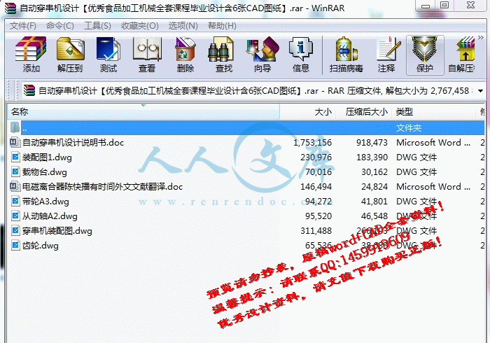
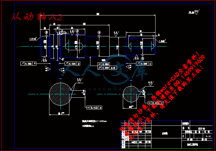
从动轴A2.dwg

带轮A3.dwg

穿串机装配图.dwg

自动穿串机设计说明书.doc

装配图1.dwg

载物台.dwg

齿轮.dwg

 摘要

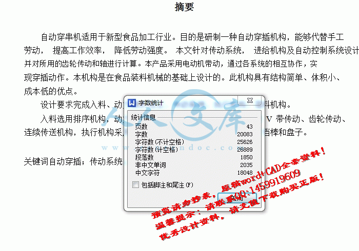
自动穿串机适用于新型食品加工行业。目的是研制一种自动穿插机构,能够代替手工

劳动, 提高工作效率, 降低劳动强度。 本文针对传动系统, 进给机构及自动控制系统设计。

并对所用的齿轮传动和轴进行计算。本产品采用电动机带动,通过各系统的相互协作,实

现穿插动作。本机构是在食品装料机械的基础上设计的。此机构具有结构简单、体积小、

成本低的优点。

设计要求完成入料、动力源的选定、传动系统、执行机构、落料机构。

入料选用排序机构,动力源的选定选用电动机,传动系统采用 V 带传动、齿轮传动、

连续传送机构,执行机构采用插签机构、压盘装置,落料机构一个挡棒和盘子。

关键词自动穿插;传动系统;自动控制系统

Abstract

Automatic wear string machine is suitable for new food processing industry. Purpose is to

develop a kind of automatic thrust institution, can replace manual labor, improve work efficiency

and reduce labor intensity. Based on transmission system, lathe and automatic control system

design. And on the gear and axis. This product adopts motor driving through the cooperation and

realizing the system into action. The agency is in charge of food machinery based on the design.

The agency has simple structure, small volume, low cost advantage.

Complete the design requirements of power and selected, transmission system, actuators,

blanking institutions.

The ranking selection, the selected chooses motor, power transmission adopts the V belt

transmission, gear, continuous transmission, actuator adopts inserted sign institutions, pressure

plate blanking institution, a block sticks and plates.

Keywordsautomatically alternates, Transmission systems, Automatic control system

目录(论文 )

1 绪论……………………………………………………………………………………………..1

1.1 序言…………………………………………………...………………………………….1

1.2 自动穿串机的设计思路……………………………………………………………….1

2 自动穿串机各机构的选择及设计设计思路………………………………………………......2

2.1 入料机构的选择及设计……………………………………………………………….2

2.2 振动筛的设计………………………………………………………………………………2

2.3 穿插机构的设计…………………………………………………………………….…..5

2.3.1 插签机构……………………………………………………………………………..5

2.3.2 压盘装置……………………………………………………………………………..5

2.4 落料机构的设计………………………………………………………………………...6

3 轴承的选定………………………………………………………………………………..…....7

3.1 概述………………………………………………………………………………………7

3.2 滚动轴承的主要类型、特点和代号…………………………………………………8

3.3 轴承的寿命计算…………………………………………………………………….…10

3.3.1 滚动轴承的基本额定寿命……………………………………………………..…..10

3.3.2 基本额定动负荷………………..………………………………………………..…..10

3.3.3 寿命计算公式 …………………….………………………………………………....11

3.3.4 额定寿命的修正……………..………………………………………………..…..11

3.3.5 滚动轴承的当量动载荷……………………………………………………..…..11

3.3.6 角接触轴承的计算…………...……………………………………………..…..12

3.3.7 主动轴轴承的校核……………………………..………………………………..…..12

3.3.8 从动轴轴承的校核………………………..……………………………………..…..13

4 传动机构设计………………………………………………………………………………....14

4.1 传动系统的选择……………………………………………………...…………..……14

4.1.1 带传动的类型和特点………………………..…………………………………..…..14

4.1.2V 带传动的设计………………………..………………………………………..…..15

4.2 电动机的选择 ………………………………...……………………….....………………18

4.2.1 电动机类型和结构的选择………………………..……………………………..…..18

4.2.2 电动机功率的选择………………………..……………………………………..…..18

4.2.3 确定电动机转速………………………..………………………………………..…..18

4.2.4 电动机型号的确定………………………..……………………………………..…..18

4.3 齿轮传动的设计…………………………....………………………...…………..……19

4.3.1 选择齿轮材料并确定许应应力………………………..………………………..…..19

4.3.2 按齿面接触强度设计计算………………………..……..……………………..…..19

4.4 传动装置运动、动力参数计算 ……………...………………………...………..………21

4.4.1 总传动比的确定………………………..……..…………………………..…..…..21

4.4.2 分配各级传动比………………………..……..………………………..……..…..21

4.4.3 计算各轴转速 ………………………..……..…………………………………...…..21

4.4.4 计算各轴的功率………………………..……..…………………..…………..…..21

4.4.5 计算各轴转矩………………………..……..……………………..………..…..21

4.4.6 传动装置运动、动力参数汇总表………………………..…………………..…..22

4.5 轴的设计计算 ……………...…………………………………………...……………..…22

4.5.1 输入轴的设计计算………………………..……..….……………..………..…..22

4.5.2 输出轴的设计计算………………………..…………………..………..…..25

4.6 输送机的设计 ……………...…………………………………………...……………..…26

5 减速器的选择………………………………………………………………………………....31

5.1 概述……………...………………………………………………..…...…………..……31

5.2 减速器的机构和附件的设计…………...…………………………...……………..…31

5.3 减速器的润滑和密封…………….........……………………………...…………..……32

结论…………………………………………………………...………………………………....33

致谢………………………………………………………………………………………...…....34

参考文献………………………………………………………...……………………………....35

参考文献

[1] 许林成 《包装机械原理与设计》 上海科学技术出版社 1988 年 09 月

[2]吴宗泽主编。机械结构设计。北京:机械工业设计出版社。1988

[3] 邱宣怀 《机械设计》第四版 高等教育出版社 1997 年 7 月

[4](美)米什克主编。机械设计通用手册。河海大学机械学院译。1993

[5].周开勤主编。机械零件手册。第四版。1994

[6]许尚贤编著。机械零件的现代设计方法。1994

[7]陈伸文主编。圆弧齿圆柱齿轮传动。1995

[8]徐灏主编。机械设计手册。北京:机械工业出版社。1995

[9](美)伯尔著。机械分析与机械设计。北京:工业机械出版社,1998

[10] 胡继强 《食品机械与设备》 中国轻工业出版社 1999 年 07 月第 1 版

[11] 任家隆 《机械制造基础》 高等教育出版社 2003 年 3 月

[12] 武予鲁 《带式输送机综合保护装置的工作原理和使用》 煤炭工业出版社 2003年04

[13] 薛焱等 《中文CAD2004基础教程》 清华大学出版社 2003年7月

[14 张春林 《机械创新学设计》 机械工业出版社 2008年7月

内容简介:
Electromagnetic ClutchThe electromagnetic clutch on the power to control the coil with separation of clutch.Electromagnetic clutch can be divided into: dry-ex monolithic electromagnetic clutch, drymore pieces of electromagnetic clutch, wet multiple electromagnetic clutch, magnetic powderclutch, turn to the difference of the electromagnetic clutch, etc.The electromagnetic clutch working mode and can be divided into: combining and power.Dry monolithic electromagnetic clutch: when a current coil magnetic force and bit, clutchengagement in the state, When the bit power coil, clutch in separate chips.Dry more pieces of wet multiple pieces, the principle of electromagnetic clutch: should payan additional several friction torque, the same volume than dry monolithic electromagneticclutch, wet multiple electromagnetic clutch work must have oil cooling and lubrication.Magnetic powder clutch: in active and follower placed between magnetic powder, noelectricity when magnetic powder in loose, magnetic powder, cord with a follower and rotation.Advantages: through adjusting current to adjust torque, allow larger sliding. Faults: largetemperature difference on the slide, relatively high pricesTurn bad type electromagnetic clutch: clutch, Lord, there must be a part from the rotationdifference have torque transmission. Torque depends on the magnetic field strength and speed.Exciter current remain unchanged, speed and torque increases with severe decline, Torqueremain unchanged, exciter current, reduce speed is more serious.Turn bad because of the electromagnetic clutch, driven components without any mechanicalconnection between, wear, magnetic powder consumption, no leakage, adjust current can changespeed variator, make use of the advantages of, this is it. The major disadvantage of clutch rotorof eddy current will generate heat, the heat and speed is proportional to the poor. When the speedof the efficiency is low, the efficiency of the value and the driven shaft speed, which is = n2 /n1Applicable to transmission system, is running conditions, driven and or separation.A separation between with follower, active in a rotation, follower, Active and follower,active state between mating between follower. BringWidely used in machine tools, packaging, printing, textile, light industry, and officeequipment.The electromagnetic clutch commonly used for environmental temperature, humidity - -50% less than 85%, no danger of medium voltage fluctuation, the coil not over the rated voltageof 5%features1. high response: because it is so dry type of torsion, can achieve the convenient quickly.36徐州工程学院毕业设计(论文 )2. good thermal durability strong: and the use of advanced materials, even the use of highfrequency and high, also very durable.3. and assembly easy maintenance: belongs to the ball bearings inside the magnetic coil, sodont need static will also need not use rui remove carbon brush, simple to use.4. indeed, use, although have strong plate shell is not loose, shaking durability.Dry electromagnetic clutch when using ban, otherwise will lead to add oil dropped torque.CautionsThe electromagnetic clutch must be cleaned before installed and remove rust and sundry.The electromagnetic clutch can be installed on the coaxial, also can install, axial shaft mustbe fixed, active part and a follower parts are not permitted to axial shaft kiln, installation, activepart and driven shafts coaxial tolerance between parts should be no more than LMM 0.Wet the electromagnetic clutch work, must add the lubricating oil in the friction betweenlubricating way, by (1) pouring oil lubrication, (2) oil lubrication oil into the bath, the part forabout five times the volume of clutch, (3) axis high-speed and supply lubrication, action shouldadopt high fuel method. AxisTooth type electromagnetic clutch installation, must ensure end tooth have clearancebetween, no running gear grinding phenomenon, but not more than the delta.Electromagnetic clutch and brake for class B insulation, normal temperature of 40 degreesCelsius. When the temperature of the thermal limits does not allow more than 100 degreesCelsius, or coil and friction parts easy damage.Power and control circuit, the power supply for the clutch is generally dc 24 v (except forspecial orders. It consists of single-phase ac voltage phase or by antihypertensive and fullrectifier voltage wave filter, and no power requirements, more than 1.5 times rated powerelectromagnetic clutch. Use half wave rectifying power supply must add free-wheeling diode.Install note1. please complete without water, oil etc. Use dry electromagnetic clutch friction parts, if oilstained with water or other substances, can greatly reduce friction torque, clutch sensitivity willbecome worse, in order to avoid using these situations, please added cover.2. and many places in the dust, please use the shield.3. used to install the clutch long axis size please use JIS0401 H6 or JS6 specifications. Thekey for installation of shaft B1301-1959. Please use JIS by one.4. considering the factors such as the installation of thermal, please select the axial thrust in0.2 MM below.5. and when installation, please will attract gap adjusting mechanical for specified minus20%.6. please make bracket remain lightsome, dont use the clutch bearing heavy pressure.7. and on the screws assembled by using spring-loaded metal, please, and agents to preventslack.Eight, the use of mechanical side frame maintain at the same time, also use wire as terminalboard is connected.Maintenance and maintenance methodIn order to guarantee the electromagnetic clutch uninterrupted operation, must often to itsmaintenance and maintenance:1. often in the electromagnetic clutch of moving part to add lubricant.2 .and regularly check the length of the trip. Bit Because in the clutch running processes,because the profile of the bit wear, dynamic schedule length will be increased. When the bitstroke length than normal, must be adjusted to restore brake and the minimum clearance betweenthe turntable. If the trip length increases to normal bit above, can greatly reduce the attraction.3.and if change the face of brake wear, should adjust and brake the minimum clearancebetween the turntable.37徐州工程学院毕业设计(论文 )4. check the bolt fastening degree, especially to tighten bolts electromagnet bolts and shellelectromagnet, the yoke, magnetic coil of bolt, solenoid bolts and wiring bolts.5.and regularly check the moving parts of mechanical wear, and remove the dust on thesurface of the part and electromagnets flowers and dirt.The basic usage1. connection with sundering: driving parts and the starting position is not installed betweenclutch, stop, start will be driven in connection with the necessary reaction do the action fromcutting.2. each variable on homework: when the situation, this conversion speed, is not closed usingclutch driven gears can place.3. positive &negative: load point of positive &negative switching, cooperate with the clutchis used as turning toward the driver.4. High-frequency operation: in the intermittent operation, quick cycle repeated use ofmotor, OFF the provided ON frequency Co., LTD, therefore, make use of the clutch of rapidresponse, high precision of braking.5.inches of dynamic mechanical began moving and position in the clutch engagement, onlywhen the instantaneous actuatorDedicated to the single screw compressor machine updated the IntroductionAbstract: This paper describes four areas from the existing single-screw machine layout andstructure, and put out the advantages and disadvantages of the list, because of the compressorplant single-screw machine tools and machine tool external Security information, the aboveintroduction there is inevitably one-sided and wrong, and are therefore single-screw compressorfor the production of reference works.First, introduce the layout of machine toolsDecide the size of the compressor displacement of the stars round, screw diameter, mesh sizeand the size of the center distance, so different in diameter screw, machine tool spindle and therotary center are also different. To meet the processing of different diameter screw, single screwCurrently the layout of machine tools in general there are several options.The first is: machine tool rotary tool spindle center and the center distance for the fixedMachine tool rotary tool spindle center and the center distance for the fixed, can not adjustthe center distance. Processing of several of the screw diameter on the center distance requiredseveral different specifications of the machine.Advantages: simple structure of the machine.Disadvantage: each machine can only process a specification of the screw, when the marketon a certain specification requirements when the screw compressor, resulting in a machine, othermachine idle.The second: the machine tool spindle box for rotaryProcessing screw machine according to the size of the diameter at the processing before apoint of rotating spindle box. Spindle box that the machine can turn on a machine at the above-mentioned article on the use of the improvements, with the first structure of a machine tool isbasically the same.Advantages: the structure of machine tool easy to adapt to a variety of specifications of theprocessing screw.One disadvantage: after the rotating spindle box and the tool spindle turning center linedistance between the center line of accurate measurement difficult.2 disadvantage: after the rotating spindle spindle box and the front surface of the rotary cuttercenterline distance between the reduction of the larger diameter of the screw processing is limited.The third: the machine tool spindle box for horizontal mobileBox at the bottom of the spindle and the base there is arranged between the rectangular38徐州工程学院毕业设计(论文 )sliding rail, spindle box perpendicular to the direction of movement of spindle centerline andperpendicular to the centerline of the tool rotation. Through the power of the spindle box splineshaft to the base of the tool feed mechanism.Screw diameter, according to the size of the processing in the processing of the previousround by hand to the body put into the screw spindle box moved to the appropriate location, andthen screw the spindle box on a fixed base. Spindle box available from the mobile Gratingdetection, position error 0.005mm.Horizontal spindle box can be used as a mobile machine can process diameter 95 385mm any kind between the screw specifications. 95 385mm processing because of the diameter of the screw, causing the front surfaceand the tool spindle rotation the distance between the center line of the margin is too large, theactual application in the design specifications of the machine into two, a 95 205mm machinescrew diameter Another 180 385mm machine screw diameter.Advantages: a variety of tools to adapt to the specifications of the processing screw, eachscrew specifications need not be provided with the appropriate machine tools.Disadvantage: the structure of machine tools and machine tool assembly of the two kinds ofmore complex machine tools, machine tools than the cost of two kinds of machine tools before thehigh.Second, introduce the structure of machine tool spindleThe level of machine tool spindle box on the main axis and the base of the vertical axisdetermines the degree of precision was the precision screw machining, at the same time screwcompressor at a speed of thousands of high-speed rotary switch, the accuracy of the screw will beless so that the compressor have a fever, vibration, low efficiency, such as wear and tear situationquickly.Currently available single-screw machine spindle structure of the program has the followingtwo.The first is: bearing radial clearance is not adjustable spindle structureBefore spindle bearing out the use of one pairs of cylindrical roller bearings and thrust ballbearing combination of both, the main use of double row cylindrical roller bearings under radialcutting force, the use of two ball bearings to bear axial thrust cutting force.After the general adoption of the spindle bearings out one pairs of cylindrical roller bearingsor a ball bearing to the heart.Main advantages of this structure: the main axis of the processing and assembly of simple,low cost.One disadvantage: because the main axis of the radial bearing clearance can not be adjustedso poor precision spindle. Although the use of bearings and shaft diameter fit to eliminate theradial bearing clearance, but each bearing diameter and radial clearance is not a fixed value, so itis difficult to design and processing to the quasi-axial-radial and bearings with bore tolerances.2 disadvantage: it is very difficult to buy in the market of domestically produced or imported,C, D or P4, P5 class thrust ball bearings, machine tool manufacturing plant commonly usedalternative to the use of ordinary class bearings, which also affected the accuracy of the enhancespindle.Bearing radial clearance adjustable spindle structure do not apply to the general accuracy ofthe general machine tools, does not apply to require a higher accuracy of the spindle of machinetools.The second: the radial bearing clearance adjustable spindle structureBefore the adoption of a spindle bearing P4 class of double row tapered hole cylindricalroller bearings and a P4-class double row ball bearing thrust to the combination of heart. The useof the spindle hole of the double row tapered cylindrical roller bearings under radial cutting force,the use of double row ball bearing thrust to the heart to bear part of the axial and radial cutting39force cutting force.徐州工程学院毕业设计(论文 )Spindle bearings generally used after a P5 class of double row tapered hole cylindrical rollerbearings.Double row tapered hole cylindrical roller bearings with inner ring and shaft are tapered 1:12,bearing lock nut with a round led a bearing in the axial displacement of the inner ring bearings andexpansion, to reduce or eliminate Bearing radial clearance purposes.Main structure of such advantages: high precision spindle. At the front spindle diameter230mm noodle on the end measuring spindle Beat value of 0.010mm. 230mm cylindricalspindle at the front end on the radial axis measurement value of Beat 0.005mm. The secondstructure of the spindle of a precision spindle accuracy than the first about 50% improve.Main disadvantage of this structure:The principal axis of the more complicated process, the spindle assembly also has theexperience necessary to make the workers to operate the spindle achieve the desired numericalaccuracy.Third, the depth of the tool feed controlRequired different processing screw diameter spiral groove depth is also different from thedepth of the spiral groove mm from dozens to more than 100 millimeters range around the toolinto the institutions required to feed the thousands of ring rotation in order to achieve a screwmachining .Feed because of the tool in the tool rotating at the same time achieve motion feed, so on anumber of general machine tools used in mechanical, electrical control method of depth of cutdoes not apply to single-screw machine.Single screw machine tools give agencies into the following different methods can be feed tocontrol the depth of purpose.The first is: friction clutch and electrical switches to control the depth of the tool feedIts principle is to control depth of cut increases the tool cutter feed mechanism increases theload torque so that the tool feeding mechanism of the friction transmission chain slipping clutch, amechanical linkage concurrent silent trigger electrical switches, optical signal prompted operator,when manual operator to disconnect the tool into the power sector.The advantages of this control method are: the control method is simple and spare partsprocessing and operational power from the impact of a sudden.Disadvantage are: processing of different diameter screw to adjust the clutch friction discspressed the preload spring.Material because of the density of each screw, and the hardness of the existence of subtledifferences in the degree of cutting tools sharp differences exist, thus the accuracy of this controlmethod was not too accurate, may lead to screw spiral groove depth tolerance is too large.The second: use of an electromagnetic clutch, encoder control tool into the mix to the depthofTool feed system, equipped with electromagnetic clutch and a tool for detecting the numberof rotating ring gear and a gun encoder.It is a tool of control principle hand screw surface encoder to start counting switch, then startcounting counting device, when the rotary tool to pre-set number of laps when the cutting depth isreached, the electromagnetic clutch automatic off open to the power tool into the concurrent silent,optical signal parts prompted the operator has finished processing.The detection device through the digital display shows the number of feed circles or feed.Torn off and the electromagnetic clutch, the tool does not only into the rotation with the verticalshaft to the sport.The advantages of this control method are: the depth of the spiral groove screw tolerancecontrol more accurate, because of several significant table shows the depth of processing, or wanta few laps and the depth of processing or circle the number of operations is also very intuitive and40user-friendly.徐州工程学院毕业设计(论文 )Disadvantage are: electrical control of machine tools at the same time more complex parts ofthis control method at the processing plant, if a sudden power failure, the prior data set will be lost.If you add in the electrical control of the battery to power at the early-dimensional detectiondevices to maintain the job, the problem can be resolved.Four, the control gear drive spaceSingle screw machine screw in the processing, due to the spiral groove in the rotary tool andthe workpiece rotation to complete the synthesis process. Just cut into the workpiece when thetool in the tangential direction of rotation has been going on a greater resistance knife, cutting toolat the workpiece to be cut when the role of the spiral groove, the tool in the tangential direction ofrotation has been going up against a smaller knife and even by the spiral groove thrust workpiece.Because there is a box-hole processing machine tool, gear and other processing error, the toolaxis of rotation of the drive space is too large, large amount of so-called open.Detect drive way too much space is a fixed power input shaft and output shaft rotationshaking, in the case of the transmission structure of conventional design and manufacture ofmachine tools, the transmission output shaft angle space at more than ten degrees to the dozens ofdegrees. Transmission gap caused by too large spiral screw groove surface then there is obviousmarks, thus affecting the machining accuracy of the screw.Upon completion of the assembly machine tool axis of rotation of the drive space is too large,in fact are subject to various errors gear, creating a backlash of the gear is too large.Machine tools in the mechanical transmission gear are used regardless of the accuracy of afew of the class, the designers take into account the gear manufacturing error, processing error boxcenter distance, temperature, lubricating oil film thickness, the assembly error and other factors,machine design must ensure that transmission gear A certain amount of backlash, backlash decidethe size of the gear tooth thickness tolerance size.Single-screw machine has the Main Drive from other machine tool structure specificity. Inorder to reduce transmission or reasonable gap single-screw machine tools currently used by thefollowing two ways.The first is: the installation at the output shaft brakeTool at the output shaft rotating the location of cylindrical symmetry with radial brake, brakestand up to the tool front-end of the cylindrical rotary output shaft, brake for spring preload.The working principle of the brake is generated by the friction brake to increase the outputshaft damping, reducing the sensitivity of the rotation axis.Are: brake and easy does not change the structure of the original machine tool structure, themethod of indirect reduction to achieve the purpose of drive space, in practical applications thereis a certain effect.One disadvantage: the pre-spring brake tool because of the cylindrical output shaft to exert agreater radial force, in fact increases the load machine torque, resulting in increased motor powerat the same time gears, bearings to accelerate wear and tear.Disadvantage 2: pre-spring brake because of the output shaft of the cylindrical tool to exert agreater radial force on the possible geometry of the tool output shaft a negative impact onaccuracy.Conclusion: This article describes four areas from existing single-screw machine layout andstructure, and put out the advantages and disadvantages of the list, because of the compressorplant single-screw machine tools and machine tool external Security information, the aboveintroduction there is inevitably one-sided and wrong, and are therefore single-screw compressorfor the production of reference works.41徐州工程学院毕业设计电磁离合器(论文 )电磁离合器靠线圈的通断电来控制离合器 的接合与分离。电磁离合器可分为:干式单片电磁离合器,干式多片电磁离合器,湿式多片电离合器,磁粉离合器,转差式电磁离合器等。电磁离合器工作方式又可分为:通电结合和断电结合。磁干式单片电磁离合器: 线圈通电时产生磁力吸合线圈断电时“衔铁 ”弹回,离合器处于分离状态。“衔铁 ”片, 离合器处于接合状 态;干式多片湿式多片电磁离合器:原理同上,另外增加几个摩擦付,同等体积转矩比干式单片电磁离合器大,湿式多片电磁离合器工作时必须有油液冷却和润滑。磁粉离合器:在主动与从动件之间放置磁粉,不通电时磁粉处于松散状态,通时磁粉结合,主动件与从动件同时转动。优点:可通过调节电流来调节转矩,允许大滑差。缺点:较大滑差时温升较大,相对价格高转差式电磁离合器:离合器工作时,主、从部分必须存在某一转速差才有转矩递。转矩大小取决于磁场强度和转速差。励磁电流保持不变,转速随转矩增加而剧下降;转矩保持不变,励磁电流减少,转速减少得更加严重。转差式电磁离合器由于主、从动部件间无任何机械连接,无磨损消耗,无磁粉电较传烈泄漏,无冲击,调整励磁电流可以改变转速,作无级变速器 使用,这是它的优点。该离合器的主要缺点是转子中的涡流会产生热量, 该热量与转速差成正比。 低速运转时效率很低,效率值为主、从动轴的转速比,即n2/n1适用于高频动作的机械传动系统, 可在主动部分运转的情况下, 使从动部分与动部分结合或分离。主动件与从动件之间处于分离状态时,主动件转动,从动件静止;主动件与从件之间处于接合状态,主动间带去从动件转动。广泛适用于机床、包装、印刷、纺织、轻工、及办公设备中。电磁离合器一般用于环境温度2050,湿度小于85,无爆炸危险的介质中,其线圈电压波动不超过额定电压的5特点1、高速响应:因为是干式类所以扭力的传达很快,可以达到便捷的动作。2、耐久性强:散热情况良好,而且使用了高级的材料,即使是高频率,高能的使用,也十分耐用.42的主动量徐州工程学院毕业设计(论文 )3、组装维护容易:属于滚珠轴承内藏的磁场线圈静止形,所以不需要将中蕊出也不必利用碳刷,使用简单。4、动作确实:使用板状弹片,虽有强烈震动亦不会产生松动,耐久性佳。干式电磁离合器使用时禁止加入油脂,否则将导致扭矩下降。使用注意事项电磁离合器安装前必须清洗干净,去除防锈脂及杂物。取电磁离合器可同轴安装,也可以对轴安装,轴向必须固定,主动部分与从动部分均不允许有轴向窜动,对轴安装时,主动部份与从动部份轴之间同轴度应不大于 0.lmm。湿式电磁离合器工作时,必须在摩擦片间加润滑油,润滑方式采用(1)分浇油润滑;(2)油浴润滑,其浸入油中的部分约为离合器体积的 5 倍;(3)轴心供油润滑,在高速和高频动作时应采用轴心供油方法。牙嵌式电磁离合器安装时,必须保证端面齿之间有一定间隙,使空转时无磨齿现象,但不得大于值。电磁离合器及制动器为 B 级绝缘,正常温升 40。极限热平衡时的工作温度不允许超过 100,否则线圈与摩擦部分容易发生破坏。电源及控制线路,离合器电源为一般为直流 24 伏(特殊定货除外)。它由三相或单相交流电压经降压和全波整流得到,无稳压及滤波要求,电源功率要大于电磁离合器额定功率 1.5 倍以上。使用半波整流电源必须加装续流二极管。安装注意事项1、请在完全没有水分、油分等的状态下使用干式电磁离合器,如果摩擦部位有水分或油分等物质,会使摩擦扭力大为降低,离合器的灵敏度也会变差,为了在用上避免这些情况,请加设罩盖。2、在尘埃很多的场所使用时,请使用防护罩。3、用来安装离合器的长轴尺寸请使用JIS0401 H6 或 JS6的规格。用于安装轴的键请使用JIS B1301-1959所规定的其中一种。4、考虑到热膨胀等因素,安装轴的推力请选择在0.2MM以下。5、安装时请在机械上将吸引间隙调整为规定值的正负20% 以内。6、请使托架保持轻盈,不要使用离合器的轴承承受过重的压力。7、关于组装用的螺钉,请利用弹簧金属片、接著剂等进行防止松弛的处理。8、利用机械侧的框架维持引线的同时,还要利用端子板等进行确实的连接。保养与维护方法为了保证电磁离合器不间断的运行,必须要经常对其进行维护和保养:1、经常在电磁离合器的可动部分添加润滑剂。沾使2、 定期检查衔铁行程的长度。因为在离合器的运行过程中,由于剖动面的磨衔铁的行程长度将增大。当衔铁行程长度达不到正常值时,必须进行调整,以恢复43损,制徐州工程学院毕业设计(论文 )动面与转盘之间的最小间隙。 如果衔铁行程长度增大到正常值以上, 就可能大大降吸力。3、如果更换了磨损的制动面,应重新适当调整制动面与转盘之间的最小间隙。低4、 经常检查螺栓的紧固程度,特别要拧紧电磁铁 的螺栓、电磁铁与外壳的螺栓、磁轭的螺栓、电磁铁线圈的螺栓和接线螺栓。5、定期检查可动部件的机械磨损情况,并清除电磁铁零件表面的灰尘、花毛污垢。基本使用方法1连接与切离动作:驱动部位与起动部位之间安装离合器,则不须停止驱动起动处会依必要反应做连接与切离的动作.2变速:作业途中时有相互转换速度的情形、此时使用离合器、则不须关闭动处即可变速.3正反转:负荷点的正反转切换时、配合离合器使用则驱动外只要顺向回转可 .和处,驱即4高频运转:在快速循环中的断续运转、反复利用马达上的的频度有限、因此使用离合器、使之迅速反应、高精度的制动.ON 、OFF 所提供5.寸动:机械开始作动与位置接合时、只须以离合器瞬时作动即可专门为单螺杆压缩机的更新作简介摘要:本文从四个方面介绍了国内现有单螺杆加工机床的布局和结构,并把优缺点一一列举出来,由于压缩机生产厂的单螺杆加工机床和机床资料对外保密,以上介绍难免有片面、不妥之处,因此仅供单螺杆压缩机生产厂参考。一、介绍机床的布局压缩机排气量的大小决定了星轮、螺杆直径的大小和啮合中心距的大小,因此螺杆直径的不同,机床的主轴与刀具的回转中心也不同。为满足加工不同直径的螺杆,目前国内单螺杆加工机床的布局大致有以下几种方案。第一种:机床的主轴与刀具回转中心的中心距为固定式机床的主轴与刀具回转中心的中心距为固定式,中心距不可调整。加工几种直径的螺杆就需要几种中心距规格不同的机床。优点:机床的结构简单。缺点:每种机床只能加工一种规格的螺杆,当市场上某种规格的压缩机螺杆需要量大时,造成一台机床加工,其他机床闲置。第二
温馨提示:
1: 本站所有资源如无特殊说明,都需要本地电脑安装OFFICE2007和PDF阅读器。图纸软件为CAD,CAXA,PROE,UG,SolidWorks等.压缩文件请下载最新的WinRAR软件解压。
2: 本站的文档不包含任何第三方提供的附件图纸等,如果需要附件,请联系上传者。文件的所有权益归上传用户所有。
3.本站RAR压缩包中若带图纸,网页内容里面会有图纸预览,若没有图纸预览就没有图纸。
4. 未经权益所有人同意不得将文件中的内容挪作商业或盈利用途。
5. 人人文库网仅提供信息存储空间,仅对用户上传内容的表现方式做保护处理,对用户上传分享的文档内容本身不做任何修改或编辑,并不能对任何下载内容负责。
6. 下载文件中如有侵权或不适当内容,请与我们联系,我们立即纠正。
7. 本站不保证下载资源的准确性、安全性和完整性, 同时也不承担用户因使用这些下载资源对自己和他人造成任何形式的伤害或损失。
提示  人人文库网所有资源均是用户自行上传分享,仅供网友学习交流,未经上传用户书面授权,请勿作他用。
关于本文
本文标题:自动穿串机的设计【优秀食品加工机械全套课程毕业设计含6张CAD图纸】
链接地址:https://www.renrendoc.com/p-479198.html

官方联系方式

2:不支持迅雷下载,请使用浏览器下载   
3:不支持QQ浏览器下载,请用其他浏览器   
4:下载后的文档和图纸-无水印   
5:文档经过压缩,下载后原文更清晰   
关于我们 - 网站声明 - 网站地图 - 资源地图 - 友情链接 - 网站客服 - 联系我们

网站客服QQ:2881952447     

copyright@ 2020-2025  renrendoc.com 人人文库版权所有   联系电话:400-852-1180

备案号:蜀ICP备2022000484号-2       经营许可证: 川B2-20220663       公网安备川公网安备: 51019002004831号

本站为文档C2C交易模式,即用户上传的文档直接被用户下载,本站只是中间服务平台,本站所有文档下载所得的收益归上传人(含作者)所有。人人文库网仅提供信息存储空间,仅对用户上传内容的表现方式做保护处理,对上载内容本身不做任何修改或编辑。若文档所含内容侵犯了您的版权或隐私,请立即通知人人文库网,我们立即给予删除!