洗涤剂瓶嘴注射模设计【优秀含20张CAD图纸+塑料模具全套毕业设计】【侧抽芯】
收藏
资源目录

压缩包内文档预览:
编号:479266
类型:共享资源
大小:1.45MB
格式:ZIP
上传时间:2015-10-07
上传人:小***
认证信息
个人认证
林**(实名认证)
福建
IP属地:福建
45
积分
- 关 键 词:
-
洗涤剂
注射
设计
优秀
优良
20
cad
图纸
塑料模具
全套
毕业设计
侧抽芯
- 资源描述:
-
!【详情如下】【注塑塑料模具课题】CAD图纸+word设计说明书.doc[16000字,33页]【需要咨询购买全套设计请加QQ97666224】.bat
主流道衬套.dwg
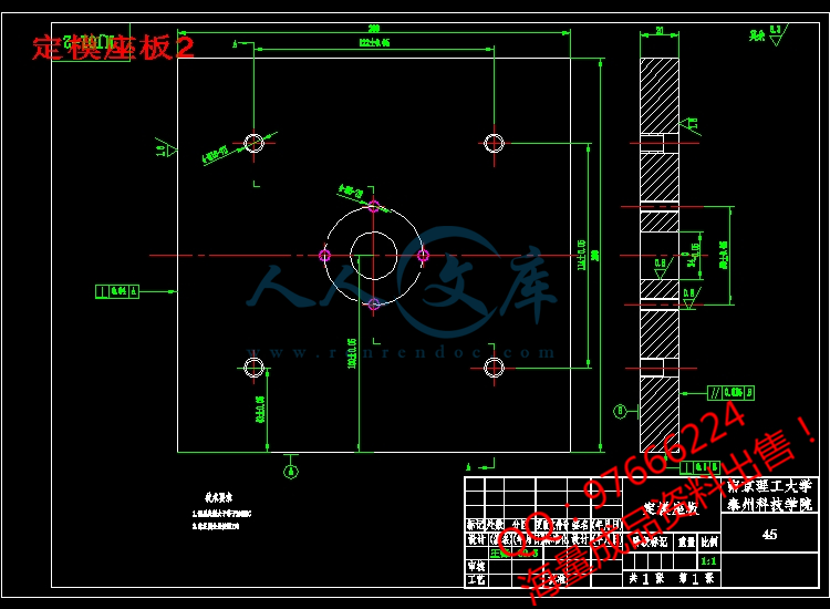
动模座板2.dwg
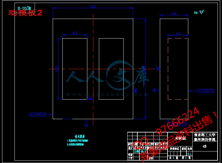
动模板2.dwg
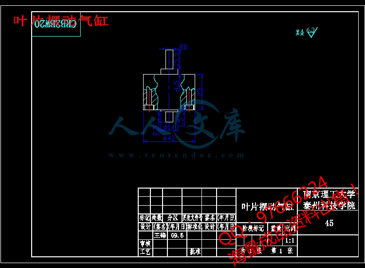
叶片摆动气缸.dwg
型腔板2.dwg
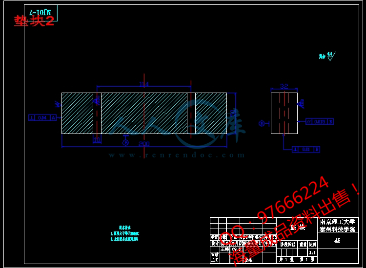
垫块2.dwg
复位杆.dwg
定模座板2.dwg
定模板2.dwg
导套.dwg
拉料杆.dwg
推杆.dwg
推板2.dwg
推板固定板2.dwg
斜导柱.dwg
直头导柱.dwg
装配图.dwg
零件.dwg
齿条.dwg
齿轮轴.dwg
外文翻译.doc
开题报告.doc
设计说明书.doc[16000字,33页]
目 录
1 引言1
1.1 模具工业的重要性及发展趋势1
1.2 塑料及塑料模具的现代设计与制造1
1.3 塑料注塑模技术2
2 塑料注射模具的设计步骤4
2.1 塑料件的工艺性分析4
2.2 洗涤剂瓶嘴材料的选择4
2.3 绘制模具装配草图4
2.4 对零件进行造型设计并绘制工程图5
2.5 课程任务要求6
3. 方案分析与设计7
4. 洗涤剂瓶嘴注射模的详细设计8
4.1 塑料注射成型机的选择8
4.2 注射模具分型面的选择11
4.3 注模具浇注系统的设计12
4.4 注射模具成型零件和模体的设计16
4.5 注射模具的顶出机构的设计19
4.6 塑料注射模具的温度调节系统设计23
4.7 模具结构设计25
5 注射模加工工艺设计26
5.1 坯料确定26
5.2 模板的平面加工26
6 塑料注射模具型腔常用加工方法及设备28
6.1 型腔的普通切削加工方法及设备28
6.2 型腔的特种加工28
结束语30
致谢31
参考文献32
本文根据工程实际的需要完成洗涤剂瓶嘴的注射模具设计。在设计中采用聚苯乙烯塑料注射而成型,成型方式为一模两腔,该论文具体分析了产品的工艺性,确定了所采用塑料的工艺参数和所采用的成型设备,确定了模具制作的总体方案,分析并解决了模具的总体结构和各工作部分的具体结构,并进行了一些必要的尺寸计算和强度的校核。该论文还对分型面、浇注系统和脱模机构进行了分析设计,完成了模具工程图设计,最后进行了主要零件加工工艺设计。
关键词 注射模 成型 工艺性 设计
毕业设计说明书(论文)外文摘要
Title a Mouth of the Rinse Injection Molding Design
Abstract
The present paper actual needs to complete according to the project accomplish the a Mouth of the Rinse injection molding design. Uses the polyethylene plastic injection in the design to take shape, the formation way is a mold two cavity, this paper concrete study product's technology capability, had determined uses the formation equipment which the plastic the technological parameter and uses, had determined the mold manufactures the overall concept, analyzed and has solved mold's gross structure and each effective range concrete structure, and has carried on some essential size computation and the intensity examination. This paper also halved the profile, the gating system and the mold emptier has carried on the analysis design, has completed the mold engineering plat design.
Keywords Injects the mold Formation Technology capability Design


- 内容简介:
-
南京理工大学泰州科技学院 毕业设计 (论文 )外文资料翻译 系 部: 机械工程系 专 业: 机械工程及自动化 姓 名: 王 锋 学 号: 05010230 外文出处: 中国机械 资讯网 BBS.CMIW.CN 附 件: 1.外文资料翻译译文; 2.外文原文。 指导教师评语: 译文 基本符合翻译原文 ,个别词汇不符合语境。 语句较为通顺 , 条理比较清楚 ,专业用语翻译 基本恰当 , 符合中文语法 ,整体翻译质量较好 。 签名: 年 月 日 nts附件 1:外文资 料翻译译文 在注塑模应用方面,外形电铸 镍的技术注释 摘要 在过去几年 , 快速成型技术及快速模具 在 发达国家已广泛 应用。 在这篇文章中 ,作为一种 范例, 分析电芯塑料注射模具 。 通过快速成型 , 利用差分系统 得到 镍壳模型 。 主要目的是分析镍 壳 力学特征 , 学习不同方面的金相组织 、 硬度 、 内 压,失败 的 可能 性。以 这些特色的有关参数生产 镍 壳电设备 , 终于 得到了 一个注塑模具核心 部分。 关键词 : 电镀; 电制; 显微组织; 镍 文章概要 1. 引言 2. 注塑模具制造过程 3. 电 铸 壳获取 : 设备 4. 获得硬度 5. 金相组织 6. 内压 7. 测试的注塑模具 8. 结论 1引言 现代工业遇到的最重要的挑战 之一 是 在很短的时间内向消费者 提供更好的产品 。 因此 ,现代工业必须有更 强 的竞争性和 适应更合理的 生产成本 。 毫无疑问 , 结合时间 和 质量并不容易 ,因为他们经常互相 变换。 生产 系统的 科技进步 , 在方式将可更有效和可行的 促进 组合 ,例如 ,如果是演化的观测系统和注塑技术、我们得出的结论是事实上 可以用很少的时间和高质量把新产品推向市场。 在模具制造领域 中,先进的 快速模具制造技术有可能改善设计和制造过程注入部分 。 快速模具制造技术基本上是由程序集 中组成, 在短短的时间里 , 以 可接受的精度水平 使 我们获取小型系列 的 塑料模具零件 。 其应用领域不仅包括制作塑胶件注 ,而且 他们研制并 创造了最高产量 。 nts本文包括在广泛试图研究确定分析测试和建议 的 科研第一线 , 在产业层次形成从注塑模具获取镍 壳 核心的可能性 , 同时 用 差分模型快速成型设备取得了初步的模型 。 也将不得不说 , 无数业内人士事前并没有应用任何新电铸技术 , 但 很 大程度上 ,在 快速模具的生产技术上使用这种试图调查研究工作 ., 运用所有准确 , 制度化的方式方法并提出了工作 。 2注塑模具制造过程 核心是透过电进程 的 镍壳 。 这是一个主管充满金属环氧树脂 的 一核心板块 。 模具 (图 1)制造 时可以 直接注射 A 型多用标本 , 确定 SO3167 标准的甲状旁腺恩 目 的是要确定这个试样的力学性能 和通过 常规手段收集工业材料 。 图 1 注塑模具制造与电核心 根据这一方法研制工作 , 该阶段取得核心有以下几方面 : (一 ) CAD 系统预期目标 的 设计 (二 ) 快速原型设备制造模型 (频分多路复用 )。 该材料将 被用于 ABS 塑料 (三 ) 以 以往的模式生产事前已经涂了导电涂料 的 镍电壳 (必须有导 电 ) (四 ) 从模型 中 清理壳牌 (五 ) 生产背面填 充着 随着铜管与冷冻槽 流动具有 抗高温壳牌环氧树脂 的 核 心 注塑模具有两个空洞 , 他们一个是电加工的核心 ,另 一 个 是直接在 机械上 移动压板 。 因此 , 它获得了与同一工具及同一工艺条件同时 在空洞里 注入两种不同 的标本 制 造 技术 。 3 电铸壳获取:设备 电镀是一个电化学过程中的化学变化 , 当电流通过 , 它起源于电解质 。 该电解槽是由金属盐 溶液 淹没两个电极 , 一个阳极 (镍 )、阴极 (示范 )。 通过来自 一定强 度nts的 直流 电。 当电流流经电路 , 目前在溶液 中 金属离子转化为原子 ,堆积于 阴极 或多或少的创造沉淀层。 这项工作采用 的 镀液是由镍、磺酸集中在 400 毫升 /公升 , 氯化镍 (10微克 /公升 )、硼酸 (50微克 /公升 ),allbrite SLA (30立方厘米 /公升 ),703allbrite(2立方厘米 /公升 )。 这种 合成物的 选择主要 取决于 我们打算 的应 用类型 即注塑模具 , 即使注射了玻璃纤维 。 磺酸镍让我们获得可以接受的壳 内压 (测试结果 , 不同工艺条件 ,不高于 50兆帕 和 2兆帕左右最佳条件 )。 不过这种程度的内部压力也是使用添加剂Allbrite SLA 强硝酸 脂、甲醛水溶液 产生 的 后果 。 这种添加剂当允许较小壳 颗粒 增加阻力 。 703allbrite 是降解水溶液以减少表面 腐 蚀 。 氯化镍 ,尽管 内压有害, 增强导电溶液 中的 金属均匀分布在阴极 。 硼酸作为 pH 值的缓冲 。 一旦已确定浴 ,有效验的 参数测试 改变 不同条件过程的电流密度 (在 1至 22a/立方分米 ), 温度 (35至 55)和 pH 值 , 部分 的 改变镀液组成 。 4获得硬度 在 测试期间已获得一个非常有趣的结论 , 对不同程度硬度的 镍壳 一直保持在相当高的稳定价值 。 在 图 2, 在 pH4 0.2, 摄氏 45时, 可以观察到电流密度值为2.5 和 22 之间 。 硬度值 的范围 从高压 540 至 580。 如果 pH值 降 为 3.5, 气温下降55, 硬度值 的范围从 高压 520 以 上至 高压 560 以下。由 磺酸镍组成 的 这一特点使得测试不同于其他传统业务 , 观念 是 允许经营范围更广 ; 然而这种有限性的将取决于其他因素 。 例如内应力 , 因为其工作状 态 可能在某些变性的 pH 值、电流密度和温度 下。 在另一方面 , 传统 的硬度介于 200-250 高压磺酸浴 , 远 低于在测试中获得的。有必要 要考虑到对 于 注塑模具 , 接受 300 高压硬度 。 其中最常见的材料就可以找到注塑模具钢 (高压 290), 积分硬化钢 (高压 520-595), casehardened 钢 (高压760-800)等 。 这样可以观察到中高幅度硬度水平 的 镍 壳 注塑模具材料 , 有偿壳牌是反对 用 低延性的环氧树脂填充 。 因为注塑是一个内压控 制 进程 , 这也是为什么必须要壳厚度尽可能均匀 (以上最低值 ),避免 重大失误 。 如 图: 图 2 硬度变化与电流密度 4+0.2pH值 45 nts5金相组织 主要是为了改良 而 分析金相结构、电流密度、温度值 。 样品分析、横向 部分 (垂直于沉积 )为 实现准备便捷 , 树脂 被 方便的封装在 含有 硝酸 , 醋酸混合物的瓶子 ,进行每隔 15, 25, 40, 50 秒 收盘后擦拭 。 为了事后在奥林匹斯金相显微镜碲 下 观察 PME3-ADL 3.3/10 。 在评论文中的照片之前,有必要讨论用 差分快速成型机械 制造 逐层贯通 的 熔融塑料 (ABS) 壳模具。 每一层挤出模具留下的螺纹直径约 0.15 毫米即横向和纵向的 中间媒介。 因此 ,在机器 的 主要 表面可 以观察到薄线标明的道路 。 这些线路将作为参考解决水平镍重复性显示 。 重复性模式将是一个评估注塑模具基本内容 的 基本要素 : 表面纹理 。 该系列测试表 1 所示 : 表 1 检验系列 系列 pH 温度 ( ) 电流密度 A/mm2 1 4.2 0.2 55 2.22 2 3.9 0.2 45 5.56 3 4.0 0.2 45 10.00 4 4.0 0.2 45 22.22 图 3 显示 第一次 蚀刻 的 系列表面样本 。 它显示了 频分多路复用机的原理, 也就是说有一个良好的重复性 。 它仍无法察觉 圆形的颗粒 结构 , 在 图 4系列 2之后 的第二蚀刻可以观察到一条线道较前明显减少 。 在 图 5系列 2 和 3, 虽然这时 路径很难 查出, 蚀刻 已 开始出现了一批 颗粒 结构 。 另外 , 最黑暗的地方 显示 含有 合成物浴的 蚀刻过程 。 nts 图 3. 系列 1(150) 、蚀刻 1 图 4. 系列 2(300), 蚀刻 2 图 5. 系列 3(300), 蚀刻 2 这一行为表明 , 工作在低电流密度 、 高温 下,壳 以良好的 再现能力 获得粒度即适当 的应用 。 如果 进行了平面沉积的横向分析 , 它可以在所有的样品和一切条件 下测试,沉淀物的 增长结构是 由薄片组成的 (图 6)。 虽然延展性低 ,但是 取得了高机械阻力 。 这 取决于 质量 ,, 首 先存在 添加剂 。 因为磺酸镍 浴 没有添加剂 , 通常制造纤维和非层结构 5。更正 直到近 似于 空值的润湿剂 , 在任何情况下保持层结构表明这种结构的应力消脂 (allbrite 习得 )。 在另一方面 , 据测试根据不同层结构层厚度的计算电流密度 。 图 6. 机横向系列 2 (600), 蚀刻 2. nts6内压 其中一个主要特征是壳 的 应用像 输入 低水平内压 。用 阴极张力法在不同电流密度和镀液温度测量系统 下做 不同的测试 。 钢铁被用来测试与控制自由和固定 (160 毫米长度 宽度 12.7 毫米 ,厚度 0.3 毫米 )。 因为沉积金属 是唯一 允许检测控制机械应变 (拉伸或压应力 )和 计算内压 。 对 于 部分钢铁 来说,从 弹性的角度来看 Stoney 模型 应用 被假定镍 底层 厚度不够 ,表面 影响小 (3 微米 )。 在所有测试 情形 中最佳条件是内部压力 50和极端条件下为 2兆帕 ,为 所需的可接受值 。 最后的结论是在不同的条件 和工作参数 下电镀 浴允许无明显变化内压 。 7测试的注塑模具 试验已 在 各种代表性热塑性材料 中 进行如聚丙烯、 镁 、高密度聚乙烯和 PC。 分析零件的性能 , 如注射大小 、 重量、抗延性僵化 。 测试拉伸力学性能和分析光破坏性 。 这一核心进行约 500 注射量, 其余条件下经受更多 。 一般而言 , 重大分歧都 是 未察觉样本核心之间的行为 。 从加工腔 到 一整套的材料 , 但是在分析 光弹性时 (图七 )发现了两种不同张标本 , 基本上是 取决于 炎热划转、浇注腔的 刚度 。 这种差异说明延性 变化 较突出的部分材料 , 如聚乙烯、 六镁。 图 7 分析光注入标本 在所有分析化验 中 发现高密度聚乙烯管 案例 是一个较低延性标本 。 所得镍核心 , 量化 30%左右 。 在这种情况下 六镁 值也接近 50%。 8结论 经过连续的测试和不同的条件 下 已经清查磺酸镍浴已获准使用添加剂 。 镍壳 将获得一些可以接受的注塑模具的机械性能 。 也就是说 , 重复性好 , 高硬度及良好的机械阻力 。 因而机械层结构不足的部分将取代镍壳的环氧树脂饰面 。 核心为注塑塑造 , 允许注入可接受质量水平中型系列塑料零件 。 nts附件 2:外文原文 (复印件) A technical note on the characterization of electroformed nickel shells for their application to injection molds Abstract The techniques of rapid prototyping and rapid tooling have been widely developed during the last years. In this article, electroforming as a procedure to make cores for plastics injection molds is analysed. Shells are obtained from models manufactured through rapid prototyping using the FDM system. The main objective is to analyze the mechanical features of electroformed nickel shells, studying different aspects related to their metallographic structure, hardness, internal stresses and possible failures, by relating these features to the parameters of production of the shells with an electroforming equipment. Finally a core was tested in an injection mold. Keywords: Electroplating; Electroforming; Microstructure; Nickel Article Outline 1. Introduction 2. Manufacturing process of an injection mold 3. Obtaining an electroformed shell: the equipment 4. Obtained hardness 5. Metallographic structure 6. Internal stresses 7. Test of the injection mold 8. Conclusions 1. Introduction One of the most important challenges with which modern industry comes across is to offer the consumer better products with outstanding variety and time variability (new designs). For this reason, modern industry must ntsbe more and more competitive and it has to produce with acceptable costs. There is no doubt that combining the time variable and the quality variable is not easy because they frequently condition one another; the technological advances in the productive systems are going to permit that combination to be more efficient and feasible in a way that, for example, if it is observed the evolution of the systems and techniques of plastics injection, we arrive at the conclusion that, in fact, it takes less and less time to put a new product on the market and with higher levels of quality. The manufacturing technology of rapid tooling is, in this field, one of those technological advances that makes possible the improvements in the processes of designing and manufacturing injected parts. Rapid tooling techniques are basically composed of a collection of procedures that are going to allow us to obtain a mold of plastic parts, in small or medium series, in a short period of time and with acceptable accuracy levels. Their application is not only included in the field of making plastic injected pieces , however, it is true that it is where they have developed more and where they find the highest output. This paper is included within a wider research line where it attempts to study, define, analyze, test and propose, at an industrial level, the possibility of creating cores for injection molds starting from obtaining electroformed nickel shells, taking as an initial model a prototype made in a FDM rapid prototyping equipment. It also would have to say beforehand that the electroforming technique is not something new because its applications in the industry are countless but this research work has tried to investigate to what extent and under which parameters the use of this technique in the production of rapid molds is technically feasible. All made in an accurate and systematized way of use and proposing a working method. nts2. Manufacturing process of an injection mold The core is formed by a thin nickel shell that is obtained through the electroforming process, and that is filled with an epoxic resin with metallic charge during the integration in the core plate 。 This mold (Fig. 1) permits the direct manufacturing by injection of a type a multiple use specimen, as they are defined by the UNE-EN ISO 3167 standard. The purpose of this specimen is to determine the mechanical properties of a collection of materials representative industry, injected in these tools and its coMParison with the properties obtained by conventional tools. Fig. 1. Manufactured injection mold with electroformed core. The stages to obtain a core, according to the methodology researched in this work, are the following: (a) Design in CAD system of the desired object. (b) Model manufacturing in a rapid prototyping equipment (FDM system). The material used will be an ABS plastic. (c) Manufacturing of a nickel electroformed shell starting from the previous model that has been coated with a conductive paint beforehand (it must have electrical conductivity). (d) Removal of the shell from the model. (e) Production of the core by filling the back of the shell with epoxy resin resistant to high temperatures and with the refrigerating ducts made with copper tubes. The injection mold had two cavities, one of them was the electroformed core and the other was directly machined in the moving platen. Thus, it was obtained, with the same tool and in the same process conditions, to inject ntssimultaneously two specimens in cavities manufactured with different technologies. 3. Obtaining an electroformed shell: the equipment Electrodeposition is an electrochemical process in which a chemical change has its origin within an electrolyte when passing an electric current through it. The electrolytic bath is formed by metal salts with two submerged electrodes, an anode (nickel) and a cathode (model), through which it is made to pass an intensity coming from a DC current. When the current flows through the circuit, the metal ions present in the solution are transformed into atoms that are settled on the cathode creating a more or less uniform deposit layer. The plating bath used in this work is formed by nickel sulfamate and at a concentration of 400 ml/l, nickel chloride (10 g/l), boric acid (50 g/l), Allbrite SLA (30 cc/l) and Allbrite 703 (2 cc/l). The selection of this composition is mainly due to the type of application we intend, that is to say, injection molds, even when the injection is made with fibreglass. Nickel sulfamate allows us to obtain an acceptable level of internal stresses in the shell (the tests gave results, for different process conditions, not superior to 50 MPa and for optimum conditions around 2 MPa). Nevertheless, such level of internal pressure is also a consequence of using as an additive Allbrite SLA, which is a stress reducer constituted by derivatives of toluenesulfonamide and by formaldehyde in aqueous solution. Such additive also favours the increase of the resistance of the shell when permitting a smaller grain. Allbrite 703 is an aqueous solution of biodegradable surface-acting agents that has been utilized to reduce the risk of pitting. Nickel chloride, in spite of being harmful for the internal stresses, is added to enhance the conductivity of the solution and to favour the uniformity in the metallic distribution in the cathode. The boric acid acts as a pH buffer. ntsOnce the bath has been defined, the operative parameters that have been altered for testing different conditions of the process have been the current density (between 1 and 22 A/dm2), the temperature (between 35 and 55 C) and the pH, partially modifying the bath composition. 4. Obtained hardness One of the most interesting conclusions obtained during the tests has been that the level of hardness of the different electroformed shells has remained at rather high and stable values. In Fig. 2, it can be observed the way in which for current density values between 2.5 and 22 A/dm2, the hardness values range from 540 and 580 HV, at pH 4 0.2 and with a temperature of 45 C. If the pH of the bath is reduced at 3.5 and the temperature is 55 C those values are above 520 HV and below 560 HV. This feature makes the tested bath different from other conventional ones composed by nickel sulfamate, allowing to operate with a wider range of values; nevertheless, such operativity will be limited depending on other factors, such as internal stress because its variability may condition the work at certain values of pH, current density or temperature. On the other hand, the hardness of a conventional sulfamate bath is between 200 250 HV, much lower than the one obtained in the tests. It is necessary to take into account that, for an injection mold, the hardness is acceptable starting from 300 HV. Among the most usual materials for injection molds it is possible to find steel for improvement (290 HV), steel for integral hardening (520 595 HV), casehardened steel (760 800 HV), etc., in such a way that it can be observed that the hardness levels of the nickel shells would be within the medium high range of the materials for injection molds. The objection to the low ductility of the shell is compensated in such a way with the epoxy resin filling that would follow it because this is the one responsible for holding inwardly the pressure charges of the processes of plastics injection; this is the reason why it is necessary for the shell ntsto have a thickness as homogeneous as possible (above a minimum value) and with absence of important failures such as pitting. Fig. 2. Hardness variation with current density. pH 4 0.2, T = 45 C. 5. Metallographic structure In order to analyze the metallographic structure, the values of current density and temperature were mainly modified. The samples were analyzed in frontal section and in transversal section (perpendicular to the deposition). For achieving a convenient preparation, they were conveniently encapsulated in resin, polished and etched in different stages with a mixture of acetic acid and nitric acid. The etches are carried out at intervals of 15, 25, 40 and 50 s, after being polished again, in order to be observed afterwards in a metallographic microscope Olympus PME3-ADL 3.3/10. Before going on to comment the photographs shown in this article, it is necessary to say that the models used to manufacture the shells were made in a FDM rapid prototyping machine where the molten plastic material (ABS), that later solidifies, is settled layer by layer. In each layer, the extruder die leaves a thread approximately 0.15 mm in diameter which is compacted horizontal and vertically with the thread settled inmediately after. Thus, in the surface it can be observed thin lines that indicate the roads followed by the head of the machine. These lines are going to act as a reference to indicate the reproducibility level of the nickel settled. The reproducibility of the model is going to be a fundamental element to evaluate a basic aspect of injection molds: the surface texture. The tested series are indicated in Table 1. Table 1. Tested series ntsSeries pH Temperature (C) Current density (A/dm2) 1 4.2 0.2 55 2.22 2 3.9 0.2 45 5.56 3 4.0 0.2 45 10.00 4 4.0 0.2 45 22.22 Fig. 3 illustrates the surface of a sample of the series after the first etch. It shows the roads originated by the FDM machine, that is to say that there is a good reproducibility. It cannot be still noticed the rounded grain structure. In Fig. 4, series 2, after a second etch, it can be observed a line of the road in a way less clear than in the previous case. In Fig. 5, series 3 and 2 etch it begins to appear the rounded grain structure al though it is very difficult to check the roads at this time. Besides, the most darkened areas indicate the presence of pitting by inadequate conditions of process and bath composition. Fig. 3. Series 1 (150), etch 1. nts Fig. 4. Series 2 (300), etch 2. Fig. 5. Series 3 (300), etch 2. This behavior indicates that, working at a low current density and a high temperature, shells with a good reproducibility of the model and with a small grain size are obtained, that is, adequate for the required application. If the analysis is carried out in a plane transversal to the deposition, it can be tested in all the samples and for all the conditions that the growth structure of the deposit is laminar (Fig. 6), what is very satisfactory to obtain a high mechanical resistance although at the expense of a low ductibility. This quality is due, above all, to the presence of the additives used because a nickel sulfamate bath without additives normally creates a fibrous and non-laminar structure. The modification until a nearly null value of the wetting agent gave as a result that the laminar structure was maintained in any case, that matter demonstrated that the determinant for such structure was the stress reducer (Allbrite SLA). On the other hand, it was also tested that the laminar structure varies according to the thickness of the layer in terms of the current density. nts Fig. 6. Plane transversal of series 2 (600), etch 2. 6. Internal stresses One of the main characteristic that a shell should have for its application like an insert is to have a low level of internal stresses. Different tests at different bath temperatures and current densities were done and a measure system rested on cathode flexural tensiometer method was used. A steel testing control was used with a side fixed and the other free (160 mm length, 12.7 mm width and thickness 0.3 mm). Because the metallic deposition is only in one side the testing control has a me
- 温馨提示:
1: 本站所有资源如无特殊说明,都需要本地电脑安装OFFICE2007和PDF阅读器。图纸软件为CAD,CAXA,PROE,UG,SolidWorks等.压缩文件请下载最新的WinRAR软件解压。
2: 本站的文档不包含任何第三方提供的附件图纸等,如果需要附件,请联系上传者。文件的所有权益归上传用户所有。
3.本站RAR压缩包中若带图纸,网页内容里面会有图纸预览,若没有图纸预览就没有图纸。
4. 未经权益所有人同意不得将文件中的内容挪作商业或盈利用途。
5. 人人文库网仅提供信息存储空间,仅对用户上传内容的表现方式做保护处理,对用户上传分享的文档内容本身不做任何修改或编辑,并不能对任何下载内容负责。
6. 下载文件中如有侵权或不适当内容,请与我们联系,我们立即纠正。
7. 本站不保证下载资源的准确性、安全性和完整性, 同时也不承担用户因使用这些下载资源对自己和他人造成任何形式的伤害或损失。

人人文库网所有资源均是用户自行上传分享,仅供网友学习交流,未经上传用户书面授权,请勿作他用。
 川公网安备: 51019002004831号