目录
中文摘要
英文摘要
1 绪论1
1.1 砖瓦工业的现状1
1.2 码坯机在国内的发展现状1
1.3 码坯机的概述2
2 机构工作原理与方案的确定3
2.1 机构的工作原理3
2.2 机构方案的确定3
3 运动与动力参数的计算4
3.1 机构传动简图4
3.2 减速器及电机的选择4
3.3 传动比分配6
3.4 各轴的转速计算6
4 齿轮传动的设计计算6
4.1 升降机构齿轮设计计算6
4.2 行走机构齿轮设计计算10
5 轴系零件的设计计算11
5.1 升降轴的设计11
5.1.1 升降轴的结构设计11
5.1.2 行走轴的结构设计13
6 轴上键连接的选择及校核14
6.1 升降轴上键的选择及校核14
6.2 行走轴上键的选择及校核14
7 滚动轴承的选择及校核15
8 齿轮箱及双联轴承座的设计16
9 链轮与链条的设计16
10 车架的设计16
参考文献18
致谢19
摘要
现在,码坯机主要由切条机、切坯机、分坯机、夹盘机构、行走机构、升降机构、旋转机构和电气系统等组成。其中升降机构是其中一个重要部分,现在升降机构一般采用液压升降与滚子链升降两种方法。液压升降因为液压元件的制造精度要求较高、价格较贵,而且不能得到严格的传动比、效率较低。又由于工作性能易受到温度变化的影响,因此不宜在很高或很低的温度条件下工作,所以设计采用滚子链升降。升降采用滚子链,使其运动准确,避免打滑现象,同时利用四个导向柱,增加设备的稳定性。滚子链由大小链轮带动,共四组,布于四周,通过摆线针轮减速机通过齿轮箱带动两根轴实现同步上升。最后在车架两端加上配重,通过钢丝绳与夹盘机构连接,这样可以减轻滚子链受力,减小功率。行走机构通过另一摆线针轮减速机带动行走轴行走。此为本文设计方案,并且通过计算,论证了该设计方案的可行性。
关键词:码坯机;升降机构;行走机构;滚子链升降
Abstract
Now, setting machine is mainly composed of a cutting machine, cutting machine, cutter, chuck mechanism, running mechanism, lifting mechanism, a rotating mechanism and electrical system. The lifting mechanism is one of the most important parts, now lifting mechanism generally adopt hydraulic lifting and roller chain lifting two methods. Hydraulic lift for hydraulic components of the manufacturing precision is high, the price is more expensive, but can not be a strict transmission ratio, low efficiency. Because the working performance are susceptible to the influence of temperature change, therefore not at very high or very low temperature conditions, so the design of the roller chain lifting. Lifting the roller chain, the motion accuracy, avoid the slip phenomenon, at the same time using four guide posts, increases the stability of equipment. Roller chain sprocket drive by size, a total of four groups, the cloth around, through the cycloidal pinwheel speed reducer through the gear box drives two axis synchronous rise. In the final frame ends with counterweight, through the steel wire rope and the chuck body connected, this can reduce roller chain stress, reduce power. Walking mechanism through another cycloid reducer drive shaft walk walking. This is the design, and through calculation, it proves the feasibility of design scheme.
Key words :Setting machine; lifting mechanism; running mechanism; the roller chain lifter
2 机构工作原理与方案的确定
2.1 机构的工作原理
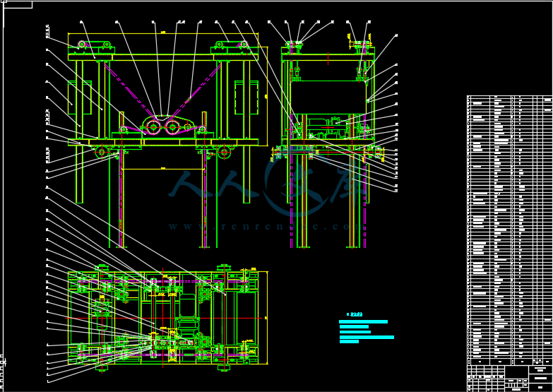
升降采用滚子链,使其运动准确,避免打滑现象,同时利用四个导向柱,增加设备的稳定性。滚子链由大小链轮带动,共四组,布于四周,通过摆线针轮减速机通过齿轮箱带动两根轴实现同步上升。最后在车架两端加上配重,通过钢丝绳与夹盘机构连接,这样可以减轻滚子链受力,减小功率。行走机构通过另一摆线针轮减速机带动行走轴实现行走。
2.2 机构方案的确定
设计方案见图1
图1
3 运动与动力参数的计算
3.1 机构传动简图
图2
1.行走轮 2.行走轴 3.行走摆线针轮减速机 4.行走从动齿轮
5.行走主动齿轮 6.小链轮轴 7.小链轮 8.大链轮 9.升降轴
10.升降从动齿轮 11.升降摆线针轮减速机 12.升降主动齿轮
3.2 减速器及电机的选择
本设计选用B系列摆线针轮减速机,因为摆线针轮减速机具有高速比和高效率。单级传动,就能达到1:87的减速比,效率在90%以上,结构紧凑体积小。运转平稳噪声低,使用可靠、经久耐用寿命长,设计合理,维修方便。B系列摆线针轮减速机减速机适用于24小时连续作制,并允许正反向运转。
型号的表示方法:
图3
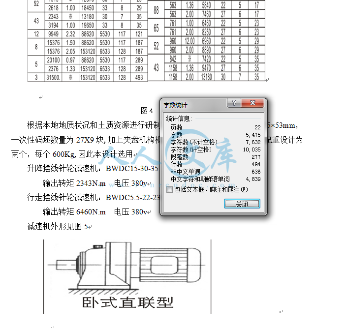
B系列摆线针轮减速机选型表见图4
图4
根据本地地质状况和土质资源进行研制,适合于国家标准砖体240×115×53mm,一次性码坯数量为27X9块,加上夹盘机构框架总重量约1.5t总重约2.4t。配重设计为两个,每个600Kg,因此本设计选用
升降摆线针轮减速机:BWDC15-30-35 输出转速43r/min
输出转矩2343N.m 电压380v
行走摆线针轮减速机:BWDC5.5-22-23 输出转速65r/min
输出转矩6460N.m 电压380v
减速机外形见图5


 川公网安备: 51019002004831号