滚压机设计影响喂料系统的压应力.doc

螺旋管状面筋机总体及坯片导出装置设计【优秀食品加工机械设计含34张CAD图纸】

收藏

资源目录
跳过导航链接。
螺旋管状面筋机总体及坯片导出装置设计【优秀食品加工机械设计含34张CAD图纸】.rar
选题申报表.doc---(点击预览)
说 明 书.doc---(点击预览)
滚压机设计影响喂料系统的压应力.doc---(点击预览)
正式封面.doc---(点击预览)
摘要.doc---(点击预览)
开题报告.doc---(点击预览)
实习报告.doc---(点击预览)
任务书.doc---(点击预览)
文献资料
A0坯片导出及切断部装图.dwg
A2中空轴.dwg
A2大料斗.dwg
A2底版.dwg
A2机架.dwg
A3下料口09.dwg
A3中空轴.dwg
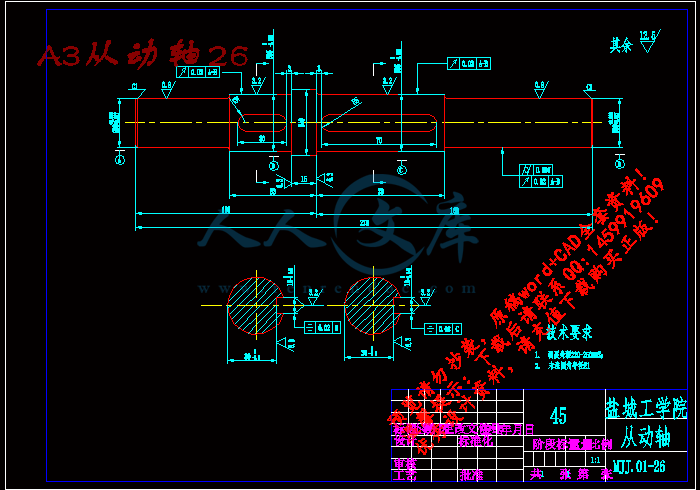
A3从动轴26.dwg
A3从动链轮13.dwg
A3从动链轮28.dwg
A3传动主轴04.dwg
A3传动链轮01.dwg
A3传动链轮03.dwg
A3凸轮切料25.dwg
A3凸轮活塞27.dwg
A3压料板16.dwg
A3导向装置20.dwg
A3小料斗08.dwg
A3推杆22.dwg
A3推杆31.dwg
A3机架05.dwg
A3螺杆11.dwg
A4凸台23.dwg
A4切料刀具18.dwg
A4导向轴套21.dwg
A4挡圈06.dwg
A4挡圈15.dwg
A4活塞32.dwg
A4螺栓销轴19.dwg
A4轴套02.dwg
A4轴套14.dwg
A4轴套24.dwg
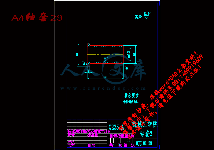
A4轴套29.dwg
A4闷盖07.dwg
压缩包内文档预览:(预览前20页/共24页)
预览图 预览图 预览图 预览图 预览图 预览图 预览图 预览图 预览图 预览图 预览图 预览图 预览图 预览图 预览图 预览图 预览图 预览图 预览图 预览图
编号:480782    类型:共享资源    大小:7.20MB    格式:RAR    上传时间:2015-10-17 上传人:QQ14****9609 IP属地:陕西
45
积分
关 键 词:
螺旋管状 面筋机 整体 导出装置 机械设计 食品加工 机械设计 螺旋管状面筋机总体及坯片导出装置设计
资源描述:

螺旋管状面筋机总体及坯片导出装置设计

螺旋管状面筋机总体设计全套课程毕业设计

螺旋管状面筋机坯片导出装置设计

螺旋管状面筋机总体及坯片导出装置设计【优秀食品加工机械设计含34张CAD图纸】

【带任务书+开题报告+实习报告+申报表+外文翻译】【30页@正文12800字】【详情如下】【需要咨询购买全套设计请加QQ1459919609】

A0坯片导出及切断部装图.dwg

A2中空轴.dwg

A2大料斗.dwg

A2底版.dwg

A2机架.dwg

A3下料口09.dwg

A3中空轴.dwg

A3从动轴26.dwg

A3从动链轮13.dwg

A3从动链轮28.dwg

A3传动主轴04.dwg

A3传动链轮01.dwg

A3传动链轮03.dwg

A3凸轮切料25.dwg

A3凸轮活塞27.dwg

A3压料板16.dwg

A3导向装置20.dwg

A3小料斗08.dwg

A3推杆22.dwg

A3推杆31.dwg

A3机架05.dwg

A3螺杆11.dwg

A4凸台23.dwg

A4切料刀具18.dwg

A4导向轴套21.dwg

A4挡圈06.dwg

A4挡圈15.dwg

A4活塞32.dwg

A4螺栓销轴19.dwg

A4轴套02.dwg

A4轴套14.dwg

A4轴套24.dwg

A4轴套29.dwg

A4闷盖07.dwg

任务书.doc

实习报告.doc

开题报告.doc

摘要.doc

文献资料

正式封面.doc

滚压机设计影响喂料系统的压应力.doc

说 明 书.doc

选题申报表.doc

任务书

课题:     螺旋管状面筋机总体及坯片导出装置设计  

一、设计内容

现行面筋手工成形,手须长期与盐水接触,现设计螺旋管状面筋机,要求成

形到蒸煮期间卷绕尾端不松脱。主要内容有:

1  总体方案设计

1)面筋坯料成型特性研究分析;

2)坯片导出方案设计;

3)坯片切断装置及与卷绕装置的同步设计;

4)卷绕方案设计, 卷绕时螺旋管状的形成方案,上料与下料同步。

2. 结构设计:

1)坯片导出装置设计;

2)坯片切断装置设计;

3.试验样机制作及检测试验。

4.图样设计:坯片导出装置、切断装置部装图及全部零件图。

二、设计依据

1.课题来源:院级科研课题 ;

2.产品名称:螺旋管状面筋机;

3.加工能力:600个/h,单重:125~160g/个;

4.面筋成形要求:螺旋管状面筋,长160~200mm,成形到蒸煮期间卷绕尾端

不松脱。

三、设计要求

1.总体方案设计应有两种以上方案比较和选择;

2.充分考虑面筋粘弹性及随时间、温度变化的特性,对样机试验、总结,改进

设计;

3.坯片形成,导入卷绕机构卷绕,切断坯片,卷绕成形后夹持筷离位,下一夹

持筷上位,坯片再导入,各动作应和谐协调;

4.面筋卷制在盐水环境中工作,既要防止机器锈蚀,又要防止润滑失效或渗入

面筋工作腔;

5.设计图样总量:折合成A0幅面在4张以上;

工具要求:应用计算机软件绘图;

过程要求:装配图需提供手工草图;

6.毕业设计说明书按照学校规定的格式规范统一编排、打印,字数不少于1万

字;

7.查阅文献资料10篇以上,并有不少于3000汉字的外文资料翻译;

8.到相关单位进行毕业实习,撰写不少于3000字实习报告;

9.撰写开题报告。

四、毕业设计物化成果的具体内容及要求

1、设计成果要求:

1)毕业设计说明书                              1   份

2)螺旋管状面筋机坯片导出装置部装图和零件图    1   套

3)螺旋管状面筋机坯片切断装置部装图和零件图    1   套

2、外文资料翻译(英译中)要求

1)外文翻译材料中文字不少于3000字;

2)内容必须与毕业设计课题相关;

3)所选外文资料应是近10年的文章,并标明文章出处。

五、 毕业设计(论文)进度计划

起讫日期工作内容备    注

3月17日~3月18日布置任务

3月19日~4月1日调查研究,毕业实习

4月2日~4月15日方案论证,总体设计

4月16日~4月30日技术设计(部件设计)

5月8日~5月23日工作设计(零件设计)

5月24日~6月7日撰写毕业设计说明书

6月8日~6月10日毕业设计预答辩

6月11日~6月18日修改资料

6月19日~6月21日评阅材料

6月22日~6月24日毕业答辩

6月25日~6月28日材料整理装袋

六、 主要参考文献:

1.辰工.高蛋白“素肉”——面筋[J].中国保健营养,2002,(04):34-35.

2.丁玉庭,邹礼根,陈艳,殷亚峰. 非水法面筋提取的研究[J]. 中国保健营

养,2003,(04):96-97.

3.杨铭铎.面筋形成机理的解析[J].中国烹饪研究,1991,(1):17-20.

4.孟慧英.简单的面筋品质测定法[J]. 粮油仓储科技通讯,2000,(6):20-21.

5.叶伟昌.机械工程及自动化简明设计手册[M].北京:机械工业出版社,2001.

6.李益民.机械制造工艺设计简明手册[M].北京:机械工业出版社,1993.

7.沈世德.机械原理[M].北京:北京机械工业出版社,2001,12.

8.李云.机械制造工艺及设备设计指导手册[M].北京:机械工业出版社,1996.

9. 徐灏.机械设计手册[M].北京:机械工业出版社,2002.

10.胡家秀.机械零件设计实用手册[M].北京:机械工业出版社,1999,10.

螺旋管状面筋机总体及坯片导出装置设计

摘  要:本设计是应楼王淀粉厂的要求而进行设计的,由于目前面筋的生产过程全部为手工作业,工作环境十分恶劣,然而面筋的市场需求量很大(由于其营养价值和市场地位高),所以面筋的机械化操作显得尤为迫切。面筋机的设计分为三个部分:面筋机的坯片导出和切断装置的设计和卷绕装置的设计。本课题为螺旋管状面筋机总体及坯片导出装置设计,着重设计面筋机的坯片导出及切断装置。由于面筋特有的粘弹性质,以及参照去年设计的面筋机样机,在此重新提出的解决方案为:一定量的面筋通过螺旋丝杠的挤压从大料斗被送至小料斗,中间通过切料刀具切断,以便控制单个面筋的重量。被切断的面筋通过导出口导出,被送至卷绕装置卷绕。面筋由于要先切断后通过小料斗导出,所以采用凸轮机构来控制比较方便。采用一大一小两个料斗是更利于面筋的导出成型。这样的设计符合工厂的实际生产需要,满足食品生产的卫生要求,有很高的市场经济的价值。

关键词:面筋;成型机;螺旋管状;坯片导出

The Design of The Overall and The Piece Educing Setting Unit of The Spiral Tubular Gluten Machine

Abstract :The design is requested by Louwang starch factory. The operation of the mechanization of the gluten is especially impendency because the production of the gluten is handiwork at present, the work circumstance is very abominable, and the gluten’s demanding is massive (because of the nutritional value and the market niche). The design of gluten molding machine divided into three parts: the piece educing setting unit, the cutting setting unit and the winding device unit. This project is the design of the overall and the piece educing setting unit of the spiral tubular Gluten machine. It mainly introduce the design the piece educing setting unit and the cutting setting unit because of its unique viscoelastic nature, and the reference to the last design of the gluten molding machine. The solution of the design of the gluten molding  machine: The certain amount of gluten is sent from the big hopper to the small hopper through the helical screw extrusion. The gluten is cut by the middle cutting tool materials. The weight of the single gluten is controled by the cutting tool materials. The gluten which is cut is educed by the export of gluten guidance .The device is sent to the winding device unit. Because the gluten should be cut before it is sent to the export of gluten guidance through the small hopper, the use of cam mechanism to control is more convenient. The  two hoper is more conducive to the gluten derived molding. The design accords with the practical production need of the factory and meets the sanitation demand of the food production .So the design of the gluten shaping machine has a high market economic value.

Key words:gluten; shaping machine; spiral  tubular; piece educing

目    录

1 前言1

2 面筋机系统整体设计2

2.1 总体方案论证2

3 面筋机坯片导出及切断部分具体设计说明4

3.1 进出料口形状设计4

3.2电动机及减速机选择6

3.3电磁离合器选择.6

3.4联轴器选择7

3.5链轮设计及校核   7

3.5.1链轮的设计.7

3.5.2链轮较核8

3.6凸轮设计9

3.7轴设计与主要轴的校核10

3.7.1传动轴的尺寸设计10

3.7.2中空轴的尺寸设计   13

3.7.3从动轴的尺寸设计.14

3.7.4传动主轴较核15

3.8滑动丝杠副选择计算16

3.9轴承及轴承座选取16

3.9.1轴承的选取16

3.9.2轴承的安装方法   17

3.9.3轴承的预紧.17

3.10弹簧的设计计算及校核.17

3.10.1弹簧的设计17

3.10.2弹簧疲劳强度验算   21

4 强度校核22

4.1螺栓校核22

4.2键校核22

4.3销校核23

5 结论24

参考文献25

致    谢26

附    录27

1 前  言

文明的发展和进步可以说与小麦的历史连在一起。早在有历史记载前,人类就种植小麦。1948年,芝加哥大学的考古学家证明小麦的种植起源于中东土壤肥沃的新月形地带。小麦是谷物中最重要的,世界上靠小麦作为食品的人多于靠其它任何食品生活的人。世界上70%以上的可耕地种植粮食,小麦占地最多,高于22%。一年中每个月,世界上都有一个地区收获小麦[1]。

小麦面筋除了在食品行业应用广泛外,在其它行业的应用亦得到蓬勃发展,如医用胶囊;发胶等化妆品;香烟的过滤嘴;鱼虾的饲料;可降解可重新利用的绿色粘贴剂;水泥制造中亦可加入面筋,因为其与Ca交联而增强了水泥的粘合性和防水性;环境保护工作者可将其作为处理废水的固化物[2]。

参 考 文 献

[1]  辰工.高蛋白“素肉”——面筋[J].中国保健营养,2002,(04):34-35

[2]  丁玉庭,皱礼根,陈艳,殷亚峰.非水法面筋提取的研究[J].中国保健营养,2003,

(04):96-97.

[3]  杨铭铎.面筋形成机理的解析[J].中国烹饪研究,1991,(01):17-20.

[4]  李瑜,王兰,尹春明,李艳军.小麦面筋蛋白的磷酸化改性研究[J]. 郑州工程学

院学报,2002,(02):49-64.

[5]  刘冬儿.小麦粉面筋出率的影响因素[J].西部粮油科技,1999,(24):34-35.

[6]  吴晓寅.小麦面筋含量检测方法的探讨[J].粮汕仓储科技讯,2004,(01):52-53.

[7]  黄瑾.小麦面筋与面粉面筋的经验测算方法[J].山东农机,2002.(03):23-24.

[8]  叶伟昌.机械工程及自动化简明设计手册[M].北京:机械工业出版社,2001.

[9]  李益民.机械制造工艺设计简明手册[M].北京:机械工业出版社,1993.

[10] 沈世德.机械原理[M].北京:北京机械工业出版社,2001,12.

[11] 李云.机械制造工艺及设备设计指导手册[M].北京:机械工业出版社,1996.

[12] 机械加工技术手册编写组.机械加工技术手册[M].北京:北京出版社,1989,09.

[13] 胡家秀.机械零件设计实用手册[M].北京:机械工业出版社,1999,10.

[14] 徐灏.机械设计手册[M].北京:机械工业出版社,2002.

[15] 成大先.机械设计手册[M].北京:化学工业出版社,1991,09.


内容简介:
外文翻译 专 业 过程装备与控制工程 学 生 姓 名 杨丽丽 班 级 B 装备 031 班 学 号 0310140118 指 导 教 师 咸 斌 . nts 1 滚压机设计 影响喂料系统的压应力 P. Guigon 杨丽丽 译(有 删节) 摘要 在文章的第一部分,叙述了滚压机的主要特点。 然后 ,讲述了喂料和挤压质量之间的关系。 对于某个静态差距 (无负载 ) ,滚压机的处理量是由螺旋喂料速度决定的 ,与滚筒的速度快慢和需要压实的生产材料无关。当处理量是多种多样的时候,控制差距是一个获得相同质量压坯的好方法。对强烈环节紧凑的应力分布的解释和说明,这些应力是分布在由一根周期旋转的螺杆喂料的滚压机上的。 关键词 :辊压; 喂 料 装置; 压坯异质; 差距控制 1 引言 由于 滚压机 简单、低营运成本的 理念 , 而且 用材广泛, 所以 被用在了许多不同的行业 (化工、 制药、 食品加工、采矿、矿产、冶金 )上 。 广泛 的垃圾回收或处理 就是一个 新兴的应用领域。滚压机的挤压要比第一眼看上去的复杂。 对很多参数和对滚压机理的缺乏了解导致 了滚压机没有 产品的 优越性 。 这篇文章将讲述滚压机的主要部分。 文中 将注意力集中在了解喂料装置是如何影响压实质量的。 2. 滚压机的概说 1-5 滚压机的滚压是一个连续的过程。 功能原理很简单 :料粉是通过重力方式或者通过一根连接两个方向相反正在旋转的辊子的螺杆喂入。 由材料和滚筒表面产生的摩擦在辊子之间的狭小空间里带出料粉,在这些空隙里粉末产生的强大 应力导致了其结构紧凑。 如果滚筒是平滑的或者是槽型的,物料被压紧成致密片 而口袋卷筒将形成煤球型的 (如图 1 所示 )。 nts 2 图 1:滚压机中的压块和压坯 2.1. 压实机制 辊子之间的空间,一般分为三区,在这三个区由不同的机制作用。喂料区:在这个区颗粒的整理应力很小而且致密性很纯粹; 压实区:在这个区挤压力作用明显;挤压区:颗粒开始塑性变形和 /或被压碎。在喂料区和压实区之间的角度是钝角或者是锐角。 图 2:由压电传感器测量的应力分布 2.2. 典型应力 辊子间隙间的压应力的正常分布如图 2 所示。在喂料区当滚筒 作用在粉末上的压力很小时 (小于 0.1 兆帕 ), 它不能用压电传感器测量。 只有压实区的应力才可以用它测量。 应力扩增在小于直角的情况下发生。 应力增加至最大值,这个最大值相当于到达中性角度。 在许多情况下,角度的改变不和辊子间隙成比例,是因为材料覆盖在滚筒的表面。 直角之后,压坯被排出。 弹出物对应的压力急剧下降。 nts 3 2.3.滚压机所具有的优缺点: 滚压机滚压物料有以下几个优点: (1)允许连续运行和有多功能的高生产能力 :适合重工业每小时几百吨的生产 (矿产、肥料 等 )。 (2)压实成本低。 带动滚筒和螺杆运 转的能量是有限的。通常,干燥这一步是不需要的。 (3)需要压实的热材料的气温高达 1000摄示度是可能的。 然而,这项技术目前还有一些弊端: 压坯的外形和尺寸 比冲模挤压出来的不规则。料粉的泄漏 也 要重点解决 。未压碎的料粉 也需要 再挤压。使用真空除尘系统可以大大减少 (可降百分之几 )细粉的泄漏2。 图 3:滚压机的结构 2.4.技术 无论制造商是谁,滚压机的原理都是一样的 ,而且 滚压机 都有相似的结构配置。 市场上卖的滚压机的辊子有水平放置的,有垂直放置的,有倾斜放置的, (如图 3 所示 )。两种不同的结构设 计 要 根据滚压机放置位置的合理性来选择最优的设计 方案 。 在悬臂轴设计中,棍子是被置于框体外面的(如图 3所示)。 这种设计通常被用于小型机器;这样的设计便于辊子的维修。 比较大型的机器用中间轴的设计结构,这就意味着,轴的两端是由铰链连接轴承旋转的,而且辊子是位于框体里面的。制造商对nts 4 A、 B、 C三种结构的优点持有不同的意见。一般来说,一个辊子的轴承在机体里的作用是固定不变的,然而其他可移动的辊子的轴承是靠水压力调节的 2.5.滚动和挤压系统 辊子选择的 方法 一般有两种 :几何特征 (光滑、槽、 和容器设计 )和表面硬度。 对于压块,容器造型的优先使用,这是为了减少排除物的问题和挤压造成的破坏:作用于压坯上的最大允许压力很大程度上取决于辊子的直径。 越大的压力被用于越大的机器上。 辊子的驱动组件必须 保证两根轴间有一个恒定的转距和一个相等的速度,这是为了阻止辊子 较早的 被 磨损坏和破坏压坯的剪应力的形成。为了防止压块,两个辊子间的旋转速度必须一样。一般来说 ,液压系统是用来维持滚动轴承座的 . 采用这种系统,应用力的调整范围可以更广泛。 2.6.喂料系统及隔离 喂料系统是一个好的挤压过程的关键。它必须完成一个统一的连续的物料流动,这是 为了恰当而充 分 的填满辊子间的量从而使压坯形成不均匀质。 该喂料系统还用于密封和除尘装置。 两种不同类型的喂料系统主要是依靠流动特性和粉末的密度来区分使用的。致密性需要制作压坯 有 足够的质量保证:重力的自由向下喂料和强迫喂料 (粉末是被一个或几个螺杆推向辊子的 )。 2.7.粉末的除尘 粉末中的空气有两种逃走的方法 :通过料粉的轴中心,来到喂料装置处;通过辊子之间的空隙和面夹板。 一些空气可以在棍子内被压缩, 这是一个限制生产量和压实质量的关键因素 2。 在压实区使用真空除尘可以有效的优化辊压质量和减小未 挤压的粉末的泄漏。 3. 在实验室滚压机中喂料和压实相互关系的阐述 3.1.实验室滚压机 实验室进行实验的过程如图示 4 所示。 滚压机配备了垂直安装的 130 毫米直径50毫米宽的圆盘。滚压机的详细描述和须知将在 3-6给出。 nts 5 图 4:实验室的滚压机:( 1)辊子( 2)轴承座( 3)辊轴( 4)水平支撑系统( 5)螺旋喂料( 6)搅拌器( 7)喂料漏斗( 8)金属夹( a)压电变换器( b)移动变换器 3.2. 滚压机的吞吐量 对于细粉而言,滚压机的 进料 量是由两个因素限制的。一方面, 进料 量是由细粉的除尘能力限制的。而另一方面, 压实速度又是由颗粒的弹性度限制的。一般来说,当达到临界流量时压实的质量比较差。在这种情况下,要么是由压实引起的风流影响了喂料(除尘能力差),要么是压实的速度太快。这项研究的所有实验都将在低于这个临界流量时进行。因此,当出现细粉压实没有产生带钢或者带钢的质量差的问题时,不是由除尘能力差或滚压速度过高(挤压时间短)引起的。 3.3.挤压率好的挤压场合 挤压速度和螺杆转速的范围大可在实验室滚压机中得到解决。因此,我们研究了在挤压带钢成形中滚压速度和螺杆速度对它的影响。为了清楚地发觉高低滚压速度的限制对挤压成形的影 响我们使螺杆速度固定选择它的挤压速度。在滚压速度低时将发过度挤压,而在滚压速度高时将不形成带钢。 三个操作条件规定如下: 当喂料不足时,由螺旋喂料提供的大量粉末的操作滚压率会太小。在这种情况下,不能挤压微粒物质。 当喂料过多时,由螺旋喂料提供的大量粉末的操作滚压率会太大。滚 子 与滚 子 之间 空隙的 增大 是很重要的。在 喂料过多的 情况下,挤压出来的物质质量会差而且 未 挤压的粉末的 流 失 也很 严重。 好的挤压率是在处于喂料不足和喂料过多之间的挤压率。当挤压材料时产生的带nts 6 钢具有足够的凝聚力和力学强度时,才会有好的挤压率。 图 5:不同辊子对应不同旋转速度的压坯的输出 图 6:辊子的不同速度对应不同的旋转速度而且物料的输出依靠旋转速度而不是和辊速成正比 当螺杆转速固定时,滚压吞吐量是由多种能够形成好的挤压的滚压速度衡量的(如图 5 所示)。对于固定的旋转速度,滚压机的吞吐量也是个常数。在图 6 中,吞吐量是由多种滚压速度下的旋转速度决定的。这个吞吐量要比螺杆单独作用时的吞吐量小。由滚动产生的压力改变了粉末在螺杆内的滑动状态。 3.4. 轧辊辊缝的变化 如果上布的轧辊能纵向移动,当传动力是恒定时轧辊的缝就能从初值增加到一个恒定值。恒定值 是轧辊作用在压实材料上的平均压应力的作用。它也是辊速度 vr的作用,轧辊的生产量是 QC,材料的压实密度是 Qs,轧辊宽是 L,压实材料的摩擦系数nts 7 是 f3: e=Qc LVr s(1- ) 辊缝测量有许多工作要点(辊速度和螺旋转动速度),国际质量曲已给出 (如 图 7所示 )。 图 7:辊子和螺杆的速度之间的标准间隙差距,初次间隙是 0.8mm 3.6. 应力的波动与镭的不同成分的关系如表 6 紧凑的密度分布的特点是通过衡量一个氯化钠晶体的传递分布 。 适当的压力能使氯化钠晶体支离破碎 。 因此 , 同样 的 氯化钠晶体 不是到处 都能传递光的 。 因为氯化钠的透光性能是与局部紧凑地方的压力有关 的 。 承受较少压力的地方因此出现暗色 (如 图 11 所示 )。 机械性能良好可以作为获得紧凑性的特点 , 例如粉碎被使用过的氯化钠 (硼粉 74 时 )。 施加在物料 上的压力既不 符合 辊宽度也不符合时间常数 。 期刊的分布不均 。 周期现象就是螺旋反馈线的周期 。 事实上 , 施加在滚轴间隙上的压力分布与 喂料 系统 压力的分布 有关。 喂料 系统的 压力 有 来自螺旋馈线 的 。 喂料压力的不均匀是由于最后螺旋的螺杆的传动力不均匀 。 nts 8 图 11:氯化钠的透光性(氯化钠 d50, Am74),上图 氯化钠照片的标准灰色度,下图 4. 结论 喂料和压缩特性之间相互作用得到了证明 。 因为使用螺旋给料器,大的压应力产生了 , 并 被 当作滚动和转动的作用 力 。 压力的 大小 仅由螺杆 给料器决定 ,和生产 材料 以及棍子的转速都没有关系 。 结果表明差距曲线可以近似 于 国际质量曲线 。 因此 ,当压力的量不同时 , 控制差距是一个好方法 ,可以用这种方法来 获得相同的压应力。对墙的观测表明 , 颗粒运动喂料区不是连续的 。 螺杆自转 的应力 周期得到了证明 。 从单螺杆喂料的应力分布 看,如果 它们有相同周期 就可以 被观察到。 nts 9 Roll press design influence of force feed systems on compaction P. Guigon *, O. Simon1 Universite de Technologie de Compiegne, BP 20529, 60205 Compiegne cedex, France Abstract In the first part of the article, the main features of roll compactor design are reviewed. Then, the interaction between feeder and compact quality is demonstrated. For a given static gap (no load), the throughput of the press is only a function of the screw feeder speed no matter of the roller speed as long as compacted material is produced. Control of the gap is a good way to obtain compacts of the same quality when throughput is varied. The strong link of the stress distribution of the compact issued from a roll press fed by a single screw with the periodicity of the screw was demonstrated and explained. Keywords: Roll compactor; Feeding device; Heterogeneity of compact; Gap control 1. Introduction Because of their conceptual simplicity and low operating cost, roll compactors are used in many different industries (chemical, pharmaceutical, food processing, mining, minerals, and metallurgical) for a wide variety of materials. A new emerging application is the vast field of waste recycling or disposal. nts 10 Compaction in a roll press is more complicated than it looks at first sight. Many parameters are involved and a lack of understanding of compaction mechanisms results in products that do not possess the required characteristics. This article will review the main features of roll compactors. Then, attention will be focused on the understanding of how the feeding device influences the quality of compacts. 2. Generality about roll compaction Compaction in a roll press is a continuous process. Functional principle is simple: powder is fed by gravity or by means of a screw through two counter currently rotating rollers. Friction between the material and roller surface brings the powder towards the narrow space between the roll (gap), where the powder is submitted to high stresses leading to the formation of compact. If the rolls are smooth or fluted, material is compacted into dense sheets, whereas pocket rolls will form briquettes (Fig.1). nts 11 P. Guigon, O. Simon / Powder Technology 130 (2003) 41 48 42 Fig. 1. Briquetting and compaction in a roll press 2.1. Compaction mechanisms The space between the rolls is generally divided into three zones, where different mechanisms occur: the feeding zone, where the stresses are small and densification is solely due to rearrangement of particles; the compaction zone, where the pressing forces become effective and the particles deform plastically and/or break; and the extrusion zone. The limit between the feeding and the compaction zone is the gripping angle or nip angle 2.2. Stress profile A typical distribution of the normal stress versus the position in the gap between the rolls (roller angle) is represented in Fig. 2. nts 12 Fig. 2. Stress profile measured by the piezoelectric transducers. As the stress exerted by the rollers on the powder in the feeding area is very small (less than 0.1 MPa), it can not be measured by piezoelectric transducers. Only the stress exerted in the compaction area is observable. The stress augmentation takes place below the nip angle. The stress increases until a maximum which corresponds to the neutral angle. In many cases, the neutral angle does not coincide with the roll gap because the material slips along the roller surface. After the neutral angle, the compact is ejected. The ejection corresponds to a rapid decrease of the stress profile. 2.3. Advantages and drawbacks of roll compaction Agglomeration in roll presses has the following advantages: The process is continuous and allows with multiple units of high production capacities: several hundred tons perhour are suitable for heavy industry (mineral, fertilizers, ). The compaction costs are low. The energy consumption is limited to the power to drive the rolls and the screws. Normally, no drying nts 13 step is necessary. Compaction of hot materials with temperatures up to 1000 is possible. However, this technique presents some drawbacks: Aspect and dimension of compacts made by briquetting are less regular than those produced by die pressing. Powder leakage can be important. It is usually necessary to recycle the uncompacted powder. Use of vacuum desecration systems can greatly reduce (down to few percent) the leakage for very fine powder 2. 2.4. Technology Whatever manufacturer, the roll presses consist of the same elements and have similar configurations. Commercially available roller compactors have rolls mounted in a horizontal, vertical or even inclined position as shown in Fig. 3. Two different frame designs exist which are distinguished by the location of the press rollers with respect to the frame. nts 14 Fig. 3. Configuration of roll presses. In cantilever-shaft designs, the rollers are located outside the frame (Fig. 3). This design is normally used for smaller machines; it allows easy access to the rolls for maintenance tasks. Most larger machines use the mill-shaft frame design. This means, both ends of the two shafts are pivoted by bearings and the rolls are located within the frame. Manufacturers are not unanimous about the advantages of configurations A, B, and C. Generally, bearings of one of the rollers are fixed in relation to the frame,while the bearings of the other movable (floating) roller are maintained by an adjustable hydraulic force. 2.5. Rolls and pressurization system Roll choice is essential in two ways: geometrical characteristics nts 15 (smooth, fluted, and pocket design) and surface hardness. For briquetting, pocket shapes are optimized in order to diminish ejection problems and breakage of compacts: maximum applicable stress on the compact depends greatly on roll diameter. Higher stresses are used on larger machines. Roll drive assembly must ensure a constant torque and an equal velocity of the two roll shafts in order to prevent early wear of the rolls and shearing forces which will fracture the compact. In the case of briquetting, both rolls must rotate with exactly the same speed. Generally, a hydraulic system is used to maintain the bearing blocks of the movable roller. By using such a pressurizing system, the applied force can be adjusted within wide limits. 2.6. Feeding systems and confinement The feeding system is the key to a good compaction process. It must achieve a uniform and continuous flow of material in order to fill the nip between the rollers correctly and sufficiently, so that the formed compacts are not heterogeneous. The feeding systems are also used as densification and desertion devices. Two different types of feeding systems are used depending on the flow properties, the density of the powder, and the densification needed to produce compacts of sufficient quality: nts 16 ( 1) gravity feeder for free flowing particles and force feeder (powder is pushed towards the rolls by one or several screws). 2.7. Powder desecration The air fed with the powder can only escape by two paths: axially through the powder, counter currently to the feed; and through the gap between rolls and cheek plate. Some air can be compressed inside the compact. This is a key factor limiting compaction production throughput and compact quality 2. Use of vacuum desecration before the nip roll region is efficient in optimizing roller compaction and minimizing uncompacted powder leakage. 3. Demonstration of the interaction between feeding and compaction in a laboratory roll press 3.1. Laboratory roll press Experiments were carried out on a laboratory roll press (KomarekR B100QC) shown in Fig. 4. The roll press was equipped with 130-mm diameter and 50-mm wide smooth rolls, which were vertically arranged. Detail description of the roll press and instrumentation is given in Refs. 3 6. nts 17 Fig. 4. The laboratory roll press: (1) roll, (2) bearing block, (3) roll shaft, (4) supporting hydraulic system, (5) screw feeder, (6) paddle mixer, (7) feed hopper, (8) cheek plate. (a) Piezoelectric transducers, (b) displacement transducer. 3.2. Roll press throughput For fine powder, the roll press throughput is principally limited by two factors. On one hand, the throughput is limited by the powder deaeration ability, and on the other hand, the compaction speed is limited by the elasticity of the particles. Generally, a poor quality compaction takes place when a critical throughput is reached. In this case, either the airflow generated by compaction disturbs the feeding (bad deaeration) or the compaction is too fast 1. All experiments in this study were conducted below this critical throughput. Therefore, when no strip of compacted powder was produced or when the strip was of poor quality, the problem was not due to poor deaeration or to a too high roller speed (too short compaction time). nts 18 3.3. Compaction rate, good compaction settings A wide range of roller speeds and screw feeder speeds can be set on the laboratory roll press. Therefore, we investigated the influence of roller speed and screw speed on the formation of a compacted strip. The screw feeder speed was fixed and the roller speed was chosen in order to detect visually the higher and lower limits of roller speed that enabled the compaction. At low roller speeds, overcompaction occurred, and at high roller speeds, no strip was formed. Three operating conditions were defined as follows. The subfeeding, corresponding to the operating rate of the roll press when the amount of powder that is provided by the screw feeder is too small. In this case, the particulate material is not compacted. The over-feeding, which corresponds to the operating rate of the roll press when the amount of powder provided by the screw feeder is too large. The compact is extruded between the rolls and the roll gap increase is important. In this case, the compacted material is of poor quality and the powder loss as noncompacted powder is very important. The good compaction rate is an operating rate between sub- and overfeeding. It corresponds to the production of a strip nts 19 of compacted material that exhibits enough cohesion and mechanical strength. For a fixed screw speed, the roll press throughput was measured for several roller speeds Vr, enabling production of a good compact (Fig. 5). For a constant screw speed Vs, the roll press throughput is constant. In Fig. 6, the throughput is measured as a function of Vs for various Vr. This throughput is smaller than the throughput of the screw alone. The counter pressure created by the rollers modifies the slip between the powder and the screw barrel. Fig. 5. Compactor throughput versus roll speed for different screw speeds. nts 20 Fig. 6. Compactor throughput versus screw speed for different roll speeds and comparison with throughput delivered by the screw when not coupled with the roll. 3.4. Roll gap variation If the upper roll can move vertically, the roll gap increases from its initial value to an equilibrium value when the powder is compacted. This equilibrium value is a function of the mean stress applied by the rolls on the compacted material. It is also a function of the rollers speed Vr, the roll press throughput Qc, the density of the compacted material qs, the rolls width L, and the slip of the compacted material on the roll surface f 3: e=Qc LVr s(1- ) The roll gap was measured for many working points (sets of Vs and Vr), and iso-gap curves were computed (Fig. 7). nts 21 Fig. 7. Calculated iso-gap curves (mm) versus roll and screw speed. Initial gap is 0.8 mm. 3.6. Heterogeneity of compact in relation to the fluctuations of stress 6 Distribution of the compact density was characterized measuring the distribution of light transmitted through a sodium chloride compact. The fragmented sodium chloride crystals are oriented by the applied stress, and therefore, light is not diffused similarly in all directions. For sodium chloride, the light transmission property is linked with the stress that has been applied locally on th
温馨提示:
1: 本站所有资源如无特殊说明,都需要本地电脑安装OFFICE2007和PDF阅读器。图纸软件为CAD,CAXA,PROE,UG,SolidWorks等.压缩文件请下载最新的WinRAR软件解压。
2: 本站的文档不包含任何第三方提供的附件图纸等,如果需要附件,请联系上传者。文件的所有权益归上传用户所有。
3.本站RAR压缩包中若带图纸,网页内容里面会有图纸预览,若没有图纸预览就没有图纸。
4. 未经权益所有人同意不得将文件中的内容挪作商业或盈利用途。
5. 人人文库网仅提供信息存储空间,仅对用户上传内容的表现方式做保护处理,对用户上传分享的文档内容本身不做任何修改或编辑,并不能对任何下载内容负责。
6. 下载文件中如有侵权或不适当内容,请与我们联系,我们立即纠正。
7. 本站不保证下载资源的准确性、安全性和完整性, 同时也不承担用户因使用这些下载资源对自己和他人造成任何形式的伤害或损失。
提示  人人文库网所有资源均是用户自行上传分享,仅供网友学习交流,未经上传用户书面授权,请勿作他用。
关于本文
本文标题:螺旋管状面筋机总体及坯片导出装置设计【优秀食品加工机械设计含34张CAD图纸】
链接地址:https://www.renrendoc.com/p-480782.html

官方联系方式

2:不支持迅雷下载,请使用浏览器下载   
3:不支持QQ浏览器下载,请用其他浏览器   
4:下载后的文档和图纸-无水印   
5:文档经过压缩,下载后原文更清晰   
关于我们 - 网站声明 - 网站地图 - 资源地图 - 友情链接 - 网站客服 - 联系我们

网站客服QQ:2881952447     

copyright@ 2020-2025  renrendoc.com 人人文库版权所有   联系电话:400-852-1180

备案号:蜀ICP备2022000484号-2       经营许可证: 川B2-20220663       公网安备川公网安备: 51019002004831号

本站为文档C2C交易模式,即用户上传的文档直接被用户下载,本站只是中间服务平台,本站所有文档下载所得的收益归上传人(含作者)所有。人人文库网仅提供信息存储空间,仅对用户上传内容的表现方式做保护处理,对上载内容本身不做任何修改或编辑。若文档所含内容侵犯了您的版权或隐私,请立即通知人人文库网,我们立即给予删除!