目录.doc

半轴的机械加工工艺及钻6-Φ14孔、车削外圆顶尖夹具设计【优秀带两套夹具设计含11张CAD图纸】

收藏

资源目录
跳过导航链接。
压缩包内文档预览:
预览图 预览图
编号:481435    类型:共享资源    大小:880.84KB    格式:RAR    上传时间:2015-10-24 上传人:QQ14****9609 IP属地:陕西
40
积分
关 键 词:
机械加工 加工工艺 车削 夹具设计 半轴的机械加工工艺及钻6-Φ14孔、车削外圆顶尖夹具设计
资源描述:

半轴机械加工工艺及工装设计全套课程毕业设计

半轴的机械加工工艺及钻6-Φ14孔夹具设计

半轴的机械加工工艺及车削外圆顶尖夹具设计

半轴的机械加工工艺及钻6-Φ14孔、车削外圆顶尖夹具设计【优秀带两件套夹具设计含11张CAD图纸】

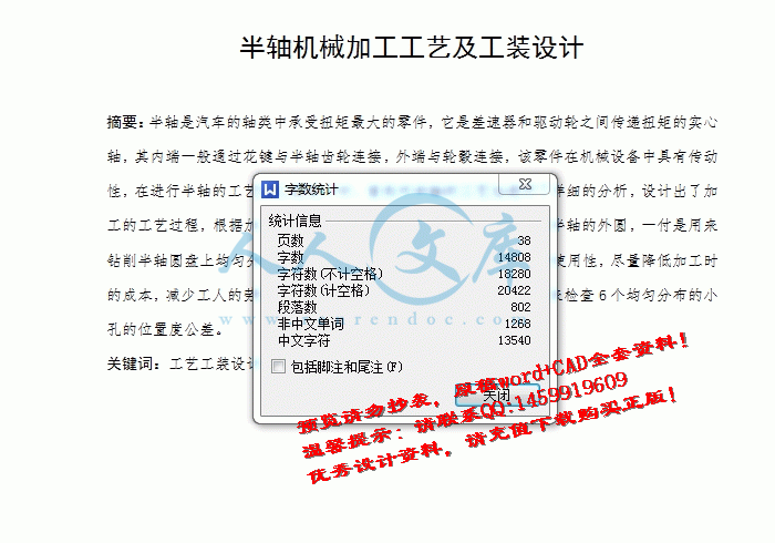
【带任务书+开题报告+工艺过程工序卡片+外文翻译】【38页@正文14800字】【详情如下】【需要咨询购买全套设计请加QQ1459919609】

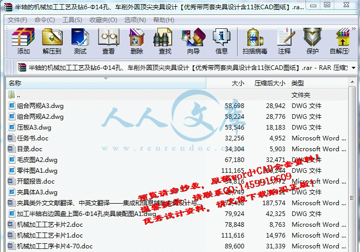
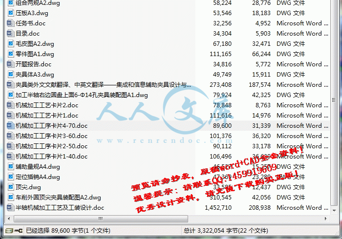
任务书.doc

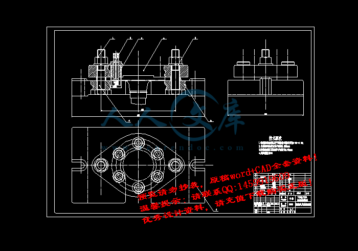
加工半轴右边圆盘上面6-Φ14孔夹具装配图A1.dwg

半轴机械加工工艺及工装设计.doc

压板A3.dwg

夹具体A3.dwg

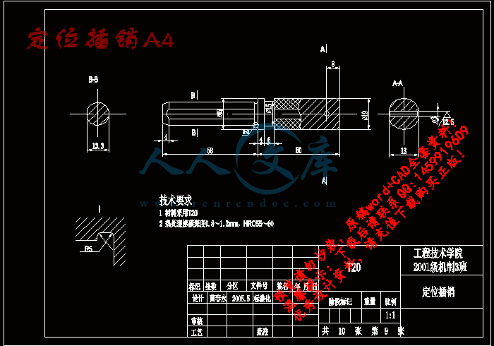
定位插销A4.dwg

开题报告.doc

机械加工工序卡片1-40.doc

机械加工工序卡片2-50.doc

机械加工工序卡片3-60.doc

机械加工工序卡片4-70.doc

机械加工工艺卡片1.doc

机械加工工艺卡片2.doc

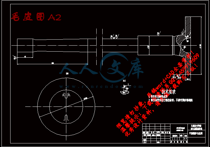
毛皮图A2.dwg

目录.doc

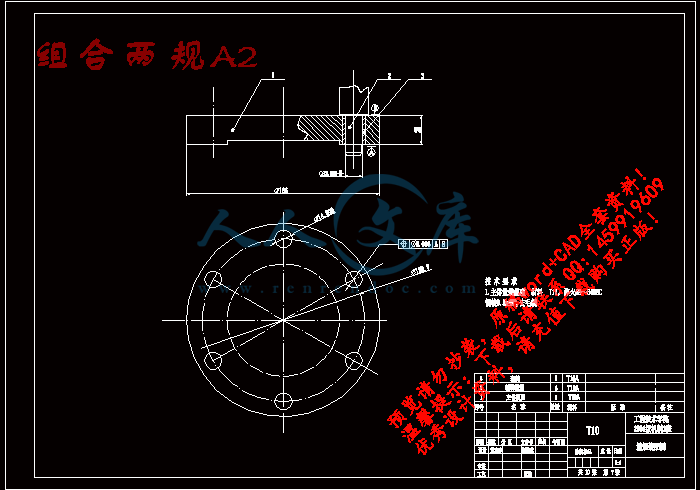
组合两规A2.dwg

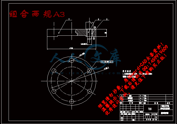
组合两规A3.dwg

车削外圆顶尖夹具装配图A2.dwg

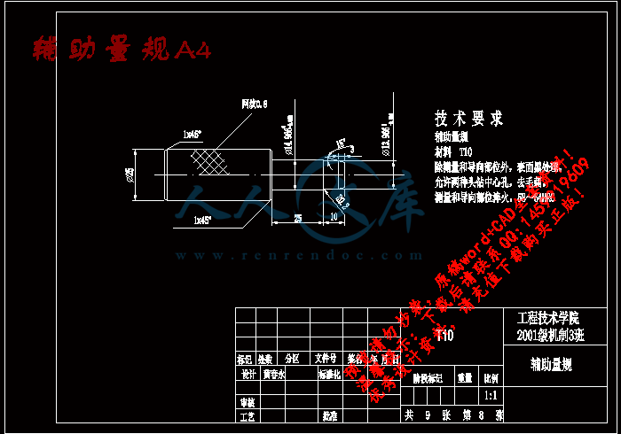
辅助量规A4.dwg

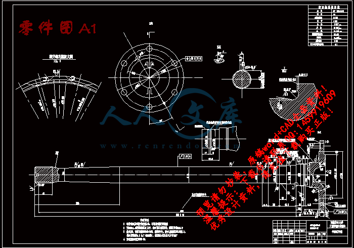
零件图A1.dwg

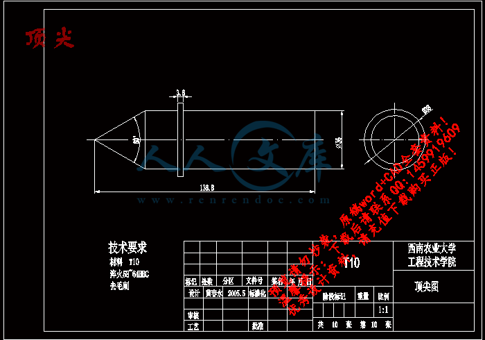
顶尖.dwg


任务书

论文题目半轴机械加工工艺及工装设计

毕业设计(论文)目的、要求:

1、培养综合运用所学理论知识,独立分析和解决工程技术问题的能力。培养学生创新能力。

2、培养收集、查阅、分析各种文献资料的能力。进一步提高计算、绘图等技能。

3、学会使用工具书籍,通过夹具设计,提高结构设计能力。

4、初步掌握机械制造工艺规程设计和夹具设计的基本要求和设计方法;掌握设计计算说明书的编写。

毕业设计(论文)主要内容:

1、绘制零件图1张;设计夹具2付,绘制夹具图;设计专用组合量具1付。(一部分图纸必须用计算机绘制)。

2、设计机械加工工艺规程(生产纲领按成批生产)。

3、填写工艺过程卡1份。设计4~5道工序的详细工序卡。

4、图纸总量折合A0号2~3张;

5、文献综述(3000字以上);

6、设计计算说明书(1.5万字以上)和中英文说明书摘要。

7、英译汉(3000字以上)。

半轴机械加工工艺及工装设计

摘要:半轴是汽车的轴类中承受扭矩最大的零件,它是差速器和驱动轮之间传递扭矩的实心轴,其内端一般通过花键与半轴齿轮连接,外端与轮毂连接,该零件在机械设备中具有传动性,在进行半轴的工艺和工装设计时,首先对半轴的工艺性进行了详细的分析,设计出了加工的工艺过程,根据加工要求设计专用夹具设计,一付是用来车削半轴的外圆,一付是用来钻削半轴圆盘上均匀分布的小孔,在设计中注意的夹具的经济性和使用性,尽量降低加工时的成本,减少工人的劳动强度,除此还进行了组合量具的设计,用来检查6个均匀分布的小孔的位置度公差。

关键词:工艺工装设计   夹具设计    组合量具设计

Abstract:The half stalk is in automotive stalk the acceptance twist the biggest spare parts of sqire , it is bad soon machine and drive the round of delivers to twist the  of solid stalk, it inside carry generally pass to spend the key and half stalk wheel gears to connect, carry outside with a conjunction, that spare parts is in the machine equipments have to spread to move sex, at carry on the half stalk of craft and work equip to account, the half axial craft carried on the detailed analysis first, designing processed craft process, according to process to request to design the appropriation tongs design, a pay is to use to come to car to pare the outside circle of the half stalk, on pay is use to drill to pare a dish of the half stalk up even distribute of eyelet, in the design the economy of the advertent tongs and usage, as far as possible lower to process of cost, reduce the worker of labor strength, in addition to this still carried on the design that the combination quantity have, use to check 6 even distribute of a business trip of position of the eyelet.

Key Words:The craft work packs the design   The tongs design    Combine the quantity has the design

目 录

摘要……………………………………………………………………………………1

英文摘要………………………………………………………………………………1

文献综述………………………………………………………………………………2

1  引言………………………………………………………………………………6

2  零件分析…………………………………………………………………………6

2.1零件的生产纲领及生产类型………………………………………………6

2.2零件的作用…………………………………………………………………6

2.3零件的工艺分析……………………………………………………………6

3  工艺规程制造的形式……………………………………………………………7

3.1确定毛坯制造形式…………………………………………………………7

3.2定位基准的选择……………………………………………………………7

3.2.1粗基准的选择………………………………………………………7

3.2.2精基准的选择………………………………………………………7

3.3零件表面加工方法的选择…………………………………………………7

3.4制订工艺路线………………………………………………………………8

3.5机械加工余量及毛坯尺寸的确定………………………………………9

4  选择加工设备……………………………………………………………………12

4.1 选择机床…………………………………………………………………12

4.2选择夹具…………………………………………………………………12

4.3选择刀具…………………………………………………………………12

4.4选用量具…………………………………………………………………12

5  确定切削用量和基本时间………………………………………………………13

5.1 工序00铣削用量及基本时间的确定…………………………………13

5.2 工序10切削用量及基本时间的确定……………………………………14

5.3 工序30切削用量及基本时间的确定……………………………………19

5.4 工序40铣削用量及基本时间的确定……………………………………21

5.5 工序50削用量及基本时间的确定………………………………………22

5.6 工序60钻削与垂直轴线的的孔………………………………………24

5.7 工序70攻螺纹M6…………………………………………………………26

5.8 工序110磨削外圆表面及左端面………………………………………26

6夹具设计…………………………………………………………………………27

6.1 车削顶尖夹具的设计……………………………………………………27

6.2 绘制夹具总体图…………………………………………………………29

6.3 钻孔专用夹具的设计……………………………………………………29

6.4 绘制夹具总体图…………………………………………………………31

7位置量规设计 ……………………………………………………………………31

小结…………………………………………………………………………………33

参考文献……………………………………………………………………………34

致谢…………………………………………………………………………………35

文献综述

夹具设计综述

一  前言

在机械制造中,为完成需要的加工工序、装配工序及检验工序等,使用着大量的夹具。利用夹具,可以提高劳动生产率,提高加工精度,减少废品;可以扩大机床的工艺范围,改善操作的劳动条件。因此,夹具是机械制造中的一项重要的工艺装备。按夹具的应用范围分类有:通用夹具、专用夹具、成组夹具、组合夹具;按夹具上的动力源分类有:手动夹具、气动夹具、液压夹具、电动夹具、磁力夹具、真空夹具、切削力及离心力夹具 。

(一)夹具设计的基础理论

一个好的机床夹具,首先要保证能加工出合格的产品。为此,所设计的夹具首先应满足以下两项要求:

(1)在未受外力作用时,加工件对刀具和机床应保持正确的位置,即加工件应有正确的定位。(2)在加工过程中,作用于加工件上的各种外力,不应当破坏加工件原有的正确定位即对加工件应有正确的夹紧。

(二)定位原理

在机械加工中,我们要求加工出来的表面.对加工件的其它表面保持规定的位置尺寸。因为加工表面是由切削刀具和机床的综合运动所造成,所以在加工时,必须使加工件上的规定表面(线、点)对刀具和机床保持正确的位置才能加工出合格的产品。

⑴ 定位原理

把加工件上的规定表面(线、点)与夹具上的规定表面(线、点)相互靠住的这一措施,叫做夹工件在夹具中的定位。该加工件上的这种规定表面(线、点)称为定位基准。

参考文献

[1] 王启平.机床夹具设计[M].哈尔滨:哈尔滨工业大学出版社,1996.1~134,207~249.

报,2000(12):105~108.

[2].艾兴.肖诗纲.切削用量简明手册[M],机械工业出版社,2000年3月。

[3] Subramanian V,Kumar Senthil A.Seow K C .A multi agent approach to fixture design.Journal of Intelligent Manufacturing,2001,12(1):31~42.

[4] 机械制造工艺设计手册简明手册[M]。哈尔滨:哈尔滨工业大学出版社。

[5] 东北重型机械学院.洛阳工学院等 机床夹具设计手册[M].上海科学技术出版社,

[6] 吴宗泽.罗国华.机械设计课程设计手册[M],1992.3~1999.6.

[7] 闫志中,刘先梅.计算机辅助夹具设计方法及发展趋势[J].内蒙古林学院学报,

1996,18(3):69~74.

[8] 王凤岐,许红静,郭伟.计算机辅助夹具设计综述[J].航空制造技术,2003(11):38~40.

[9] 朱耀祥,融亦呜.夹具设计自动化的现状及发展趋势[J].机械科技,1993(10):14~17.

[10] 张福润,徐鸿本,刘延林.机械制造技术基础[M].武昌:华中科技大学出版社,2000.288~320.

[11] 赵家齐.机械制造工艺学课程设计指导书[M].北京:机械工业出版社,1997.60~61.

[12] 顾崇衔等.机械制造工艺学[M].西安:陕西科学技术出版社,1990.4~58.

[13] 徐志刚.基于广义映射原理的组合夹具结构设计自动化[J].机械工程学

[14] 王小华.机床夹具图册[M].北京:机械工业出版社,1992.36~37,40~41.

[15] 丁殿忠,姜鸿维.金属工艺学课程设计[M].北京:机械工业出版社,1997.6~14.

[16] 王启义机械制造装备设计[M] 冶金工业出版社  

[17] 王凤岐.许红静.航天制制造技术[J].天津大学出版社, 2003(11).-38-40

[18] 李青. 机械工程与自动化[J]. 004(6).-99-101,103

[18] Liao Jianmin. Fixturing analysis for stability consideration in an automated fixture design system.Journal of Manufacturing Science and Engineering,2002,124(2):98~104.
内容简介:
西南农业大学本科 毕业 论文 ( 设计 )任务书 论文题目 半轴机械加工工艺及工装设计 专业名称 班级 下达 日期 学 号 姓名 指导教师 毕业设计(论文)目的、要求: 1、培养综合运用所学理论知识,独立分析和解决工程技术问题的能力。培养学生创新能力。 2、培养收集、查阅、分析各种文献资料的能力。进一步提高计算、绘图等技能。 3、学会使用工具书籍,通过夹具设计,提高结构设计能力。 4、初步掌握机械制造工艺规程设计和夹具设计的基本要求和设计方法;掌握设计计算说明书的编写 。 毕业设计(论文) 主要内容: 1、 绘制零件图 1 张;设计夹具 2 付,绘制夹具图;设计专用组合量具 1 付。(一部分图纸必须用计算机绘制)。 2、 设计机械加工工艺规程(生产纲领按成批生产)。 3、 填写工艺过程卡 1 份。设计 4 5 道工序的详细工序卡。 4、 图纸总量折合 A0号 2 3 张; 5、 文献综述( 3000 字以上); 6、 设计计算说明书( 1.5 万字以上)和中英文说明书摘要。 7、 英译汉( 3000 字以上)。 指导教师签名: 2004 年 12 月 10 日 说明: 1.此表由指导教师完成。原则上用计算机打印( A4 纸),可在各学院教学办拷贝表格或从教务处网页下载;若用钢笔填写,必须做到字迹工整、清晰。 2.请将毕业设计(论文)任务书装订在毕业设计(论文)的第一页 。 ntsntsntsntsntsntsntsntsntsntsntsntsntsntsntsntsntsntsntsntsntsntsntsntsntsntsntsntsntsntsntsntsntsntsntsntsnts 附录 附录 1:外文翻译 集成 和 信息 辅助 夹具设计与制造 F. MERVYN, A. SENTHIL KUMAR* and A. Y. C NEE 虽然大量的研究已 应用于 开发计算机辅助夹具设计系统, 但 夹具设计制造领域和其他领域 之间的信息交换并 没有彻底处理。本文针对这一差距 , 在夹具设计中 通过 应用 适当的信息模 型 研究 计算机辅助夹具设计系统和集成支持制造业。 夹具设计的模型 主要是 介绍有关 夹具设计, 以及 其他设计和制造活动。 对应用 在XML 的信息模型和信息交流 中的 一个基于 XML 的消息传递模型的方法进行了讨论 。 关键词: 夹具设 计,综合设计和制造 ;信息建模 ; 1.介绍 在一个旨在降低产品交货时间和成本以及提高产品质量 的过程中 ,企业寻求各种工程所涉及的一体化进程设计和制造产品。适当的整合将允许在一个产品实现涉及领域作出的决定 适用于 其他领域的需要,导致整体的最优解设计和制造产品。计算机辅助系统发挥了关键作用 在于 协助不同领域开展工作。开发集成设计和制造系统的 一个 关键成功因素在于能在各种电脑辅助系统的信息 进行 交流。夹具设计领域的发展已出现大量的电脑辅助系统 的应用 。在制造过程设备服务于持有目的工件和保持一个安全方面的一致关系的工具。已通过各 种办法发展半自动化,自动化夹具设计系统。张毕( 2001)努力提出的这些 最新成果 。尽管 通过 大量的研究, 适应各 域之间的信息和其他制造业领域 的 交流 ,但是 需求并没有得到彻底处理。适当的夹具设计信息模型描述知识和技术规格将有助于大大提高产品质量和缩短产品交货时间。本文的目的是要为解决通过对相应的信息化辅助模式的夹具设计系统, 并 支持集成设计和制造。该这项工作的范围只限于加工装置 本文组织如下:第 2 条的有关研究进行讨论在发展生产的信息模型 ;第 3 条提出了一个活动模型夹具设计 ;第 4 给出了不同的夹具设计信息模式,以支持集成设计 和制造,而第 5 条提出了一个使用 XML 的例子,实现了信息模型。 第 6 节介绍交流信息的夹具设计方法为基础上的信息模型和第 7 条最后的文件。 2.相关研究 nts 制造业的信息交流的重要性已经 发展了 发展各种信息模型为代表的加工过程。国际标准化组织 10303 部分(国际标准化组织, 1997)是一个应用协议的存储和交换(美联社)进程之间的数控加工零件计划的资料不同的计算机辅助工艺规划( CAPP 系统)系统。对 AP 213 的范围包括规划信息的数控加工计划,生产任务的指示利用数控机床的一部分,数控编程和过程检验资料。 Wysk 等。 ( 1995年)制定了工艺方案和正式代表模式联营工厂资源模型。他们的工作范围是就如何处理计划可以用在车间控制环境,从而提供整合工艺规划和生产之间的执行。性等。 ( 1998)开发了一个信息模型的 CAPP 系统 。 采用面向对象的建模和偏微分方程 发展 数据技术。该模型包括零件信息模型,计划信息模型的过程和生产资源信息模型。该工艺方案模型包含制造业活动的资料,例如程序,设置和制造业务。在制造工程工具包( METK)项目,标准和技术研究所( NIST)的在美国开发的一个过程计划(李 1999 年)作为信息模型在整合过程中的规划和 NC 验证的应用程序的手段 , 这个过程计划规定对每个产品的流程顺序指示。 Ryou 和 Jerard( 2001)最近开发的基于 XML 的一个代表性数值称为控制标记语言( NCML 之)作为一个有利的技术,允许买家和自定义加工零件卖方通过互联网进行电子商贸。在代表性,资料工件,设置,工具和信息宽容是提供让用户判断一个零件的可制造。很明显从文献回顾,信息的加工过程发展模式要么不提供或只提供信息装置固定装置的信息作为车间执行系统资源。原因这是因为在集成设计和制造设备的作用已被忽视,不经过深入的探讨。 通过 模式的发展,活动模型通常是 先发展。活动模式设置在其中的 作用 是不同的域之间的交换方面设计和制造,从而确定捕获的信息类型在信息模型。这些活动的模型的一些审查中可以找到( 1996)。活动模式发展至今,装置只能被视为一个制造系统的资源。对装置的影响一个产品的设计仍没有得到处理。在确定一个产品 的 关键作用,准确度也高,一个制造系统的灵活性 、 夹具的能力,有效的产品,因此应在设计关注一个产品。本文针对这在当前制造业信息化差距模型提出一个模型,夹具设计活动的需要考虑作用在产品设计和制造设备。适当的夹具设计信息模型,然后发展到支持集成的设计和制造业。该 信息模型的开发利用作为一个 XML 的文件格式和交换信息的基础上的做法。 3.夹具设计活动模型 拟议的夹具设计活动的模型如图 1 所示。 该活动已使用 IDEF0 方法描述,并且只有在一个描述抽象的层面,使信息模型是独立的执行这些活动的。在图 1 可以看出,一为综合设计夹具设计系统与制造执行两个主要活动,格 A1 -夹具概念设计和 A2 -详细夹具设计。 夹具设计活动的概念是一个规划过程的一部分活动,在那里他们讨论了需要nts概念工艺规划的活动,支持产品设计的概念确定生产过程,选择资源和设备,从制造成本估算的概念活动输出发送反馈到产 品概念设计活动。作为活动的一部分概念工艺规划,通过对活动支持的困难分析概念产品设计夹具设计的概念夹具在该产品的特点,估计该产品的加工成本所采取的固定装置和夹具的制造时间。到投入活动是概念产品设计,产品的数量的估计是生产和当前夹具清单。该任务的概念夹具设计活动有: 1.确定要使用夹具的类型为基础的估计量该产品被制造。 2.在加工过程中的部分限制的基础上确定的困难概念产品的几何形状。 3.估计的时间和新设备的设计和制造成本如果目前的库存设备不能使用。 夹具的概念设计活动的 关键 是信息模型 和 概念设计 的 反馈。这 将提供产品信息模型与问题反馈设计,并提供了夹具上一个度量产品设计人员比较关注的不同的初始设计。 图 1.夹具设计活动模型。 夹具的概念设计活动的输出是信息模型 与 概念设计反馈。这将提供产品信息模型 与 问题 的 反馈设计,并提供了一个度量产品设计人员比较关注的夹具上有不同的初始设计。 该夹具的详细设计活动的投入是固定的类型从概念夹具设计活动的信息,中间部分模型将被加工和夹具库存信息。中间部分模型零件的几何 关系 设置。作为一个例子,图 2 显示了一个部分,需要 3 设置机器的特点。中间部分是固定式模式,在每个安装图 中显示。中间部分模型可以得出一旦制造业序列测定。应当指出,该夹具设计活动作为输入接收 信息控制 整个零件模型。该 图 提供了对现有夹具元件所需资料,以便夹具设计中使用。 nts 图 2.例如部分,中间部分的模型。 夹具的详细设计活动的任务是: 1.设计为每个安装夹具。这包括进行夹具布局夹具的设计和配置设计。 2.评估所设计的夹具以及如何履行其职能的准确定位,限制和支持工件 3. 生成的铺地板的固定装置处理必要的指示。这包括在夹紧工件和正确的到达的每 个夹紧力应驱动。顺序夹具的详细设计活动的输出是信息模型,中间部分模型反馈,夹具配置和组装工件装载指示。 中间部分模型提供反馈信息反馈的过程以及如何规划师每个零件模型之间的中间可以设置固定式。反馈将使这个进程规划 达到 夹具最佳工艺方案。 夹具装配模型的配置信息有两个目的。首先,它提供有关的信息工具的夹具装配路径规划配置。这些信息可以被用来生成夹具装配的检查刀具路径之间的干扰和夹具元件。其次,它使车间人员构建基于组件的夹具提供信息。 工件装载指示信息模型提供车间工件如何 适用于 于人员的指示和 信号 灯。 4.夹具设计信 息模型 本节描述了各种夹具设计信息模型的细节将要生成的夹具设计活动。该信息模型已使用 XML 实现。两种方法可以用来表示数据时使用 XML,第一是使用一个文档类型定义( DTD),第二个是使用一个 XML 架构。在这项工作中,我们代表的数据使用一个 DTD。一个 DTD 定义该元素可以出现在一个 XML 文件和办法,使他们能够出现。对每个 DTD 的结构信息模型解释了部分。这些文件是由一个开发计算机辅助夹具设计产生系统(默文等 , 2003)。 nts4.1 概念设计 和 反馈 该概念设计反馈 XML 文件的 DTD 列于 图 3 是由四个组的信息了: (一)产品设计的评价是进行了身份, (二)固定式的使用, (三)该概念设计的几何评价,并 (四)预计成本和时间,制造灯具。 图 3.概念设计反馈 DTD 的 XML 文件。 在该夹具类型的基础上加以确定的估计量产品被生产。该夹具类型要么是 专用 或 弹性 。一般来说,一个专一个灵活的夹具用于小批量的生产。用夹具用于大批量的生产和几何直观的评价应该是对产品设计人员认识上的夹具设计产品的几何效应。有关资料也应可解释为电脑自动化环境中使用。为了要做到这一点,几何评 价已经被映射到该产品的特点设计。每个产品的功能,被加工有三个属性, 定位 ,克制 和 支持 。这些属性是一个代表的职责夹具。因此,他们描述的能力,夹具加工过程中的一部分功能。虽然有几个功能可以在一次装夹加工,这个映射已经被采纳,使产品设计师能够轻松地认识到这一问题的该产品的几何形状。三个属性的每个有两个子属性, 存在人脸 和 脸 获取。这两个属性的集体描述能否完成特定功能的灯具。面对存在的属性指的是寻找缓解面临的定位,夹紧工件和支持在加工的功能。此属性将一个整数的数值范围从 1 至 5,1 个非常容易和非常困难的 5。辅助功能属性的脸指的是在公司目前的库存夹具能够访问夹具的脸。这可能是一两个值, 标准 或 特殊 。如果脸难以进入,一个可能需要特殊的夹具和值将是 特殊 。标准装置是可以买现成的,现成的或现有的装置元素在可用于装夹部分用于公司。这个属性允许产品设计人员了解有关产品的成本影响几何夹具及采取的制造夹具的时间。例如,如果类型的夹具 是nts一个灵活的夹具,但面临的无障碍特殊,它意味着由于该产品几何,专用夹具需要一个灵活的,虽然夹具的基础上更适合需要的产品数量。这将使产品设计师,了解了产品的增加导致时间和成本。 在成本和 时间估算属性有三个子属性,估计费用制造夹具,预计需时多久制造的,可以在一夹具加工工件夹具蔚,数量。这些属性使产品设计师 1 夹具的成本和效果的估计的夹具在产品交货时间。总体而言,这一信息模型提供了难易程度反馈夹具概念设计。该 fixturability 据分析映射以该产品的模型功能允许直观地了解产品设计师其特点将构成装夹加工过程中的问题。产品设计人员可以使用这些信息来作出评估的概念设计或改变之间关于 fixturability 关注的几个概念设计。 4.2 中间部分模型 fixturability 反馈 该模型的中间 部分的 XML 文件的 DTD fixturability 反馈需要的 结构如图 4 所示。 图 4.中间部分模型 fixturability 反馈 DTD 的 XML 文件 。 在这个信息模型中,模型的中间部分评价是基于三个属性, 定位 , 克制 和 支持 。如前面提到的,这些属性是一个固定的职能的代表。不过,相对的概念产品设计评价,中间部分模型的详细信息可在这个阶段。因此,在履行职能的能力上更彻底的代表性在此提供的信息模型。对位置属性的孔来定位和信息的一部分建立一个基准误差估计。每个定位孔上有定位元素限制。基准误差 估计属性从工件位置的理想位置提供的信息可能偏差。这一信息是提供 6 个自由度,翻译nts从 X -, y 轴和 z 轴和旋转攻方的 X, Y 型和 Z -轴。属性的限制和支持也包含的信息用于工件夹紧和支持。属性的限制有进一步的约束分析属性。此属性描述的能力夹具以制止在加工过程中工件的议案。这可能需要一两个值,限制或无限制。类似属性的约束分析,支持属性具有变形分析子属性。此属性介绍了夹具在机械加工能力,以支持和工件防止变形。此属性将一个整数的值从 1 至 5, 1 对应非常差和 5 对应非常好。基准误差估计,约束分析和变形分析属性提供反馈的进程以及如 何规划每个可以是固定的中间部分模型。 nts附录 2:英文原文 Fixture design information support for integrated design and manufacturing F. MERVYN, A. SENTHIL KUMAR* and A. Y. C NEE Although a vast amount of research has been conducted on developing computer-aided fixture design systems, the need for information exchange between the fixture design domain and other manufacturing domains has not been thoroughly dealt with. This paper addresses this gap in fixture design research through the development of appropriate information models for computer-aided fixture design systems to support integrated design and manufacturing. A fixture design activity model is presented that relates fixture design to other design and manufacturing activities. The implementation of the information models in XML and the exchange of the information models based on an XML messaging approach are also discussed. Keywords: Fixture design; Integrated design and manufacturing; Information modelling; XML 1. Introduction In an aim to reduce product lead-time and cost as well as improve product quality, enterprises seek the integration of the various engineering processes involved in the design and manufacture of a product. Proper integration will allow the different domains involved in the realization of a product to make decisions taking into account the requirements of other domains, resulting in overall optimal solutions for the design and manufacture of a product. Computer-aided systems play a key role today in aiding the different domains carry out their tasks. A crucial factor in the success of developing integrated design and manufacturing systems lies in the ability to exchange information among the various computer-aided systems. The fixture design domain has seen a vast amount of research in developing computer-aided systems. Fixtures are devices that serve the purpose of holding a workpiece securely and maintaining a consistent relationship with respect to the tools during a manufacturing process (Nee et al. 1995). Various approaches have been adopted in developing interactive, semi-automated and automated fixture design systems. Bi and Zhang (2001) present a recent review of these efforts. Despite the vast amount of research, the need for information exchange between the fixture *Corresponding author. Email: mpeask.sg International Journal of Production Research ISSN 00207543 print/ISSN 1366588X online 2006 Taylor & Francis http:/www.tandf.co.uk/journals DOI: 10.1080/00207540500465303 design domain and other manufacturing domains has not been thoroughly dealt with (Mervyn et al. 2003a). Appropriate information models describing fixture design knowledge and specifications could help to significantly improve product quality and reduce product lead-time. The aim of this paper is to take a step towards addressing ntsthis need through the development of appropriate information models for computeraided fixture design systems to support integrated design and manufacturing. The scope of this work is limited to machining fixtures. This paper is organized as follows: section 2 discusses the related research carried out in developing manufacturing information models; section 3 presents an activity model for fixture design; section 4 presents the different fixture design information models to support integrated design and manufacturing, while section 5 presents an example of the information models implemented using XML. Section 6 describes the exchange of the fixture design information models based on a messaging approach and section 7 concludes the paper. 2. Related research The importance of information exchange in manufacturing has seen the development of various information models for representing the machining process. ISO 10303 Part 213 (ISO, 1997) is a STEP application protocol (AP) for storing and exchanging process plan information for numerically controlled machined parts between dissimilar computer-aided process planning (CAPP) systems. The scope of AP 213 includes planning information of NC process plans, task instructions to manufacture a part using NC machines, NC programming and in-process inspection information. Wysk et al. (1995) developed a formal representation schema for process plans and an associated factory resource model. The scope of their work was on how process plans can be used in a shop floor control environment, thus providing integration between process planning and production execution. Xing et al. (1998) developed an information model for CAPP by using object-oriented modelling and the PDES/ STEP data techniques. The model consists of the part information model, the process plan information model and the production resource information model. The process plan model contains information on manufacturing activities such as processes, setups and manufacturing operations. The manufacturing engineering toolkit (METK) project at the National Institute of Standards and Technology (NIST) in the USA developed an information model for a process plan (Lee 1999) as a means of integrating process planning and NC validation applications. The process plan provides instructions on the sequence of processes for each product. Ryou and Jerard (2001) recently developed a representation based on XML called numerical control markup language (NCML) as an enabling technology to permit buyers and sellers of custom machined parts to conduct e-commerce via the Internet. In the representation, information regarding workpiece, setups, tool information and tolerance is provided to allow users to judge the manufacturability of a part. From the literature review, it was evident that the machining process information models developed either do not provide information on fixtures or only provide information on fixtures as a resource for shop floor execution systems. The reason for this is that the role of fixtures in integrated design and manufacturing has been overlooked and not thoroughly explored. In the development of standard 2 F. Mervyn et al. information models, an activity model is normally developed first. Activity models set the context in which information is exchanged between the different domains in ntsdesign and manufacturing, and thus determine the type of information captured in information models. A review of some of these activity models can be found in Feng (1996). In the activity models developed thus far, fixtures have only been considered as a resource for manufacturing systems. The effect of fixtures on the design of a product has not been dealt with. Fixtures play a key role in determining the accuracy of a product and also, the flexibility of a manufacturing system. The ability to effectively fixture a product should therefore be a concern in the design of a product. This paper addresses this gap in current manufacturing information models by presenting a fixture design activity model that takes into account the role of fixtures in product design and manufacturing. Appropriate fixture design information models are then developed to support integrated design and manufacturing. The information models are developed using XML as a file format and exchanged based on a messaging approach. 3. Fixture design activity model The proposed fixture design activity model is as shown in figure 1. The activities have been described using IDEF0 and are only described at an abstract level so that the information models are independent of the implementation of these activities. As seen in figure 1, a fixture design system for integrated design and manufacturing performs two main activities, A1Conceptual Fixture Design and A2Detailed Fixture Design. The conceptual fixture design activity is part of a conceptual process planning activity, described in Feng and Zhang (1999), where they discuss the need for a conceptual process planning activity that supports conceptual product design by determining the manufacturing processes, selecting resources and equipment, and estimating manufacturing costs roughly. The output from the conceptual process Figure 1. Fixture design activity model. planning activity is sent as feedback to the conceptual product design activity. As part of the conceptual process planning activity, the conceptual fixture design activity supports conceptual product design through an analysis of the difficulties in fixturing the product during the machining of the product features, estimation of the cost of the fixtures and the time taken to manufacture the fixture. The inputs to the activity are the conceptual product design, the estimated quantity of the product to be manufactured and the current fixture inventory. The tasks of the conceptual fixture design activity are: . Determine the type of fixture to be used based on the estimated quantity of the product to be manufactured. . Determine difficulties in restraining a part during machining based on the conceptual product geometry. . Estimate the time and cost of designing and manufacturing new fixtures if the current inventory of fixtures cannot be used. The output of the conceptual fixture design activity is the information model, conceptual design fixturability feedback. This information model will provide product ntsdesigners with feedback on fixturability problems and also provides a metric for product designers to compare different initial designs in terms of fixturing concerns. The inputs to the detailed fixture design activity are the type of fixture information from the conceptual fixture design activity, the intermediate part model, the faces of the intermediate part model that will be machined and the fixture inventory information. The intermediate part model is the geometry of the part in between setups. As an example, figure 2 shows a part that requires three setups to machine the features. The intermediate part models to be fixtured at each setup are shown in the figure. The intermediate part model can be derived once the manufacturing sequences are determined. It should be noted that the conceptual fixture design activity receives the entire part model as an input. The fixture Figure 2. Example part and intermediate part models. inventory provides the necessary information on the available fixture elements to be used in fixture design. The tasks of the detailed fixture design activity are: . Design the fixture for each setup. This includes carrying out fixture layout design and fixture configuration design. . Evaluate how well the designed fixture fulfils its functions of accurately locating, restraining and supporting a workpiece. . Generate the necessary instructions for shop floor handling of fixtures. This includes arriving at a proper sequence for clamping the workpiece and the force that each clamp should be actuated with. The outputs of the detailed fixture design activity are the information models, intermediate part model fixturability feedback, fixture assembly configuration and workpiece loading instructions. The intermediate part model fixturability feedback information model provides feedback to the process planner on how well each intermediate part model between setups can be fixtured. The feedback will allow the process planner to arrive at the optimal process plan taking into account fixturing considerations. The fixture assembly configuration information model serves two purposes. Firstly, it provides tool path planners with information on the fixture assembly configuration. This information can then be used to generate the fixture assembly for checking of interference between the tool path and fixture elements. Secondly, it allows shop floor personnel to construct the fixture assemblies based on the provided information. The workpiece loading instructions information model provides shop floor personnel instructions on how the workpiece should be located and restrained on the fixture. 4. Fixture design information models This section describes the details of the various fixture design information models to be generated by the fixture design activities. The information models have been implemented using XML. Two approaches can be used when representing data using ntsXML; the first is to use a document type definition (DTD) and the second is to use an XML schema. In this work, we represent the data using a DTD. A DTD defines the elements that can appear in an XML document and the way in which they can appear. The structure of the DTD of each information model is explained in this section. These files are to be generated by a developed computer-aided fixture design system (Mervyn et al. 2003b). 4.1 Conceptual design fixturability feedback The DTD of the conceptual design fixturability feedback XML file is shown in figure 3 and is made up of four groups of information: (i) the ide
温馨提示:
1: 本站所有资源如无特殊说明,都需要本地电脑安装OFFICE2007和PDF阅读器。图纸软件为CAD,CAXA,PROE,UG,SolidWorks等.压缩文件请下载最新的WinRAR软件解压。
2: 本站的文档不包含任何第三方提供的附件图纸等,如果需要附件,请联系上传者。文件的所有权益归上传用户所有。
3.本站RAR压缩包中若带图纸,网页内容里面会有图纸预览,若没有图纸预览就没有图纸。
4. 未经权益所有人同意不得将文件中的内容挪作商业或盈利用途。
5. 人人文库网仅提供信息存储空间,仅对用户上传内容的表现方式做保护处理,对用户上传分享的文档内容本身不做任何修改或编辑,并不能对任何下载内容负责。
6. 下载文件中如有侵权或不适当内容,请与我们联系,我们立即纠正。
7. 本站不保证下载资源的准确性、安全性和完整性, 同时也不承担用户因使用这些下载资源对自己和他人造成任何形式的伤害或损失。
提示  人人文库网所有资源均是用户自行上传分享,仅供网友学习交流,未经上传用户书面授权,请勿作他用。
关于本文
本文标题:半轴的机械加工工艺及钻6-Φ14孔、车削外圆顶尖夹具设计【优秀带两套夹具设计含11张CAD图纸】
链接地址:https://www.renrendoc.com/p-481435.html

官方联系方式

2:不支持迅雷下载,请使用浏览器下载   
3:不支持QQ浏览器下载,请用其他浏览器   
4:下载后的文档和图纸-无水印   
5:文档经过压缩,下载后原文更清晰   
关于我们 - 网站声明 - 网站地图 - 资源地图 - 友情链接 - 网站客服 - 联系我们

网站客服QQ:2881952447     

copyright@ 2020-2025  renrendoc.com 人人文库版权所有   联系电话:400-852-1180

备案号:蜀ICP备2022000484号-2       经营许可证: 川B2-20220663       公网安备川公网安备: 51019002004831号

本站为文档C2C交易模式,即用户上传的文档直接被用户下载,本站只是中间服务平台,本站所有文档下载所得的收益归上传人(含作者)所有。人人文库网仅提供信息存储空间,仅对用户上传内容的表现方式做保护处理,对上载内容本身不做任何修改或编辑。若文档所含内容侵犯了您的版权或隐私,请立即通知人人文库网,我们立即给予删除!