圆管带式输送机说明书.doc

DG500型圆管带式输送机的设计【优秀新型辅助运输设备机械课程毕业设计含13张CAD图纸】

收藏

资源目录
跳过导航链接。
DG500型圆管带式输送机的设计【优秀新型辅助运输设备机械课程毕业设计含13张CAD图纸】.rar
圆管带式输送机说明书.doc---(点击预览)
南非金矿的刮刀绞盘电机 -他们的失败调查外文文献翻译.docx---(点击预览)
任务书.docx---(点击预览)
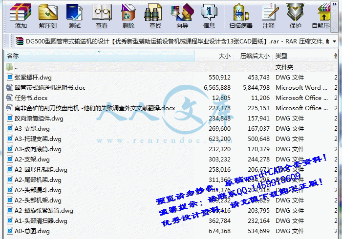
A0-总图.dwg
A1-头部清扫器.dwg
A2-圆形托辊组.dwg
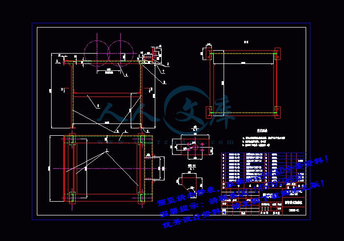
A2-头部机架.dwg
A2-头部漏斗.dwg
A2-尾部机架.dwg
A2-支架.dwg
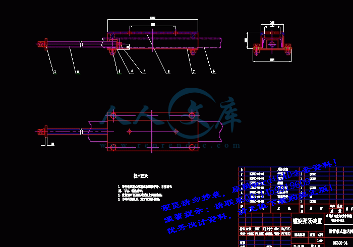
A2-螺旋张紧装置.dwg
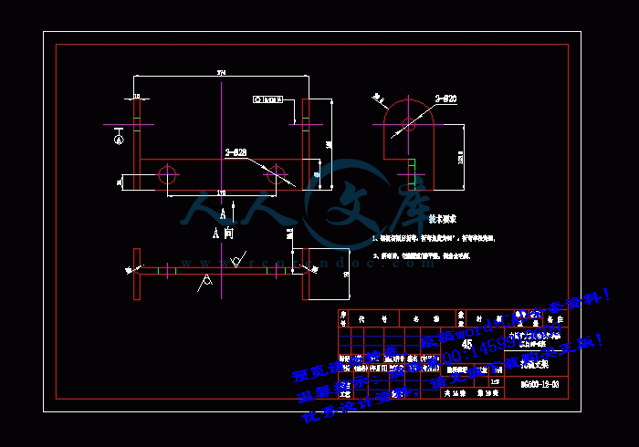
A3-托辊支架.dwg
A3-支腿.dwg
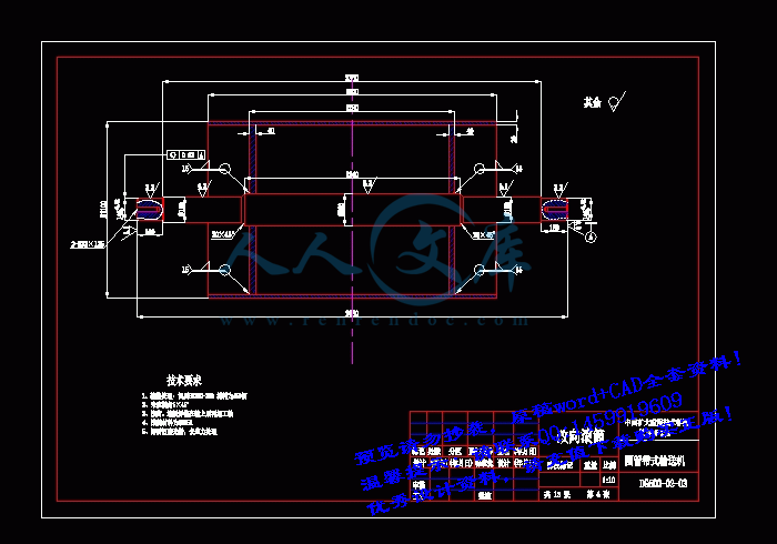
A3-改向滚筒.dwg
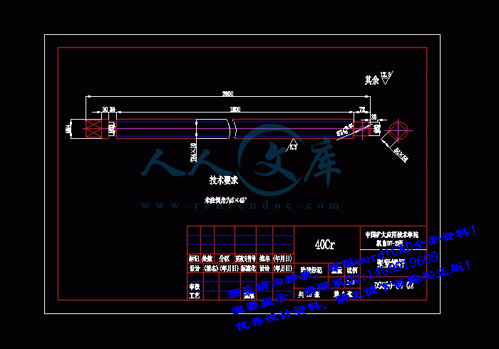
张紧螺杆.dwg
改向滚筒组件.dwg
压缩包内文档预览:(预览前20页/共89页)
预览图 预览图 预览图 预览图 预览图 预览图 预览图 预览图 预览图 预览图 预览图 预览图 预览图 预览图 预览图 预览图 预览图 预览图 预览图 预览图
编号:514882    类型:共享资源    大小:9.17MB    格式:RAR    上传时间:2015-11-12 上传人:QQ14****9609 IP属地:陕西
45
积分
关 键 词:
dg500 圆管 带式输送机 机械设计 新型辅助 运输设备 机械课程毕业设计 DG500型圆管带式输送机的设计 新型辅助运输设备机械课程毕业设计
资源描述:

DG500型圆管带式输送机的设计

新型辅助运输设备机械课程毕业设计

圆管带式输送机的设计

DG500型圆管带式输送机的设计【优秀新型辅助运输设备机械课程毕业设计含13张CAD图纸】

【带任务书+外文翻译】【66页@正文30000字】【详情如下】【需要咨询购买全套设计请加QQ1459919609】

A0-总图.dwg

A1-头部清扫器.dwg

A2-圆形托辊组.dwg

A2-头部机架.dwg

A2-头部漏斗.dwg

A2-尾部机架.dwg

A2-支架.dwg

A2-螺旋张紧装置.dwg

A3-托辊支架.dwg

A3-支腿.dwg

A3-改向滚筒.dwg

任务书.docx

南非金矿的刮刀绞盘电机 -他们的失败调查外文文献翻译.docx

圆管带式输送机说明书.doc

张紧螺杆.dwg

改向滚筒组件.dwg

任务书

毕业设计题目:圆管带式输送机

毕业设计专题题目:

毕业设计主要内容和要求:

1、查阅有关资料、完成圆管带式输送机总体方案的设计;

2、完成驱动装置及总体结构设计;

3、完成电动滚筒设计;

4、机架及主要组件、零件图设计及零件加工工艺编制;

5、编写完成整机设计计算说明书、中英文翻译,包括图表不少于15000字;

6 完成不少于3000字的英译汉翻译;

7 完成机械图纸总量不少于3张0号图纸。

摘  要

DG500型圆管带式输送机是一种新型的辅助运输设备。该型运输机设计的目的主要应用于面粉厂两车间之间面粉的运输,同时也适应于清洁快速的连续短距离输送颗粒性的物品。

DG500型圆管带式输送机主要由电动滚筒、联轴器、改向滚筒、输送带、托辊、机架、拉紧装置、清扫器与给料系统等组成。

该型输送机采用封闭式运输可防止外部杂物混入输送物料,也能防止物料遭受雨淋、日晒,并可实现承载段和回程段完全封闭输送,原理上可以避免漏料、洒料等,可满足环保要求。

DG500型圆管带式输送机在运量上可以完成100t/h,运输量较大,并且采用更换机架的形式可以进行倾斜、垂直、转弯等一系列普通带式运输机所不能完成的运输方式。

该型输送机结构紧凑,结构为近似对称布置;输送距离短,方便移动;运转平稳,安全可靠,安装方便。

关键词:输送机; 封闭运输

ABSTRACT

DG500 pipe belt conveyor is a novel type of auxiliary transport equipment. It is designed to transport flour between the two workshops. Besides, it can be used to transport the clean and fast continuous short-range particles items. DG500 pipe belt conveyor mainly composed of electric drum, couplings, bend pulley, belt, roller, frame, tensioning device, cleaning device and feed system components. The bearing segment and return segment of this type of conveyor is complete closed transport. This characteristics can prevent transportation of materials from external debris. Meanwhile, it can prevent materials from rain and sun. So, in principle, this type of conveyor can avoid leakage, spilled materials, etc, and can meet the environmental requirements. DG500-type pipe belt conveyor transportation volume is large, and can finish the transportation volume of 100t / h, and through replace the rack, it can be used to tilted, vertical, turning transport which is the common mode of transport can not complete. This type of conveyor has the feature of compact in frame, approximately symmetrical arrangement of structure; transmission distance is short, easy movement; smooth running, safe and reliable, and easy installation.Keywords: conveyor; closed transport;

目    录

1概述1

1.1封闭输送带式输送机的分类1

1.1.1 圆管带式输送机1

1.1.2 吊挂带式输送机3

1.1.3 异型截面带式输送机4

1.1.4 各种密闭输送带式输送机的特点对比5

1.2 圆管带式输送机的特点6

1.2.1 优点6

1.2.2 缺点6

1.3 圆管带式输送机的发展7

1.3.1 圆管带式输送机的发展水平7

1.3.2 圆管带式输送机的理论研究8

1.4 圆管带式输送机的组成9

1.5 本文主要的工作9

2 圆管带式输送机的总体设计10

2.1 主体结构10

2.2  机架组合形式12

2.3 输送带13

2.3.1输送带类型13

2.3.2 成圆方式15

2.3.3密封方式16

2.3.4放置方式16

2.4 托辊17

2.5  机架18

2.6  附加部件18

2.7  驱动装置20

2.8  启动系统20

3 圆管带式输送机的总体计算21

3.1 设计的条件21

3.2 输送机横截面积A,带速v和管径D的计算21

3.3 输送机功率的估算22

3.4 张力计算23

3.4.1 有效张力计算23

3.4.2 最大张力计算24

3.5 成圆损失24

3.6 输送带下垂度24

3.7 输送带层数25

3.8 验算托辊载荷26

4 输送带的选择与设计28

4.1  输送带分类与结构28

4.1.1 输送带的分类28

4.1.2 输送带结构29

4.1.3 带芯30

4.1.4  编织方法对强度的影响31

4.1.5 圆管式输送带技术规格31

4.2 输送带宽度及滚筒直径的计算31

4.2.1 输送带宽度计算31

4.2.1 滚筒直径的计算32

4.3 输送带工作张力32

4.3.1最大工作张力32

4.3.2 输送带的安全系数33

4.3.3 额定拉断力33

4.3.4 输送带疲劳强度安全系数33

5 托辊的设计与选择35

5.1 托辊的选择35

5.1.1 缓冲托辊35

5.1.2 成圆托辊35

5.1.3 圆形托辊36

5.1.4 辊子载荷计算38

5.2 托辊轴承39

5.2.1轴承的选定与安装39

5.2.2 轴承的寿命40

5.2.3轴承的拆卸与清洗41

6 滚筒的设计与选择42

6.1 滚筒分类和形式42

6.1.1 按驱动方式分类42

6.1.2 按轴承内孔大小分类42

6.1.3 按外形区分42

6.1.4 按功能区分43

6.2 滚筒规格43

6.2.1 传动滚筒基本直径和长度43

6.2.2 改向滚筒外形尺寸44

6.3 滚筒的轴45

6.3.1 轴设计的程序46

6.3.2 轴的强度计算46

6.4 电动滚筒47

6.4.1 电动滚筒的作用47

6.4.2 电动滚筒功率计算48

6.4.3 电动滚筒转矩计算48

7 输送机的线路及机架的设计50

7.1 线路设计50

7.2 成圆段设计50

7.2.1 成圆段的长度50

7.2.2 过渡段托辊的布置52

7.3 机架的设计52

7.3.1 带式输送机布置准则52

7.3.2 圆管带式输送机机架设计53

8 给料系统、拉紧装置与清扫器的设计54

8.1 给料系统54

8.1.1 给料机的分类54

8.1.2 给料机的特点54

8.2拉紧装置55

8.2.1 拉紧装置的功能55

8.2.2拉紧装置的分类56

8.3 清扫器56

9 总结59

1概述

随着现代化发展的要求,环保成为当今时代一个日趋重要的问题,在世界范围内引起广泛关注。输送系统在工作中产生的粉尘和撒料,对环境污染已经引起世界各国输送机设计、制造和使用部门以及行政管理部门越来越多的关注。为了减少输送过程的污染,提倡环保无害化输送物料,从而导致人们对封闭输送的开发和研究。

封闭输送带式输送机是以特殊的机械结构,通过输送带的围包将散状物料包裹在输送带的内部进行输送。封闭输送带式输送机在某种程度上具有管道输送的特点,但是在宏观上物料和输送带没有相对运动,而是被输送带包裹着随输送带一起运行来完成物料的输送任务。

对该机种的研究与开发是从20世纪70年代开始,至今已经出现了多种形式的封闭型带式输送机,其基本形式有圆管带式,吊挂式,和其他异型管式(指断面形状而言)带式输送机等。

参考文献

[1] 成大先. 机械设计手册(第四版,第一卷).北京:化学工业出版社,2002

[2] 成大先. 机械设计手册(第四版,第二卷).北京:化学工业出版社,2002

[3] 成大先. 机械设计手册(第四版,第三卷).北京:化学工业出版社,2002

[4] 成大先. 机械设计手册(第四版,第四卷).北京:化学工业出版社,2002

[5] 成大先. 机械设计手册(第四版,第五卷).北京:化学工业出版社,2002

[6]张钺.新型圆管带式输送机设计手册.北京.化学工业出版社,2006

[7]张钺.皮带机设计原理和应用.贵阳.史州人民出版社.1980

[8]叶云岳.直线电机技术手册.北京.机械工业出版社.2003

[9]戴光皓.粮食输送机械.郑州:河南出版社.1991

[10]夏炽宁.胶带输送机在电厂应用情况与技术要求,连续输送技术.1991.(3-4):947

[11]美国输送设备制造商协会联合会编.散状物料输送机.北京.机械工业出版社.1985

[12]宋伟尉,张国伟,邓永胜.圆管带式输送机过渡段计算机仿真与设计,东北大学学报(自然科学版).2003, 24

[13]张安宁,李洪久.圆管带式输送机过渡段长度的确定.煤矿机械,1995.(4)115

[14]宋伟刚.带式输送机的动力学模型,连续输送技术.1995.(2).20

[15]徐振渡,付兴承,压带式无倾角带式输送机若干机理探讨.连续输送技术.1988.(2)130

[16]郭永存,张安宁,圆管带式输送机过渡段长度的确定.矿山机械.1995.(2);26

[17]宋伟刚,彭兆行.气垫带式输送机的设计与计算.矿山机械.1994.(6-7-8).43

[18]张钺,法国长距离带式输送机的设计特点.连续输送技术.1990.(1):41

[19]张钺,刘宇琦.国内外圆管带式输送机的新发展.矿山机械.2000.(8)。63

[20]张钺,刘宇琦.中间直线摩擦传动胶带输送机设计原理和应用,连续输送技术.1988,(1-2);17

[21]Horak R.M.  Improved Idler Panel Design for Pipe conveyor.  Bulk Solids Handling,  1997,  (17):S21

[22] Marton A.  E.  Tubular Pipe ConVeyor Design Using a Standard Belt.  Bulk Solids Handling,  2000,  (20):39

[23] Marton A.  E.  Tubular Pipe Convcyor Design A review of cmss selection and belt selection Bulk Solids Handling,


内容简介:
中国矿业大学毕业设计任务书 学院 专业年级 学生姓名 任 务 下 达 日 期 : 20*年 2 月 28 日 毕业设计日期: 20*年 3 月 7 日至 20*年 6 月 10 日 毕业设计题目: 圆管带式输送机 毕业设计专题题目: 毕业设计主要内容和要求: 1、查阅有关资料、完成圆管带式输送机总体方案的设计; 2、完成驱动装置及总体结构设计; 3、完成电动滚筒设计; 4、机架及主要组件、零件图设计及零件加工工艺编制; 5、编写完成整机设计计算说明书、中英文翻译, 包括图表不少于 15000 字; 6 完成不少于 3000 字的英译汉翻译; 7 完成机械图纸总量不少于 3 张 0 号图纸。 院长签字: 指导教师签字: nts 英文原文 SCRAPER WINCH MOTORS ON SOUTH AFRICAN GOLD MINES AN INVESTIGATION INTO THEIR FAILURE JF Pritchard CF Landy Dept. of Electrical Engineering ABSTRACT This paper investigates some of the probable reasons forfailure of squirrel cage induction machnes dnving scraperwinches in South African Gold Mines. The paper shows theresults of load current and voltage unbalance measurements that were recorded on winches in operation. There arefurther measurements showing the presence of time harmonics in the supply to some winches. More importantly,the paper shows the measured torque-speed curve of atypicai scraper winch machine. This curve seems to inhace that there are significant space harmonics present in the air gap of the winches, which may be causing rotor heating and pre-mature bearing failure. INTRODUCTION In South African gold mines, a winch known as a “scraper winch” is used to scrape ore-bearing rock from the rock -face after blasting. The winch consists of a mechanical winch powered by a squirrel cage induction motor. The mostcommon rating for the scraper winch motor is 37kW, 525V,5 1A. It is well known in the SA mining industry that these winches do not last for more than about 4 to 6 months in operation underground before they bum out and have to be sent to the surface for re-winding. A number of theories have been advanced by engineers working on the mines as to why these machines fail so often, however, none of these theories have so far been adequately documented or proven. Scraper winches normally operate in the stopes (the sections where mining operations are on-going) and as such, it is difficult to install and remove them easily since the railway lines underground do not extend all the way into the stopes. Once a winch bums out, it may often take up to 2 to 3 full shifts before a new winch can be installed in its place and as a result, a significant amount of production is lost. If one considers that a large gold mine with more than one active shaft, may have up to 1000 scraper winches in operation at any one time (and these winches are being replaced on average, twice a year), and one factors in the cost of rewinds as well as lost production, it becomes evident that scraper winches are costing the gold mining industry a lot of money every year. This paper highlights some research that has been done at the University of the Witwatersrand to investigate the reasons for failure of scraper winch motors in South African gold mines. The paper describes part of the preliminary investigation that involved researchmg literature on squirrel cage nts induction machine failures as well as the results of visits to machine repair organisations involved with winch motor repairs for the mines. Thereafter, the results of measurements that were taken underground are discussed. Laboratory tests that were camed out on scraper winch motors are also highlighted and the results thereof are discussed. THE PRELIMINARY INVESTIGATION The reasons for squirrel cage induction machine failures are quite well documented in the literature 1,2,3,7. It seems that in meQum voltage, small machmes, the predominant component that fails is the stator winding insulation. Stator failures can often be attributed to electrical supply problems such as voltage unbalance, single phasing, time harmonic voltages in the supply, undervoltage, overvoltage and voltage transients. There are also load factors such as mechanical overloading of the machine, and thermal cycling of the insulation that can lead to thermal as well as mechanical ageing of the insulation. Environmental factors 111 are also often cited as stresses that act on the stator insulation. In particular, voltage tracking (even in med” voltage motors) across the slot insulation due to moisture and dirt finding their way inside the machne is a common reason for failures in machines that operate in “dusty” environments. Clogging of the airways, corrosion of the laminations and deterioration of the insulation due to moisture 1,4 are also sometimes quoted as environmental reasons for failure. Mechanical abrasion of the insulation due to foreign particles entering the machine may also lead to machine failure. DriR-uroof machines During the investigation, a number of failed scraper winch motors were observed at two machine repair organizations. Of these, the majority were enclosed in drip-proof enclosures, while some were housed in totally enclosed, fan cooled enclosures (TEFC enclosures). The drip proof machines were found to all have evidence of rust on the stator cores, with small stones and mine sludge being found in the overhangs of the machines. Large amounts of grease and oil were also found inside most machines, which came either from the bearings, or from the gear-box to whch the machines are attached, or both. In one case a stone of 3cm diameter was found in the overhang. One repairer claimed that he sometimes finds it necessary to press the rotor out of the stator using a machine (once the bearings were of) due to the large number of foreign particles jammed into the air gap. Regarding the drip-proof machines, it became evident hat a major factor leading to failure was abrasion of the stator insulation due to the presence of foreign particles inside the machine. Because of these obvious short-comings associated with drip-proof motors, nts according to one source in the mining industry, most of the mines nowadays purchase only TEFC machines. For this reason, it was decided to neglect drip proof machines in the investigation and focus solely on TEFC machines. TEFC machines Of the failed TEFC machines, it seemed that there was also evidence of rust and sometimes grease inside some of the “sealed machines, however, it was of a lesser extent compared to the drip-proof machines. It seems that the grease found in these machines also worked its way into the sealed housing from the bearings and the adjacent gear-box. The appearance of rust in supposedly “sealed machines is also not dflicult to explain if one considers that when a machine is run, the air inside heats up and expands, hence pressure the seals and some of it may find its way out. When the machine is allowed to cool, the air inside contracts and a partial vacuum is established which may allow moisture-laden air to enter the machine, depending on how well it is sealed. Both machne repairers claimed that when machines come in for repair they sometimes find that an earth fault thatwas noticed when the machine came in initially, is alleviated when the machine is opened up and dried out. Also, it seems that the bearings are almost always in need of replacement and the machine repairers replace the bearings every time asa matter of course. Based on this evidence, it seems that bearing failures and voltage traclung due to moisture may at least be one component leading to TEFC scraper winch failures. pH measurements inside failed machines Some engineers have claimed that scraper winches fail because of non-balanced pH aqueous solutions finding their way onto the stator winding and corroding it. While it is not clear that an acidic or alkali solution does in fact corrode the insulation or the impregnating varnish faster than normal water 4, it was decided to check if this may in fact be one additional factor to consider. A relatively recent paper in a mining journal 5 indicates that fissure water in South African gold mines has a pH value that varies from 2.67 in some areas in the Witwatersrand to 9.77 in the Free State. Furthermore,another paper was found 6 that showed that significant amounts of nitrous fumes are given off during the blasting process whch can combine with water vapour (of which there is an abundance underground) to produce nitrous acid. Since the scraper motors are very near to the blasting area and are always in the presence of water vapour, it seems that dilute acids and alkalis may find their way into scraper machmes in some mines. As a further test, a sample of 10 failed, drip proof machines (since they are more exposed to the environment than TEFC machines) from 2 mines in the Witwatersrand nts were opened up and tested for pH content using colour fixed pH indxator sticks (with a pH accuracy of 1). The procedure was to dip the sticks into distilled water and then press them against the inside of the stator bore in 4 different places. Of all the machines that were tested, not one registered a pH content of other than 7 (balanced), indicating that there was no sigruficant acid or alkali concentration inside the machines. Although this was a rather crude experiment on a very small sample of machines, it does seem to indicate that pH content is not a real factor when looking for reasons for failure of scraper winch motors. UNDERGROUND MEASUREMENT RESULTS In order to assess the quality of the supply to scraper winch motors underground, as well as to assess the loading on the machines, it was decided to log measurements of the three phase line current, voltage and power to a series of machines in operation underground. Coupled with this, it was decided to record spot current waveforms for analysis later. The data was sampled and logged on a portable computer using a 16 bit data acquisition card PAC). The measurement transducers consisted of two wide bandwidth, battery powered current probes and two small voltage transformers. These were connected to a unit housing a high order anti-aliasing filter, which in turn passed the signal to the DAC. The voltage and current on two lines was measured directly using the transducers and the voltage and current on the other 2 phases was inferred using the fact that the voltage and current in a 3 phase, 3 wire system sum to zero. The input power was measured using the standard 2 wattmeter method, using the voltage and current transducers, with the multiplication etc., being done in the software. The software was set up in such a way as to allow the DAC to sample at 15& and acquire batches of 3000 points. This enabled a true RMS reading of all 3 line voltages and currents to be taken roughly every 314 of a second and recorded. The high loggmg frequency was necessary in order to capture machmes running up, as well as rapid load changes which can happen in less than a second. The current waveforms that were captured were also sampled at 15&, with 60000 points being stored. This was done to give a frequency resolution of 0.25Hi in the frequency domain. Due to the physical constraints involved with measuring underground, it was only possible to log data measured at one machine site for three shifts. Unfortunately, the only suitable site for measurement was in an area of the mine where the machines were not being pushed too hard (according to some miners) because of the relatively short haulage path for the winches (for more discussion of the actors affecting loading on the machine, see lo). While the results that were recorded may presumably not be taken to be true of scraper winches in general, they do give what appears to be a good indication of the duty cycle of scraper winches. Figures 1-3 below show the average nts current (i.e. the sum of all three phases divided by 3) that was recorded over 3 shifts of operation. It is clear from the current plots that the scraper winch being observed has a highly irregular duty cycle. It is also clear from the plots that the amount of loading is very irregular. The large current peaks correspond to starting current peaks. The reason some starting peaks are less than others is to do with the fact that the sample batches were not synchronised with the starting of the machine. Since the machme can run up to speed in almost a second (there is no load during starting), the lower starting peaks correspond to a sample batch that was taken by the time the machine had almost run up to speed. If one analyses the data in the plots carefully, it becomes evident that the worst case duty cycle is 60% of one hour, while the average duty cycle is 50%. The average “on time” per start (as calculated over all 3 shifts) is 5 minutes, while the average number of starts per half hour is 3. The maximum number of starts per half hour is 5. nts The average on time per half hour is 15 minutes. The plots show that apart from starting and one or two short periods of overload, this machine was not heavily loaded over the three nights of observation (the rated current is 51A). In order to definitively state the average load current for a 37kW scraper winch in operation, one would have to take more measurements on a larger variety of machines in operation than these. Regarding voltage unbalance, one may state the % unbalance as follows 7: %1 0 0% a v e r a g ea v e r a g ev vvu n b a la n c ewhere V is the RMS line voltage of a particular line. The worst case voltage unbalance over all three shifts is shown for the affected phase in figure 4 below. The figure shows that apart from one short period ofsubstantial voltage unbalance, there was no real voltage unbalance in the supply to the observed machine. Most researchers say that a supply voltage unbalance of up to 3% is acceptable for most induction motors, however in this case, the unbalance is almost always less than 1%. If one plots the average 3 phase line voltage out and averages that over the periods that the machine is on, one finds that at the site in question, the scraper winch was supplied with an average voltage of 500V during its “on” periods. While the rated voltage is 525V, this machine was not affected at all by a corresponding overcurrent as the plots on the previous page show. The time domain current waveform that was captured underground during the machines operation was processed afterwards by performing a fast Fourier transform on it. The FFT was done in Matlab, with due attention being given to spectral leakage effects. The frequency domam data of relevance is plotted in the figure below. The current amplitudes are normalised to the 50Hz current and are given in decibels (2010glo(actual magnitude). nts The plot in figure 5 shows that there are significant third and fifth harmonic currents present in the stator current (magnitudes are 1.6% and 4.4% of the fundamental respectively). These time harmonics, particularly the fifth harmonic (which is negative phase sequence) can cause considerable heating of the rotor circuit (Gomes 9). The harmonic content and magnitude may vary from region to regon within a mine and even more so from mine to mine, however the harmonic currents shown in this plot (particularly the ffih harmonic) are unacceptably high and will definitely contribute towards shortening the life of themachine. LABORATORY TEST WSULTS For the laboratory work, 2 scraper winch motors were tested. A TEFC machme which had been in service for some time on a mine and had been re-wound recently was initially tested. It had not been in service since the re-wind. The second machine was new and was supplied by the manufacturer. When the two machines were stripped and compared, it was found that their electrical designs were identical and their mechanical designs were almost identical, with only minor differences in the casing being noticed. It was decided that the amount of loadmg shown in figures (1-3) could not be taken to be a typical load on a scraper winch motor in operation and hence for the laboratory tests, the rated current was used. However, it was decided that the duty cycle information in the plots may be considered typical. Since it was anticipated that the bearings of the machine would be getting too hot, heat sensors (resistive temperature detectors - RTDs) were fitted into holes drilled in the end-shields of the machine from the mine (machine 1) and pushed up against the outer race of the bearings. In addition, an RTD was placed on each nts overhang, as close as possible to the core. These sensors were placed at the top of the overhang on the outside and were held in place by some silicon gel. A number of heat runs were done at rated output power and Werent duty cycles. These results are plotted in the table below. The machine was operated at a voltage of between 490 and 500V and the rated current for this voltage was calculated by working out the losses for the machine at a range of currents and then calculating the output power by subtracting the machine losses from the input power. The table shows that for the cases where the average winding temperature rise was measured (done by measuring the change in the DC stator windmg resistance), the average temperature was higher than the overhang temperatures.This is because the overhang temperature sensors are only able to measure the temperature at a point, whereas the average winding resistance method inherently averages the temperature distribution around the machine inside the conductors themselves. The shaft temperature measurements indicated above were taken using a temperature probe which was positioned as close to the drive end end-shield as possible, immediately after the machine stopped. To a first approximation, the shaft temperature rise was taken to indicate the temperature rise of the inner drive end bearing race. If one considers that the ambient temperature in the vicinity of a scraper winch in operation in a mine may be as high as 35C typically, the actual temperatures measured would be those in the table plus 35C. Thls would place the shaft temperature at 112C for the worst case and 95C for the best case condition in the table. The diagram below shows the actual assembly of the drive end bearing and shaft for the machine under test. nts If one considers that the shaft temperature is measured immediately adjacent to the oil seal as shown in the diagram, it is conceivable that the temperature of the bearing seal (on the bearing side closest to the rotor) is because of the space displacement. Acc
温馨提示:
1: 本站所有资源如无特殊说明,都需要本地电脑安装OFFICE2007和PDF阅读器。图纸软件为CAD,CAXA,PROE,UG,SolidWorks等.压缩文件请下载最新的WinRAR软件解压。
2: 本站的文档不包含任何第三方提供的附件图纸等,如果需要附件,请联系上传者。文件的所有权益归上传用户所有。
3.本站RAR压缩包中若带图纸,网页内容里面会有图纸预览,若没有图纸预览就没有图纸。
4. 未经权益所有人同意不得将文件中的内容挪作商业或盈利用途。
5. 人人文库网仅提供信息存储空间,仅对用户上传内容的表现方式做保护处理,对用户上传分享的文档内容本身不做任何修改或编辑,并不能对任何下载内容负责。
6. 下载文件中如有侵权或不适当内容,请与我们联系,我们立即纠正。
7. 本站不保证下载资源的准确性、安全性和完整性, 同时也不承担用户因使用这些下载资源对自己和他人造成任何形式的伤害或损失。
提示  人人文库网所有资源均是用户自行上传分享,仅供网友学习交流,未经上传用户书面授权,请勿作他用。
关于本文
本文标题:DG500型圆管带式输送机的设计【优秀新型辅助运输设备机械课程毕业设计含13张CAD图纸】
链接地址:https://www.renrendoc.com/p-514882.html

官方联系方式

2:不支持迅雷下载,请使用浏览器下载   
3:不支持QQ浏览器下载,请用其他浏览器   
4:下载后的文档和图纸-无水印   
5:文档经过压缩,下载后原文更清晰   
关于我们 - 网站声明 - 网站地图 - 资源地图 - 友情链接 - 网站客服 - 联系我们

网站客服QQ:2881952447     

copyright@ 2020-2025  renrendoc.com 人人文库版权所有   联系电话:400-852-1180

备案号:蜀ICP备2022000484号-2       经营许可证: 川B2-20220663       公网安备川公网安备: 51019002004831号

本站为文档C2C交易模式,即用户上传的文档直接被用户下载,本站只是中间服务平台,本站所有文档下载所得的收益归上传人(含作者)所有。人人文库网仅提供信息存储空间,仅对用户上传内容的表现方式做保护处理,对上载内容本身不做任何修改或编辑。若文档所含内容侵犯了您的版权或隐私,请立即通知人人文库网,我们立即给予删除!