大黄山煤矿主井提升设备选型设计【8张CAD图纸和说明书】

大黄山煤矿主井提升设备选型设计【8张CAD图纸和说明书】

收藏

资源目录
跳过导航链接。
大黄山煤矿主井提升设备选型设计【8张CAD图纸和说明书】.zip
说明书-35276字-71页.doc---(点击预览)
翻译.doc---(点击预览)
目录+摘要.doc---(点击预览)
开题报告.doc---(点击预览)
任务书.doc---(点击预览)
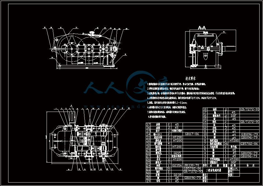
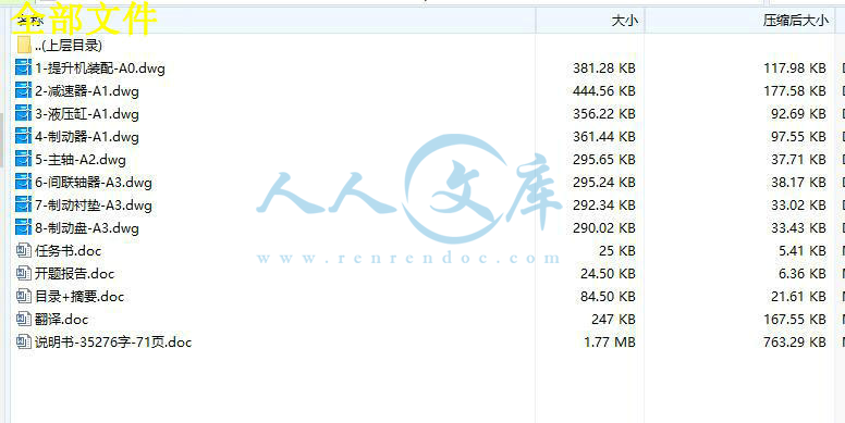
1-提升机装配-A0.dwg
2-减速器-A1.dwg
3-液压缸-A1.dwg
4-制动器-A1.dwg
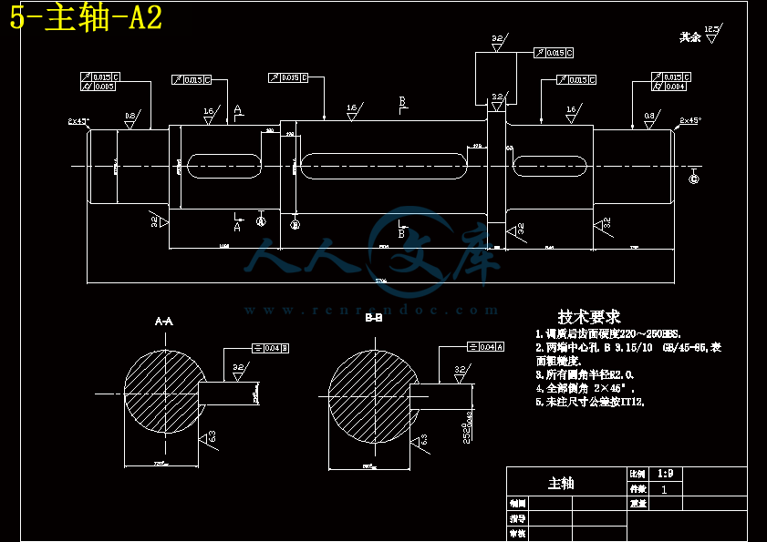
5-主轴-A2.dwg
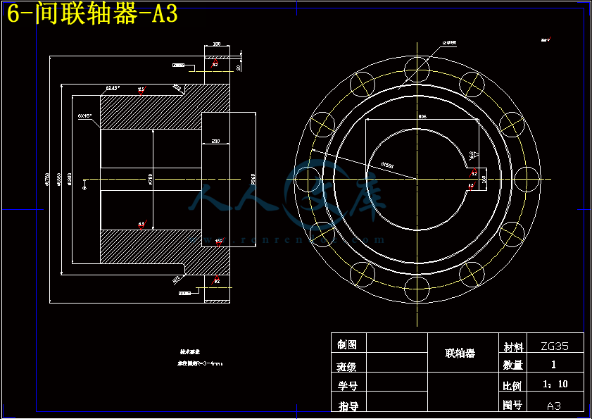
6-间联轴器-A3.dwg
7-制动衬垫-A3.dwg
8-制动盘-A3.dwg
压缩包内文档预览:

资源预览需要最新版本的Flash Player支持。
您尚未安装或版本过低,建议您

摘要矿山提升机是矿山大型固定机械之一,矿山提升机从最初的蒸汽机拖动的单绳缠绕式提升机发展到今天的交交变频直接拖动的多绳摩擦式提升机和双绳缠绕式提升机已经历了170多年的发展历史,它是矿山井下生产系统和地面工业广场相连接的枢纽,被喻为矿山运输的咽喉。因此矿山提升设备在矿山生产的全过程占有重要的地位。根据矿井提升机工作原理和结构的不同,可分为缠绕式提升机和摩擦式提升机。在国内外,多绳摩擦式绞车飞跃发展,其发展速度远远超过单绳缠绕式提升机,这是因为它有着许多单绳缠绕式提升机无法比拟的优点,如提升钢丝绳直径较小,主导轮直径及整个机器的尺寸都相应缩小了,设备重量也减轻了,不需要设置防坠器等。下面是我针对不同的矿井的地质、煤层等情况,进行综合计算分析后,本着安全、经济等原则对这两种提升设备系统进行的选型设计。一个现代化的矿井在提升设备的选型上尤为重要。因为提升设备选型的合理与否,直接关系到矿井的安全和经济性,因此确定合理的提升系统时,必须经过多方面的技术经济比较,结合矿井的具体条件选择合适的设备。关键词:提升机;多绳摩擦;制动器;选型设计AbstractThe mine elevator is one of mine large-scale fixed machineries, the mine elevator the winding type elevator developed from initial steam engine dragging's Shan Sheng to today's junction - - hands over the frequency conversion direct dragging the multi-rope friction type elevator and the double rope winding type elevator has experienced more than 170 year historical developments, it was the key position which the mine shaft production system and the ground industry square connected, is explained for mine haulage's pharynx and larynx. Therefore the mine hoisting equipment holds the important status in the mine production's entire process. According to the mine pit elevator principle of work and the structure difference, may divide into the winding type elevator and the friction type elevator.In domestic and foreign, the multi-rope friction type winch leap development, its development speed goes far beyond the single rope winding type elevator, this is because it has the merit which many single rope winding type elevator is unable to compare, like the hoisting cable diameter was small, leads the wheel diameter and the entire machine's size correspondingly reduced, the installation weight also reduced, did not need to establish against falls and so on. Below is I in view of different situations and so on mine pit geology, coal bed, after carrying on the synthesis computation analysis, in line with principles and so on security, economy the shaping design which carries on to these two kind of lift technique system. A modernized mine pit on lift technique's shaping especially important. Because of lift technique shaping reasonable or not, direct relation mine pit security and efficiency, therefore determined when reasonable lift system, must undergo various technical economy comparison, the union mine pit concrete term choice appropriate equipment.  Keywords:Elevator  The multi-ropes rub  Brake  Shaping design 目       录1 绪论12 矿井提升设备概述32.1 提升机的定义32.2 提升机的分类33 多绳摩擦式提升机的整体设计计算103.1设计依据103.2设计过程10  3.2.1 箕斗的选定10  3.2.2提升刚丝绳的选型12  3.2.3提升机卷筒的选择14  3.2.4提升机的选择15  3.2.5天轮的选择17  3.2.6计算提升机与井筒的相对位置17  3.2.7 预选提升电动机19  3.2.8 计算传动装置的总传动比配传动比20  3.2.9主轴输入功率及轴径的确定20  3.2.10根据轴径确定主轴部分的安装轴承21  3.2.11减速器的设计21  3.2.12联轴器的设计27  3.2.13 提升机各部分键的选择283.3制动器的设计29  3.3.1 提升机制动器主要类型31  3.3.2盘式制动器的结构及工作原理33  3.4液压站工作原理35  3.4.1 提升机液压站系统35  3.4.2 液压站系统原理35  3.4.3 液压站控制电路364 提升设备的运动学及动力学计算384.1提升系统变位质量的计算384.2提升加速度的确定394.3提升减速提升减速度的确定404.4防滑计算41  4.4.1静防滑41  4.4.2动防滑41  4.4.3等速和减速阶段42  4.4.4提升重载发生紧急制动时424.5六阶段速度图参数的计算434.6提升设备的动力学计算454.7提升电动机容量的计算464.8提升设备的电耗及效率的计算48结论50致谢51参考文献52附录53附录1531 绪论矿山提升机是矿山大型固定机械之一,矿山提升机从最初的蒸汽机拖动的单绳缠绕式提升机发展到今天的交交变频直接拖动的多绳摩擦式提升机和双绳缠绕式提升机已经历了170多年的发展历史,它是矿山井下生产系统和地面工业广场相连接的枢纽,被喻为矿山运输的咽喉。因此矿山提升设备在矿山生产的全过程占有重要的地位。一个现代化的矿井在提升设备的选型上尤为重要。因为提升设备选型的合理与否,直接关系到矿井的安全和经济性,因此确定合理的提升系统时,必须经过多方面的技术经济比较,结合矿井的具体条件选择合适的设备。根据矿井提升机工作原理和结构的不同,可分为缠绕式提升机和摩擦式提升机。单绳缠绕式提升机是较早出现的一种,它工作可靠,结构简单,但是仅适用于浅井及中等深度的矿井,而对于井深超过300米的矿井,宜选用多绳摩擦式绞车。在国内外,多绳摩擦式绞车飞跃发展,其发展速度远远超过单绳缠绕式提升机,这是因为它有着许多单绳缠绕式提升机无法比拟的优点,如提升钢丝绳直径较小,主导轮直径及整个机器的尺寸都相应缩小了,设备重量也减轻了,不需要设置防坠器等。下面是我针对不同的矿井的地质、煤层等情况,进行综合计算分析后,本着安全、经济等原则对这两种提升设备系统进行的选型设计。目前我国煤炭95%是以井下方式开采,需要通过提升设备提升到地面以实现其使用价值和经济、社会效益。提升作为重要的一个环节,在一定程度上制约着煤炭生产能力。提升设备的合理结构及设计,安全经济运行和科学管理维护,直接关系到矿井生产能力及技术经济指标。现代采矿业的发展对提升设备在机械结构、工艺、设计理论和方法及安全检测等方面都有明确的要求。矿井提升设备的功能特点及生产的基本环节,提升设备的合理结构及设计、安全经济运行和科学管理维护直接关系到矿井生产能力及经济技术指标。国家将在“十一五”期间对有发展潜力的小煤矿进行改造提升以满足我国目前能源供应紧张的局面,更好的为全面建设社会主义小康社会提供“动力”支持。目前我国中小型煤矿作为我国煤炭生产的重要部分其提升设备同大型煤矿及世界先进水平相比,仍有很大差距,主要表现在:(1)提升设备的自动化水平较低,提升设备自动控制化控制较国内与国外大型和先进煤矿提升系统落后;(2)提升设备的配套产品(钢丝绳、大型电机、减速器等)的质量安全性能尚不能满足要求,在一定程度上制约了提升设备的总体水平;(3)矿井提升的监、检手段落后、制动系统的可靠性明显不足,有待进一步提高。近几年煤炭开采与提升技术的发展速度很快,对提升机的要求必然随着先进技术的进步而不断发展,其发展趋势是:(1)向适用型发展。(2)向高耐久性,高可靠性方向发展。(3)向智能化自动化方向发展。提升系统采用PLC控制监测系统等,并可根据要求调节,信号用声、光、影像来传送。(4)向标准化、规范化方向发展。提升机零部件普遍标准化,规范化,保证设计、加工质量和水平。(5)向高适应性发展。适应不同工作环境。因此,研究制造自己的高效提升机是为经济发展和社会进步的长远考虑。本文首先综合比较了各种类型提升机的特点,根据经济效益和最大程度利用原则的实际情况选用了单绳缠绕式提升机的设计。然后,对多绳摩擦式提升机进行了总体结构设计并对其可靠性和可行性进行了分析。对提升机的主轴装置、联轴器、减速器、制动器等主要部件进行了技术分析和结构设计,完成了多绳摩擦式提升机的整体设计。此次设计的提升机主轴装置、减速器与制动系统是配套专用产品,电动机的选择可以灵活运用。这样可以使提升机的应用、维护、保养、检测等方面系统进行,有效提高提升机的工作效率。多绳摩擦提升机具有体积小、质量轻、安全可靠、提升能力强等优点,适用于较深的矿井提升。 由于水平有限,难免出现错误,请指导老师和专家给予批评和指正。
编号:6037331    类型:共享资源    大小:1.56MB    格式:ZIP    上传时间:2017-10-25 上传人:俊****计 IP属地:江苏
40
积分
关 键 词:
大黄山 煤矿主 提升 设备 选型 设计 8张 cad 图纸 说明书
资源描述:

摘要

矿山提升机是矿山大型固定机械之一,矿山提升机从最初的蒸汽机拖动的单绳缠绕式提升机发展到今天的交——交变频直接拖动的多绳摩擦式提升机和双绳缠绕式提升机已经历了170多年的发展历史,它是矿山井下生产系统和地面工业广场相连接的枢纽,被喻为矿山运输的咽喉。因此矿山提升设备在矿山生产的全过程占有重要的地位。根据矿井提升机工作原理和结构的不同,可分为缠绕式提升机和摩擦式提升机。

在国内外,多绳摩擦式绞车飞跃发展,其发展速度远远超过单绳缠绕式提升机,这是因为它有着许多单绳缠绕式提升机无法比拟的优点,如提升钢丝绳直径较小,主导轮直径及整个机器的尺寸都相应缩小了,设备重量也减轻了,不需要设置防坠器等。

下面是我针对不同的矿井的地质、煤层等情况,进行综合计算分析后,本着安全、经济等原则对这两种提升设备系统进行的选型设计。一个现代化的矿井在提升设备的选型上尤为重要。因为提升设备选型的合理与否,直接关系到矿井的安全和经济性,因此确定合理的提升系统时,必须经过多方面的技术经济比较,结合矿井的具体条件选择合适的设备。


关键词:提升机;多绳摩擦;制动器;选型设计


Abstract

The mine elevator is one of mine large-scale fixed machineries, the mine elevator the winding type elevator developed from initial steam engine dragging's Shan Sheng to today's junction - - hands over the frequency conversion direct dragging the multi-rope friction type elevator and the double rope winding type elevator has experienced more than 170 year historical developments, it was the key position which the mine shaft production system and the ground industry square connected, is explained for mine haulage's pharynx and larynx. Therefore the mine hoisting equipment holds the important status in the mine production's entire process. According to the mine pit elevator principle of work and the structure difference, may divide into the winding type elevator and the friction type elevator.

In domestic and foreign, the multi-rope friction type winch leap development, its development speed goes far beyond the single rope winding type elevator, this is because it has the merit which many single rope winding type elevator is unable to compare, like the hoisting cable diameter was small, leads the wheel diameter and the entire machine's size correspondingly reduced, the installation weight also reduced, did not need to establish against falls and so on. 

Below is I in view of different situations and so on mine pit geology, coal bed, after carrying on the synthesis computation analysis, in line with principles and so on security, economy the shaping design which carries on to these two kind of lift technique system. A modernized mine pit on lift technique's shaping especially important. Because of lift technique shaping reasonable or not, direct relation mine pit security and efficiency, therefore determined when reasonable lift system, must undergo various technical economy comparison, the union mine pit concrete term choice appropriate equipment. 


 Keywords:Elevator  The multi-ropes rub  Brake  Shaping design 


目       录

1 绪论 1

2 矿井提升设备概述 3

2.1 提升机的定义 3

2.2 提升机的分类 3

3 多绳摩擦式提升机的整体设计计算 10

3.1设计依据 10

3.2设计过程 10

  3.2.1 箕斗的选定 10

  3.2.2提升刚丝绳的选型 12

  3.2.3提升机卷筒的选择 14

  3.2.4提升机的选择 15

  3.2.5天轮的选择 17

  3.2.6计算提升机与井筒的相对位置 17

  3.2.7 预选提升电动机 19

  3.2.8 计算传动装置的总传动比配传动比 20

  3.2.9主轴输入功率及轴径的确定 20

  3.2.10根据轴径确定主轴部分的安装轴承 21

  3.2.11减速器的设计 21

  3.2.12联轴器的设计 27

  3.2.13 提升机各部分键的选择 28

3.3制动器的设计 29

  3.3.1 提升机制动器主要类型 31

  3.3.2盘式制动器的结构及工作原理 33

  3.4液压站工作原理 35

  3.4.1 提升机液压站系统 35

  3.4.2 液压站系统原理 35

  3.4.3 液压站控制电路 36

4 提升设备的运动学及动力学计算 38

4.1提升系统变位质量的计算 38

4.2提升加速度的确定 39

4.3提升减速提升减速度的确定 40

4.4防滑计算 41

  4.4.1静防滑 41

  4.4.2动防滑 41

  4.4.3等速和减速阶段 42

  4.4.4提升重载发生紧急制动时 42

4.5六阶段速度图参数的计算 43

4.6提升设备的动力学计算 45

4.7提升电动机容量的计算 46

4.8提升设备的电耗及效率的计算 48

结论 50

致谢 51

参考文献 52

附录 53

附录1 53


1 绪论

矿山提升机是矿山大型固定机械之一,矿山提升机从最初的蒸汽机拖动的单绳缠绕式提升机发展到今天的交——交变频直接拖动的多绳摩擦式提升机和双绳缠绕式提升机已经历了170多年的发展历史,它是矿山井下生产系统和地面工业广场相连接的枢纽,被喻为矿山运输的咽喉。因此矿山提升设备在矿山生产的全过程占有重要的地位。

一个现代化的矿井在提升设备的选型上尤为重要。因为提升设备选型的合理与否,直接关系到矿井的安全和经济性,因此确定合理的提升系统时,必须经过多方面的技术经济比较,结合矿井的具体条件选择合适的设备。

根据矿井提升机工作原理和结构的不同,可分为缠绕式提升机和摩擦式提升机。单绳缠绕式提升机是较早出现的一种,它工作可靠,结构简单,但是仅适用于浅井及中等深度的矿井,而对于井深超过300米的矿井,宜选用多绳摩擦式绞车。在国内外,多绳摩擦式绞车飞跃发展,其发展速度远远超过单绳缠绕式提升机,这是因为它有着许多单绳缠绕式提升机无法比拟的优点,如提升钢丝绳直径较小,主导轮直径及整个机器的尺寸都相应缩小了,设备重量也减轻了,不需要设置防坠器等。下面是我针对不同的矿井的地质、煤层等情况,进行综合计算分析后,本着安全、经济等原则对这两种提升设备系统进行的选型设计。

目前我国煤炭95%是以井下方式开采,需要通过提升设备提升到地面以实现其使用价值和经济、社会效益。提升作为重要的一个环节,在一定程度上制约着煤炭生产能力。提升设备的合理结构及设计,安全经济运行和科学管理维护,直接关系到矿井生产能力及技术经济指标。现代采矿业的发展对提升设备在机械结构、工艺、设计理论和方法及安全检测等方面都有明确的要求。矿井提升设备的功能特点及生产的基本环节,提升设备的合理结构及设计、安全经济运行和科学管理维护直接关系到矿井生产能力及经济技术指标。国家将在“十一五”期间对有发展潜力的小煤矿进行改造提升以满足我国目前能源供应紧张的局面,更好的为全面建设社会主义小康社会提供“动力”支持。

目前我国中小型煤矿作为我国煤炭生产的重要部分其提升设备同大型煤矿及世界先进水平相比,仍有很大差距,主要表现在:

(1)提升设备的自动化水平较低,提升设备自动控制化控制较国内与国外大型和先进煤矿提升系统落后;

(2)提升设备的配套产品(钢丝绳、大型电机、减速器等)的质量安全性能尚不能满足要求,在一定程度上制约了提升设备的总体水平;

(3)矿井提升的监、检手段落后、制动系统的可靠性明显不足,有待进一步提高。

近几年煤炭开采与提升技术的发展速度很快,对提升机的要求必然随着先进技术的进步而不断发展,其发展趋势是:

(1)向适用型发展。

(2)向高耐久性,高可靠性方向发展。

(3)向智能化自动化方向发展。提升系统采用PLC控制监测系统等,并可根据要求调节,信号用声、光、影像来传送。

(4)向标准化、规范化方向发展。提升机零部件普遍标准化,规范化,保证设计、加工质量和水平。

(5)向高适应性发展。适应不同工作环境。

因此,研究制造自己的高效提升机是为经济发展和社会进步的长远考虑。本文首先综合比较了各种类型提升机的特点,根据经济效益和最大程度利用原则的实际情况选用了单绳缠绕式提升机的设计。然后,对多绳摩擦式提升机进行了总体结构设计并对其可靠性和可行性进行了分析。对提升机的主轴装置、联轴器、减速器、制动器等主要部件进行了技术分析和结构设计,完成了多绳摩擦式提升机的整体设计。此次设计的提升机主轴装置、减速器与制动系统是配套专用产品,电动机的选择可以灵活运用。这样可以使提升机的应用、维护、保养、检测等方面系统进行,有效提高提升机的工作效率。多绳摩擦提升机具有体积小、质量轻、安全可靠、提升能力强等优点,适用于较深的矿井提升。

 由于水平有限,难免出现错误,请指导老师和专家给予批评和指正。


内容简介:
徐州工程学院毕 业 设 计 ( 论 文 ) 任 务 书机电工程 学院 机械设计制造及自动化 专业设计(论文)题目 大黄山煤矿主井提升设备选型设计 学 生 姓 名 程旭 班 级 04 机本 2 班 起 止 日 期 2008.2.25 2008.6.2指 导 教 师 熊永超 教 研 室 主 任 熊 永 超 发任务书日期 2008 年 02 月 25 日1.毕业设计的背景:一个现代化的矿井在提升设备的选型上尤为重要。因为提升设备选型的合理与否,直接关系到矿井的安全和经济性,因此确定合理的提升系统时,必须经过多方面的技术经济比较,结合矿井的具体条件选择合适的设备。所以,本次设计任务就是根据矿井的年产量,年(日)工作时间,井深,以及矿井的本身的特点等重要指标来进行对提升机的合理选用。从而使得该矿井生产能力达到其最大的优化配置。2.毕业设计(论文)的内容和要求:本次设计是针对为了使某矿井能够达到其最优化的生产而做出的对提升机的合理选型的一个主要过程。本次设计首先综合比较了各种类提升机的特点,并且根据经济效益和最大程度利用原则的实际情况选择了多绳摩擦式提升机。其次,对多绳摩擦式提升机记性总体结构设计并对其可靠性和可行性进行合理分析。对提升机的主轴装置、联轴器、减速器、制动器等主要部件进行了技术分析和结构设计,完成了多绳摩擦式提升机的整体设计。此次设计的提升机主轴装置,减速器与制动系统是配套专用产品,电动机的选择可以灵活运用。最终的要求就是能够使提 升机的应用,维护,保养,测试等方面都能够正常的,系统的进行,从而有效的提高该矿井的整体工作效率。3.主要参考文献:1 潘英矿山提升机机械设计徐州:中国矿业大学出版社,20012 葛世荣矿井提升机可靠性技术徐州:中国矿业大学出版社,19943 麻健,李勇忠提升机新型液压制动系统煤矿机械,19994 许福玲 ,陈晓明液压与气压传动北京:机械工业出版社,2004.75 孙玉蓉,周法孔 .矿井提升设备. 煤炭工业出版社,19954.毕业设计(论文)进度计划(以周为单位):起 止 日 期 工 作 内 容 备 注第 1-2 周第 3-4 周第 5-6 周第 7-8 周第 9-10 周第 11-12 周第 13-14 周第 15-16 周根据毕业设计任务书,进行实地实习和收集资料,完成开题报告,查阅外文翻译根据收集到的相关资料和实际情况确定方案设计根据已知数据对多绳摩擦式矿井提升机设备选型进行设计对已经选定的设备进行各种验算并绘制设备总装图草图绘制总装图图纸绘制减速器、主轴图纸并对图纸做出相应的改正按照规格和选型设计所计算的结果开始写说明提交说明书和图纸,复习设计内容,准备毕业答辩教研室审查意见:室主任 年 月 日学院审查意见:教学院长 年 月 日徐州工程学院毕业设计(论文)开题报告课 题 名 称: 大黄山煤矿主井提升设备选型设计 学 生 姓 名: 程旭 学号: 52 号 指 导 教 师: 熊永超 职称: 教授 所 在 学 院: 机电工程学院 专 业 名 称: 机械设计制造及其自动化 徐州工程学院2008 年 03 月 04 日说 明1根据徐州工程学院毕业设计(论文)管理规定,学生必须撰写毕业设计(论文)开题报告,由指导教师签署意见、教研室审查,学院教学院长批准后实施。2开题报告是毕业设计(论文)答辩委员会对学生答辩资格审查的依据材料之一。学生应当在毕业设计(论文)工作前期内完成,开题报告不合格者不得参加答辩。3毕业设计开题报告各项内容要实事求是,逐条认真填写。其中的文字表达要明确、严谨, 语言通顺,外来 语 要同时用原文和中文表达。第一次出现缩写词,须注出全称。4本报告中,由学生本人撰写的对课题和研究工作的分析及描述,没有经过整理归纳,缺乏个人见解仅仅从网上下载材料拼凑而成的开题报告按不合格论。5. 课题类型填:工程设计类;理论研究类;应用(实验)研究类;软件设计类;其它。6、课题来源填:教师科研;社会生产实践;教学;其它课题名称大黄山煤矿主井提升设备选型设计课题来源 模拟生产实际课题 课题类型 应用研究选题的背景及意义一个现代化的矿井在提升设备的选型上尤为重要。因为提升设备选型的合理与否,直接关系到矿井的安全和经济性,因此确定合理的提升系统时,必须经过多方面的技术经济比较,结合矿井的具体条件选择合适的设备。所以,本次设计任务就是根据矿井的年产量,年(日)工作时间以及井深等重要指标进行对提升机的合理选用。从而使得该矿井生产能力达到最大的优化配置。研究内容拟解决的主要问题需要解决的问题主要是以下几点:(1)提升钢丝绳的合理选用及维护;(2)提升机的合理选用,及主要制动装置的分析;(3)提升机与井筒的相对位置的计算;(4)矿井提升运动学及动力学计算;(5)多绳摩擦的安全传动及安全摩擦系数的计算;(6)电动机的选择,提升设备的电耗及效率的计算。研究方法技术路线首先要综合比较各种类型提升机的特点,根据经济效益和最大程度利用原则的实际情况选用适合本次设计的提升机。然后,对选好的多绳摩擦式提升机进行总体结构设计并对其可靠性和可行性进行分析。对提升机的主轴装置、联轴器、减速器、制动器等主要部件进行技术分析和结构设计,完成了多绳摩擦式提升机的整体设计。此次设计的提升机主轴装置、减速器与制动系统是配套专用产品,电动机的选择可以灵活运用。这样可以使提升机的应用、维护、保养、检测等方面系统环节能够正常有序的进行,从而有效提高矿井的工作效率。研究的总体安排和进度计划第 1-2 周:根据毕业设计任务书,进行实地实习和收集资料,完成开题报告,查阅外文翻译第 3-4 周:根据收集到的相关资料和实际情况确定方案设计第 5-6 周:根据已知数据对多绳摩擦式矿井提升机设备选型进行设计第 7-8 周:对已经选定的设备进行各种验算并绘制设备总装图草图第 9-10 周:绘制总装图图纸第 11-12 周:绘制减速器、主轴图纸并对图纸做出相应的改正第 13-14 周:按照规格和选型设计所计算的结果开始写说明第第 15-16 周:提交说明书和图纸,复习设计内容,准备毕业答辩主要参考文献1 潘英矿山提升机机械设计徐州:中国矿业大学出版社,20012 葛世荣矿井提升机可靠性技术徐州:中国矿业大学出版社,19943 麻健,李勇忠提升机新型液压制动系统煤矿机械,19994 许福玲,陈晓明液压与气压传动北京:机械工业出版社,2004.75 孙玉蓉,周法孔 .矿井提升设备. 煤炭工业出版社,1995指导教师意 见指导教师签名:年 月 日 教研室意见 学院意见教研室主任签名:年 月 日教学院长签名:年 月 日徐 州 工 程 学 院 毕 业 设 计 (论 文 )I摘要矿山提升机是矿山大型固定机械之一,矿山提升机从最初的蒸汽机拖动的单绳缠绕式提升机发展到今天的交交变频直接拖动的多绳摩擦式提升机和双绳缠绕式提升机已经历了 170 多年的发展历史,它是矿山井下生产系统和地面工业广场相连接的枢纽,被喻为矿山运输的咽喉。因此矿山提升设备在矿山生产的全过程占有重要的地位。根据矿井提升机工作原理和结构的不同,可分为缠绕式提升机和摩擦式提升机。在国内外,多绳摩擦式绞车飞跃发展,其发展速度远远超过单绳缠绕式提升机,这是因为它有着许多单绳缠绕式提升机无法比拟的优点,如提升钢丝绳直径较小,主导轮直径及整个机器的尺寸都相应缩小了,设备重量也减轻了,不需要设置防坠器等。下面是我针对不同的矿井的地质、煤层等情况,进行综合计算分析后,本着安全、经济等原则对这两种提升设备系统进行的选型设计。一个现代化的矿井在提升设备的选型上尤为重要。因为提升设备选型的合理与否,直接关系到矿井的安全和经济性,因此确定合理的提升系统时,必须经过多方面的技术经济比较,结合矿井的具体条件选择合适的设备。关键词:提升机;多绳摩擦;制动器;选型设计徐 州 工 程 学 院 毕 业 设 计 (论 文 )IIAbstractThe mine elevator is one of mine large-scale fixed machineries, the mine elevator the winding type elevator developed from initial steam engine draggings Shan Sheng to todays junction - - hands over the frequency conversion direct dragging the multi-rope friction type elevator and the double rope winding type elevator has experienced more than 170 year historical developments, it was the key position which the mine shaft production system and the ground industry square connected, is explained for mine haulages pharynx and larynx. Therefore the mine hoisting equipment holds the important status in the mine productions entire process. According to the mine pit elevator principle of work and the structure difference, may divide into the winding type elevator and the friction type elevator.In domestic and foreign, the multi-rope friction type winch leap development, its development speed goes far beyond the single rope winding type elevator, this is because it has the merit which many single rope winding type elevator is unable to compare, like the hoisting cable diameter was small, leads the wheel diameter and the entire machines size correspondingly reduced, the installation weight also reduced, did not need to establish against falls and so on. Below is I in view of different situations and so on mine pit geology, coal bed, after carrying on the synthesis computation analysis, in line with principles and so on security, economy the shaping design which carries on to these two kind of lift technique system. A modernized mine pit on lift techniques shaping especially important. Because of lift technique shaping reasonable or not, direct relation mine pit security and efficiency, therefore determined when reasonable lift system, must undergo various technical economy comparison, the union mine pit concrete term choice appropriate equipment. Keywords:Elevator The multi-ropes rub Brake Shaping design 徐 州 工 程 学 院 毕 业 设 计 (论 文 )I目 录1 绪论 .12 矿井提升设备概述 .32.1 提升机的定义 .32.2 提升机的分类 .33 多绳摩擦式提升机的整体设计计算 .103.1 设计依据 .103.2 设计过程 .103.2.1 箕斗的选定 .103.2.2 提升刚丝绳的选型 .123.2.3 提升机卷筒的选择 .143.2.4 提升机的选择 .153.2.5 天轮的选择 .173.2.6 计算提升机与井筒的相对位置 .173.2.7 预选提升电动机 .193.2.8 计算传动装置的总传动比 配传动比 .20i3.2.9 主轴输入功率及轴径的确定 .203.2.10 根据轴径确定主轴部分的安装轴承 .213.2.11 减速器的设计 .213.2.12 联轴器的设计 .273.2.13 提升机各部分键的选择 .283.3 制动器的设计 .293.3.1 提升机制动器主要类型 .313.3.2 盘式制动器的结构及工作原理 .333.4 液压站工作原理 .353.4.1 提升机液压站系统 .353.4.2 液压站系统原理 .353.4.3 液压站控制电路 .364 提升设备的运动学及动力学计算 .384.1 提升系统变位质量的计算 .384.2 提升加速度的确定 .394.3 提升减速提升减速度的确定 .404.4 防滑计算 .414.4.1 静防滑 .41徐 州 工 程 学 院 毕 业 设 计 (论 文 )II4.4.2 动防滑 .414.4.3 等速和减速阶段 .424.4.4 提升重载发生紧急制动时 .424.5 六阶段速度图参数的计算 .434.6 提升设备的动力学计算 .454.7 提升电动机容量的计算 .464.8 提升设备的电耗及效率的计算 .48结论 .50致谢 .51参考文献 .52附录 .53附录 1 .53徐 州 工 程 学 院 毕 业 设 计 (论 文 )33附录附录 1英文原文Reflections regarding uncertainty of measurement, on the results of a Nordic fatigue test interlaboratory comparisonMagnus Holmgren, Thomas Svensson, Erland Johnson, Klas JohanssonAbstract This paper presents the experiences of calculation and reporting uncertainty of measurement in fatigue testing. Six Nordic laboratories performed fatigue tests on steel specimens. The laboratories also reported their results concerning uncertainty of measurement and how they calculated it. The results show large differences in the way the uncertainties of measurement were calculated and reported. No laboratory included the most significant uncertainty source, bending stress (due to misalignment of the testing machine, “incorrect” specimens and/or incorrectly mounted specimens), when calculating the uncertainty of measurement. Several laboratories did not calculate the uncertainty of measurement in accordance with the Guide to the Expression of Uncertainty in Measurement (GUM) 1.Keyword: Uncertainty of measurement, Calculation, Report, Fatigue test, Laboratory intercomparisonDefinitions :R Stress ratio Fmin/Fmax F Force (nektons) A and B Fatigue strength parameters s and S Stress (megapascals) N Number of cycles. IntroductionThe correct or best method of calculating and reporting uncertainty of measurement in testing has been the subject of discussion for many years. The issue became even more relevant in connection with the introduction of ISO standards, e.g. ISO17025 2. The discussion, as well as implementation of the uncertainty of measurement concept, has often been concentrated on which equation to use or on administrative handling of the issue. There has been less interest in the technical problem and how to handle uncertainty of measurement in the actual experimental situation, and how to learn from the uncertainty of measurement calculation when improving the experimental technique. One reason for this may be that the accreditation bodies have concentrated on the very existence of uncertainty of measurement calculations for an accredited test method, instead of on whether the calculations are performed in a sound technical way. The present investigation emphasizes the need for a more technical focus.One testing area where it is difficult to do uncertainty of measurement calculations is fatigue testing. However, there is guidance on how to perform such calculations, e.g. in Refs. 3, 4. To investigate how uncertainty of measurement calculations are performed for fatigue tests in real life, UTMIS (the Swedish fatigue network) started an interlaboratory comparison where one 4of the most essential parts was to calculate and report the uncertainty of measurement of a typical fatigue test that could have been ordered by a customer of the participating laboratories. For cost reasons, customers often ask for a limited number of test specimens but, at the same time, they request a lot of information about a large portion of the possible stress-life area from few cycles (high stresses) to millions of cycles (low stresses) and even run-outs. The way the calculation was made should also be reported. The outcome concerning the uncertainty of measurement from the project is reported in this article.ParticipantsSix Nordic laboratories participated in the interlaboratory comparison: one industrial laboratory, two research institutes, two university laboratories and one laboratory in a consultancy company. Two of the laboratories are accredited for fatigue testing, and a third laboratory is accredited for other tests. Each participant was randomly assigned a number between 1 and 6, and this notification will be used in the rest of this paper.Experimental procedureThe participants received information about the test specimens (without material data), together with instructions on the way to perform the test and how to report the results.The instructions were that tests should be performed as constant load amplitude tests, with R=0.1 at three different stress levels, 460, 430 and 400 Map, with four specimens at each stress level, at a test frequency between 10 and 30 Hz, with a run-out limit at cycles and in a 6510normal laboratory climate ( and relative humidity). This was considered as a 023C51%typical customer ordered test.The test results were to be used to calculate estimates of the two fatigue strength parameters, A and B, according to linear regression of the logs and long variables, i.e. . loglogABNThe reported result should include both the estimated parameters A and B and the uncertainties in them due to measurement errors. The report should also include the considerations and calculations behind the results, especially those concerning uncertainty of measurement.Several properties were to be reported for each specimen. The most important one was the number of cycles until fracture or if the specimen was a run-out (i.e. survived for cycles).6510The tests were to be performed in accordance with ASTM E-46696 5 and ISO5725-2 6. ASTM E-466-96 does not take uncertainty of measurement into account;However, ASTM E-466-96 mentions that the bending stress introduced owing to misalignment must not exceed 5% of the greater of the range, maximum or minimum stresses. There are also requirements for the accuracy of the dimensional measurement of the test specimen.All participants used hydraulic testing machines. The test specimens were made of steel (yield stress 375390 Map, and tensile strength 670690 Map, tabulated values). The test specimens were distributed to the participants by the organizer.ResultsThe primary laboratory results that should be compared are the estimated Whaler curves. In 5order to present all results in the same way, the organizer transformed some of the results. The Whaler curves reported by the participants are shown in Fig. 1.It can be seen that there are considerable differences between laboratories. An approximate statistical test shows a significant laboratory effect. Material scatter alone cannot explain the differences in the Whaler curves. In order to investigate if the laboratory effect was solely caused by the modeling uncertainty, we estimated new parameters from the raw data with a common algorithm. We then chose to use only the failed specimens and to make the minimization in the logarithmic life direction. The results are shown in Fig. 2. A formal statistical significance test was then made, and the result of such a test shows that the differences between the laboratories shown in Fig. 1 could be attributed only to modeling.Uncertainty of measurement calculationsOne of the most important objectives with this investigation was to compare the observed differences between laboratory test results with their estimated uncertainties of measurement. The intention was to analyze the uncertainty analyses as such, and to compare them to the standard procedure recommended in the ISO guide: Guide to the Expression of Uncertainty in Measurement (GUM) 1.The laboratories identified different sources of uncertainty and treated them in different ways. These sources are the load measurement, the load control, the superimposed bending stresses because of misalignment and the dimensional measurements. Implicitly, laboratory temperature and humidity, specimen temperature and corrosion effects are also considered. In addition, the results show a modeling effect. The different laboratory treatments of these sources are summarized in Table 1.Specific comments on the different laboratoriesAll laboratories gave their laboratory temperature and humidity, but did not consider these values as sources of uncertainty, i.e. the influence of temperature and humidity was neglected. This conclusion is reasonable for steel in the temperature range and humidity range in question 7.Laboratory 1. The uncertainty due to the applied stress was determined taking load cell and dimensional uncertainties into account. The mathematical evaluation was made in accordance with the GUM. Specimen temperature was measured, but was implicitly neglected. The modeling problem was mentioned, but not considered as an uncertainty source. Laboratory 2. The report contains no uncertainty evaluation. The uncertainties in the load cell and the micrometer are considered, but neglected with reference to the large material scatter. Specimen temperature was measured. Modeling problems are mentioned by a comment regarding the choice of load levels.Laboratory 3. The report contains no uncertainty evaluation. However, the accuracy of the machine is given and the load was controlled during the tests to be within specified limits. The 6bending stresses were measured on one specimen, but their influence on the fatigue result was not taken into consideration. Laboratory 4. The uncertainties in the load cell and the dimensional measurements are considered in an evaluation of stress uncertainty. The method for the evaluation is not in accordance with the GUM method, but was performed by adding absolute errors. The bending stress influence and the control system deviations are considered, but not included in the uncertainty evaluation. The failure criterion is mentioned and regarded as negligible, and corrosion is mentioned as a possible source of uncertainty. Laboratory 5. Uncertainties in the load cell and the load control were considered, and the laboratory stated in the report that the evaluation of the load uncertainty was performed according to the CIPM method. Laboratory 6. No report was provided, but only experimental results and a Whaler curve estimate.No laboratory reported the uncertainty in the estimated material properties, the Whaler parameters, but at most the uncertainty in the applied stress. The overall picture of the uncertainty considerations is that only uncertainty sources that are possible to estimate from calibration reports were taken into account in the final evaluation.Fig. 1 All experimental results and estimated Whole curves from the different laboratoriesNumber of cycles to failureOne important source that several laboratories mentioned is the bending stresses induced by misalignment in the testing machine, incorrectly mounted test specimens or “incorrect” specimens. The amount of bending stress was also estimated in some cases, but its influence on the uncertainty in the final Whole curve was not investigated.7The results from this experimental investigation show that there are different ways of determining the Whole curve from the experimental result. One problem is the surviving specimens, the run-out results. Four laboratories used only the failed specimens results for the curve-fit, one laboratory neglected all results at the lowest level, and one laboratory included the run-outs in the estimation. Another problem is the mathematical procedure for estimating the curve. Common practice, and the recommendation in the ASTM standard, is that the curve should be estimated by minimizing the squared errors in log life, i.e. the statistical model is, (1)logllogNabSWhere e is a random error, assumed to have constant variance, and where log stands for the logarithm with base 10. E can be interpreted as the combination of at least two types of errors: namely (1) a random error due to the scatter in the material properties, and (2) a measurement error due to uncertainties in the measurement procedures.Fig. 2 All experimental results and estimated Whole curves using the common procedureNumber of cycles to failureTable 1 Sources of uncertainty and laboratory treatment8C The laboratory report considers the source explicitly or implicitly, N the laboratory report neglects the source, A the laboratory report takes the source into account in the uncertainty of measurement calculationWhere e is a random error, assumed to have constant variance, and where log stands for the logarithm with base 10. E can be interpreted as the combination of at least two types of errors: namely (1) a random error due to the scatter in the material properties, and (2) a measurement error due to uncertainties in the measurement procedures. Stress was minimized, which led to a model discrepancy as discussed in the following.DiscussionExperimental resultsMost laboratories performed estimations of the Whaler curve parameters. Visual comparison of their estimated curves suggests differences, and a statistical test verified the conclusion that there is a statistically significant laboratory effect. A closer study of each participants procedure for determining the Whaler curve shows that the differences seem to be caused by different modeling of the curve.Since the test was intended to simulate a customer ordered test, some specific problems occurred. First, the number of test specimens is limited and therefore one should be careful when drawing conclusions from the results, since the scatter is considerable in fatigue and the number of specimens are limited.Another problem that occurred was that, since run-outs were wanted, two different failure criteria (failure mechanisms) were used to halt the test: fracture of the test specimen or 6510cycles. In the latter case, the use of the equation may cause problems, see loglogABNlater.The investigator then looked at whether any laboratory differences remained after excluding the model interpretation effects. This was accomplished in two ways:Namely, firstly by direct comparison of the experimental fatigue lives obtained, and secondly by using the same estimating procedure on all data sets. This therefore tested whether any laboratory differences remained or not. The first comparison was done on the two higher load levels. For these, no statistically significant differences were found. The second comparison, which included the failuresOn the lowest level, verified the result. Since the variation between laboratories is larger than the variation within a laboratory no statistically significant variation within a laboratory can be distinguished from the totalVariation in material.The conclusion is that no systematic errors in measurements were detected, but different modeling techniques give significant differences in the results. This in fact indicates that when different fitting models are used different quantities are measured even though they have the same name. Before any agreement is reached about the way of reporting fatigue data, it is of 9utmost importance that the modeling procedure is clearly defined in the test report. It is very important for the laboratories customers to be aware of this fact and, when requesting a test, to ask for a preferred modeling procedure as well as to be aware of the modeling procedure used by the laboratory when using fatigue data in design.Uncertainty evaluationAll laboratories made some considerations regarding the uncertainties of measurement. However, none of them evaluated uncertainties for the resulting Whole parameters, but only for the applied stress. However, none of the measurement uncertainties reported are unrealistic considering the factors taken into account, this is based inexperience. Since the specimens were destroyed during the tests it is not possible to separate the material variation from the repeatability. An estimate of the combined measurement uncertainty and the variation in material isAbout 30% of the lifetime and the major contribution are from the material variation and therefore one conclusion is that the measurement uncertainty in this test could be neglected during this test. This is not true for all fatigue tests and it is therefore anyhow interesting to study how the participants treated measurement uncertainty.Only one participant used the method recommended by the ISO guide GUM. This is surprising, since European accreditation authorities have recommended the GUM for several years. Among the uncertainty sources that were identified by the laboratories, only load cell measurement uncertainties and dimensional measurement uncertainties were taken into account. Important sources such as misalignment and load control were identified by some participants but were not included in the evaluation of stress uncertainty. Apparently only calibrated devices were considered for the overall uncertainty, and other sources, more difficult to evaluate, were excluded. No motivation for these exclusions can be found in the reports. One participant rejected the uncertainty evaluation with reference to the large scatter in fatigue lives. Our overall conclusion from the laboratory comparisons, that there are no detectable systematic effects, may be seen as verification of this rejection, but it is questionable if this was an obvious result beforehand. In contrast, for instance, uncertainties due to misalignment are not obviously negligible in comparison with the material scatter, and should be considered in an uncertainty analysis. This investigation, together with other observations 8, 9, shows problems with the introduction of the ISO17025 requirement for uncertainty of measurement statements. The reasons for this may be that the uncertainty of measurement discussion during recent years has concentrated very much on which equation to use and on administrative aspects, e.g. whether the uncertainty of measurement should alwa
温馨提示:
1: 本站所有资源如无特殊说明,都需要本地电脑安装OFFICE2007和PDF阅读器。图纸软件为CAD,CAXA,PROE,UG,SolidWorks等.压缩文件请下载最新的WinRAR软件解压。
2: 本站的文档不包含任何第三方提供的附件图纸等,如果需要附件,请联系上传者。文件的所有权益归上传用户所有。
3.本站RAR压缩包中若带图纸,网页内容里面会有图纸预览,若没有图纸预览就没有图纸。
4. 未经权益所有人同意不得将文件中的内容挪作商业或盈利用途。
5. 人人文库网仅提供信息存储空间,仅对用户上传内容的表现方式做保护处理,对用户上传分享的文档内容本身不做任何修改或编辑,并不能对任何下载内容负责。
6. 下载文件中如有侵权或不适当内容,请与我们联系,我们立即纠正。
7. 本站不保证下载资源的准确性、安全性和完整性, 同时也不承担用户因使用这些下载资源对自己和他人造成任何形式的伤害或损失。
提示  人人文库网所有资源均是用户自行上传分享,仅供网友学习交流,未经上传用户书面授权,请勿作他用。
关于本文
本文标题:大黄山煤矿主井提升设备选型设计【8张CAD图纸和说明书】
链接地址:https://www.renrendoc.com/p-6037331.html

官方联系方式

2:不支持迅雷下载,请使用浏览器下载   
3:不支持QQ浏览器下载,请用其他浏览器   
4:下载后的文档和图纸-无水印   
5:文档经过压缩,下载后原文更清晰   
关于我们 - 网站声明 - 网站地图 - 资源地图 - 友情链接 - 网站客服 - 联系我们

网站客服QQ:2881952447     

copyright@ 2020-2025  renrendoc.com 人人文库版权所有   联系电话:400-852-1180

备案号:蜀ICP备2022000484号-2       经营许可证: 川B2-20220663       公网安备川公网安备: 51019002004831号

本站为文档C2C交易模式,即用户上传的文档直接被用户下载,本站只是中间服务平台,本站所有文档下载所得的收益归上传人(含作者)所有。人人文库网仅提供信息存储空间,仅对用户上传内容的表现方式做保护处理,对上载内容本身不做任何修改或编辑。若文档所含内容侵犯了您的版权或隐私,请立即通知人人文库网,我们立即给予删除!