【温馨提示】 购买原稿文件请充值后自助下载。
以下预览截图到的都有源文件,图纸是CAD,文档是WORD,下载后即可获得。
预览截图请勿抄袭,原稿文件完整清晰,无水印,可编辑。
有疑问可以咨询QQ:414951605或1304139763
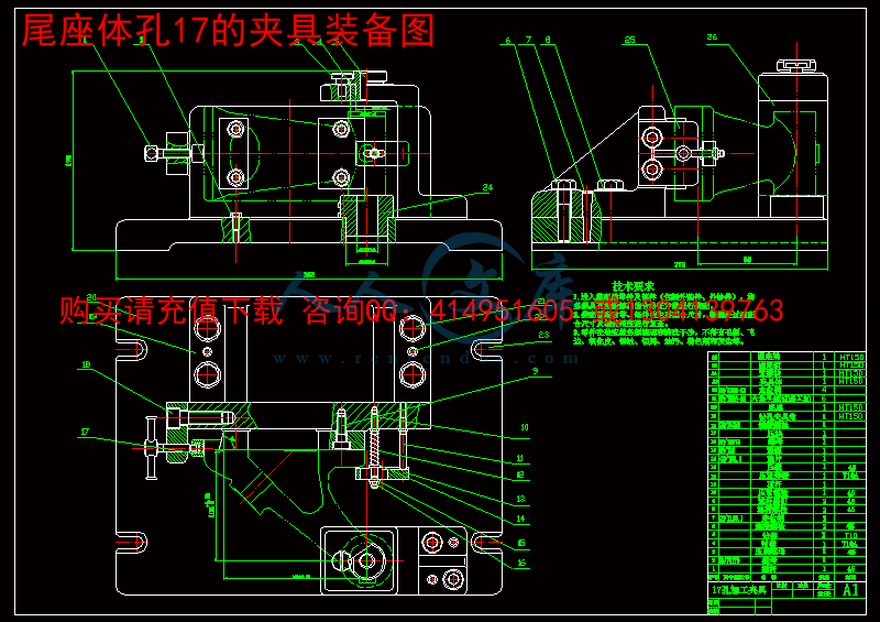
摘要:我要完成的任务是写出尾座体零件的加工工艺规程和设计加工孔φ17的专用夹具。查看零件图找出主要的面和孔,分析它们的结构和工艺特征,计算出重要的参数,选择出合适的机床、夹具、刀具等。编写工艺步骤。设计孔φ17的夹具,以导轨平面作为主定位面限制3个自由度,75度斜面作为侧定位面限制2个自由度。以更好的保证孔φ17的位置和加工精度。再在孔φ17的不加工面找个定位加紧点限制一个自由度,确保六点定位。
关键词:加工工艺;夹具;尾座体;设计
The tailstock body parts machining process planning and the fixture design
Abstract:This topic is mainly design that designs the tail a body of some tool machine to process the craft and tongses, adopting to design first in the design a body of that tail processes the craft at according to process the craft to select by examinations the tongs of the project of the design and concrete design of the tongs;But the point of design is the design of the tongs.Because bore 17 of accuracy have high request, and position the size error margin small, for guarantee the position of the bore and process the accuracy we certainly at process the bottom to face of time pass to draw the line to find out the bottom to face of process the amount of remaining.Thus can with better assurance bore 17 of position and process the accuracy!Process the bore 17 of time is opposite for assurance to run parallel with B face of in the A we have to design accurately with the AN and B faces to settle for of tongs!Return in consideration of a degree of the work piece and the error margin of the cylinder degrees are small, the furniture that we design have to the bore 17 of tongs fixed position is accurate, and process the vibration of time small, that have to in the bore 17 of neighborhood seek a fixed position to step up the point.
Keyword : process the craft;tongs;a body of tail;design
目 录
摘要 I
Abstract II
目录 III
1绪论 1
1.1 设计的依据、背景以及研究意义 1
1.2 国内外研究现状 1
1.2.1 国外研究现状 1
1.2.2 国内研究现状 2
1.3 主要研究内容 3
2 零件分析 4
2.1 零件的特点 4
2.2 零件工艺分析 4
3 机械加工工艺规程设计 5
3.1 确定毛坯的制造形成 5
3.2 基面的选择 5
3.3 制定工艺路线 5
3.3.1 工艺路线方案一 5
3.3.2 工艺路线方案二 6
3.3.3 工艺方案的比较分析 6
3.4 选择加工方法,制定工艺路线 8
3.4.1 孔的端面孔 8
3.4.2 内孔 9
3.4.3 燕尾面加工 9
3.4.4 导轨面刨削加工 10
3.4.5 孔的内径表面 10
3.5 确定切削用量及基本工时 11
3.5.1 铣削的孔的两端面 11
3.5.2 钻孔 12
3.5.3 铣削的孔的端面 12
3.5.4 铣削M6的端面 13
3.5.5 钻、M6孔 14
3.5.6 扩孔 15
3.5.7 加工的倒角 15
3.5.8 扩孔 15
3.5.9 刨削导轨面 16
3.5.10 铣削22的退刀槽 18
3.5.11 刨削燕尾面 18
3.5.12 镗削(精镗、细镗的孔) 19
3.5.13 磨削(导轨面、燕尾面) 19
3.5.14 镗削(镗削的孔、镗削的沉降孔) 21
3.5.15 攻丝 22
3.5.16 导轨面配刮 22
3.5.17 珩磨的孔 22
3.5.18 精加工的孔研配 23
3.5.19 终检 23
4 夹具设计 24
4.1 问题的提出 24
4.2 夹具设计 24
4.2.1 主视图孔的加工夹具 24
5 结论 27
参考文献 29
致谢 31
1 绪论
1.1 设计的依据、背景以及研究意义
随着科研的深入研究与创新,我国的机械制造业得到了长足的发展。在机械制造行业中,产品的材料、结构设计、工艺制造能力等是产品设计的物质技术基础,在制造技术方面对设计提出了许多要求,制约着设计;另一方面,制造技术也在不断的发展完善,同时也在推动着设计。技术不仅是物质基础,并且其本身也很重要。我们要了解材料的物理,化学性能,合理的加工材料,发挥材料和技术的潜在“功能”[1]。技术是发展的基础,发现新材料,创造新工艺,必然会使产品有了新的结构形态和造型样式[2-3]。
制造业的迅速发展,对产品的种类和生产率提出了更高的要求,为了适应中小批量,必然对机床夹具提出更高的要求[4-5]。
尾座体零件在制造业中运用很广,所以对它的要求很高。选用HT150来铸造该零件,HT150是一种脆性较高,硬度较低的材料,因此在尾座体加工时,需要使用高精度机床,另外也要选取合理的夹具,因为夹具设计是否合理将直接影响零件的精度和性能。
这次设计是对大学四年来所学课程及相关应用绘图软件的一次全面性 的总复习,也是一次理论联系实际的训练。其目的在于:
(1) 巩固我们在大学里所学的知识,也是对以前所学知识的检验;
(2) 加强我们查阅资料的能力;
(3) 学习设计思路,掌握设计步骤,完成设计。
(4) 经过这次设计,我对零件的工艺规程设计,设计工艺方案比较并选用合理方案,计算零件加工余量,选用恰当的工艺尺寸,查阅相关资料文献等方面有了很大提高。
(5) 学习CAD,画出任务书中所要求的装配图和零件图。


 川公网安备: 51019002004831号