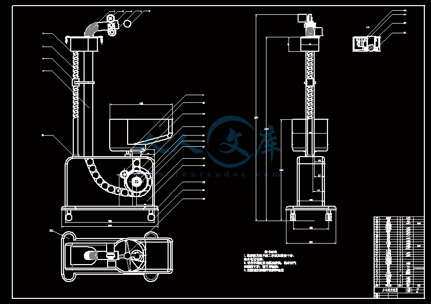
乒乓球发球器的结构设计【全套含有CAD图纸三维建模】
收藏
资源目录

压缩包内文档预览:(预览前20页/共25页)
编号:6698004
类型:共享资源
大小:35.80MB
格式:ZIP
上传时间:2017-12-19
上传人:机****料
认证信息
个人认证
高**(实名认证)
河南
IP属地:河南
40
积分
- 关 键 词:
-
乒乓球
发球
结构设计
全套
含有
cad
图纸
三维
建模
- 资源描述:
-


- 内容简介:
-
本科毕业设计(论文)外文翻译(附外文原文)系(院):机械与控制工程学院课题名称:乒乓球发球器的结构设计专业(方向):机械设计制造及其自动化(机械装备设计与制造)班级:学生:指导教师:日期:第29届中国控制会议论文集7月29日至31日,2010年,北京,中国基本姿势5自由度混合机械臂控制算法适合乒乓球机器人ZHENGKuijing1,CUIPei1,MAOHaixia21.机械工程学院,燕山大学,秦皇岛,066004中华人民共和国电子邮件:kjzheng2.E啊科学河北科技师范学院的学院,秦皇岛,邮编:066004摘要:发展和乒乓球机器人的组成进行了介绍。基于乒乓球,一种3-RPUR+RP5自由度混合机械臂提出,它可以执行三个平移自由度和两个旋转自由度的运动特性。通过使用DH参数法和XYZ欧拉角,混合动力车机械臂的运动学逆溶液进行分析,球拍的姿势被方便地描述。姿态控制方程被推导,这可变换球拍构成在工作空间到关节空间的驱动轴的参数。通过ADAMS软件,将运动仿真被执行,从而有效地证明了理论分析。基本算法奠定了成功的5轴联动控制的乒乓球机器人的理论基础。关键词:乒乓球机器人,自由的五度,混合机械手臂和姿态的反解1引言作为一个服务机器人,乒乓球机器人可用于不仅为专业运动员作为试马针对性的训练,而且在行使对业余运动员。因此,乒乓球机器人吸引了来自学术界和工业界国内外越来越多的关注。许多大学和公司都在打乒乓球的机器人了深入的研究,并开发了多种乒乓球的机器人在不同结构和类型的自1980年以来初步乒乓球机器人具有比服务多样化球的功力没有其他的话,机械臂进行开发反击即将到来的球。1983年,约翰比林斯利1从英国朴茨茅斯理工大学约占乒乓球机器人法规。罗素L.Andersson2,宫崎文雄3等开发的乒乓球机器人一个接一个。建昌元4从西安理工大学,德许5从北京自动化研究所和魏巍6浙江大学还研究了乒乓球的机器人。的详细介绍可以在参考进行检查7。乒乓球机器人由机械系统,视觉系统和控制系统。作为手眼协调系统,三个子系统必须彼此协调。机械系统,类似于人类的手臂,直接进行打乒乓球的功能。视觉系统,类似于人的眼睛,监视乒乓球运动,并预测其运动轨迹。控制系统,类似于人类的大脑,控制所述机器人臂以敏捷摆动球拍根据移动轨迹乒乓去的规划位置和方向,并实现了精确的命中。A排序五自由度混合机械臂包括并行机制和串行机制提出,它可以执行三个平移自由度和两个旋转自由度。混合机械臂的运动学反解进行了深入分析。的位置和方向的控制方程推导。在前述的算法仿真,通过ADAMS软件的方式进行验证。该算法还规定,为人们控制机器人手臂的姿势的理论基础。2方案乒乓球机器人基于5自由度混合机械臂柔性双眼视乒乓球机器人的方案示于图1的混合式机器人臂装置串行机制连接到并行平台。它包括三个RPRU(回转-棱柱回转通用型),四肢和RP(回转-棱镜)肢。球拍安装在机器人臂的末端。在该并联机构中三个平移对和在串行机制两个旋转对被用作驱动轴达到5轴同步控制。球拍能够摆动到达需要的位置,方向和速度。两个2自由度摇篮头上面的机械臂安装和CCD照相机被安装在每个托架的头。两款相机都可以进行旋转2自由度,形成灵活的双眼视觉。图1:乒乓球机器人计划乒乓球的机器人是一个手眼协调系统与快速的眼睛和灵巧的手。该机器人可以摆动它的球拍敏捷,灵活,精确打击乒乓球和避免现有的人类击球的正反手问题。3说明5自由度混合机械臂乒乓球具有速度快,各种坠落点,广泛和强烈的旋转等特点。因此,机械臂必须满足顺序执行这些要求,以适合打回乒乓球。一方面,它必须是多自由度来实现的各种位置和方向和摆动球拍去的规划点。另一方面,它需要有足够的工作空间到盖体内部并在表外部更大的面积和回击各个到来乒乓球。此外,速度快,精度高,还需要快速,准确地回击了乒乓球。基于上述分析,一种3-RPUR+RP5自由度混合机械臂提出。如图2所示,混合机构由稳定的平台,移动平台,其与移动平台,旋转对和平移一对串联在移动平台和安装在端球拍连接稳定的平台四肢机器人手臂。其在特征在于:在稳定的平台和移动平台都具有相同的连接3RPUR(旋转,平移万能旋转)驾驶的肢体。通过控制P对三个RPUR驱动四肢的位置和移动平台的取向的运动可以被改变以实现两维转动和一维平移。旋转一对R4与移动台连接的,使周围的移动平台的中心轴的摆动杆L4转动。在摆杆L4平移对P5使得沿摆杆轴方向的球拍P数据搬移。a)机器人臂模型b)该坐标机械臂系统图2:3RPUR+RP5自由度混合机械臂通用对和旋转对的轴的两个轴在一个点上相交的3-RPUR并联机构,其等于球体对,即3-RPS机构。3-RPS+BP混合机械臂自由度可以计算通过使用KutzbachGrubler的公式如下:M=61011-117=5这样的3-RPS+BP混合机器人手臂的自由度是5。该混合机械臂结合高刚性,速度快,惯性小,误差小,高负荷和简单的敏捷和串行机制,宽大的空间足够并联机构的结构。的惯性和累积误差被降低。的刚性提高。的运动精度和运动速度提高。的位置和取向以及动态属性的敏捷性被有效地提高。该混合机械臂能够进行球拍的运动计划更迅速,敏捷,准确地在不同的速度,落点,角度和各种未来乒乓球的条款。4.混合机械臂的运动学逆解4.1转发和RP肢体位置分析反解用DH法8,该坐标系上的旋转对R4,平移对P5,哪些是在移动的平台上链接的乒乓球拍分别成立。如图2b)的移动坐标系统B是基准坐标系中的0,坐标系4对应于R4,坐标系5对应于P5的坐标系统P对应的乒乓球拍。表1示出了相应的D-H参数。Q4和d5的是变量,A1,A2,d1和d3的是常数。90度A190A2,D1lB4,D3l5P。LB4是坐标系统B和坐标系统P的原点的原点之间的距离。表1:D-HRP肢的参数根据表1中的参数,变换矩阵(_BP)的坐标系统P相对于坐标系统B的T被给出如下:在公式(1),S是sin,c是COS。从等式(1),相对于P的原点的位置,可以在B表示:等式(2)是反相肢体的位置的正解,所以逆溶液给出如下:4.23-RPS肢体位置分析的反解如图2,3-RPS并联机构的移动平台是正三角形S1S2S3。移动坐标系B是建立在移动平台上。产地OB位于动平台的几何中心。Axis_XB恰逢载体OBS1。稳定的平台也是一个正三角形R1R2R3。稳定的坐标系A是建立在稳定的平台。产地OA位于稳定的平台的几何中心。Axis_XA恰逢载体OAR1。相对于三个旋转对R1,R2和R3的三个轴是相切的稳定的平台的外接圆。外接圆半径为AR。的三个关节的R1,R2和R3可以在坐标系A中被表示为如下的位置:正三角形S1S2S3的外接圆的半径为Rb。三关节S1,S2和S3的位置可以被表示在坐标系统B如下:然后变换B相对于A可以表示如下的矩阵:在公式(4),OB原产地在A的位置。表示旋转矩阵和(A,B,g)为B相对于A的取向的欧拉角。关节的Si(1,2,3)的位置的坐标系A中可被表示为如下:然后,在A的驱动轴的长度矢量可以举出:从等式(6),所有的驱动轴的长度可以计算:在3-RPS并联机构三个约束方程给出9:.从等式(8),下面的方程可以给出:从方程(9),在移动平台的位置和取向的6个参数,以及是独立的。一个,并且可以通过上述三个约束方程来解决。然后将三个驱动轴的长度可以表示为如下:4.3姿态混合机械臂的逆解从等式(1)和(4),P相对于A的变换矩阵给出如下:在公式(11),是相对于P的A原点OP的位置。它可以表示为如下:在欧拉角表示的旋转矩阵为P相对于A。是P相对的欧拉角A的欧拉角。4.4姿势3-RPS+RP混合机械手臂的控制方程的球拍可以通过所描述的位置和方向表示的球拍中A的中央点的位置,并且表示相对于球拍的取向的方向角。通过使用方向余弦的ZP之间以及在三个坐标中A轴分别描述。从变换方程,规划的参数所构成的球拍,移动平台和(D5,Q4),反相肢的DH参数的姿势的参数由等式(12)中描述的。通过使用等式(12),的位置和移动平台的取向的数据可以根据相对于球拍的位置和方向的输入数据来计算。然后,利用位置反式(10),该规划姿势在工作空间的球拍可以被翻译成大约在关节空间的旋转轴的驱动轴和角度的长度。机器人手臂的运动控制可以通过等式(13)的方式来实现。机器人臂可以被控制以摆动其火箭到达规划姿势很快以便回击未来球准确。5仿真图3:模拟的流程图3RPUR+RP5自由度混合机械臂可以在SolidWorks中构建。然后,该实体模型是通过一种数据转换格式命名的Parasolid导入ADAMS。现有在SolidWorks中装配和约束关系成为unvalid当他们在ADAMS。因此,有必要定义约束模型中的所有部分。首先,成立了工作状态。然后定义运动副的约束,包括固定对,对平移和旋转对。运动关系可以通过运动副装载驱动运动构造,其中四对平移一转动对10-11。最后,仿真可以通过导入的驾驶数据来获得。的流程图被示出为图3.是机器人手臂的结构参数如下:rA=300mm,rB=220mm,lB4=132m,l5P=40mm是在驱动轴的初始参数如下:l1=l2=l3=679.72mm,q4=0,d5=500mm机器人手臂的规划动作如下:(500,0,847,90,90,0)(0,400,1147,110,108.75,27.99O)(-200,0,847,90,90,0)(0,-400,1147,70,71.253,27.99)(500,0,847,90,90,0)表2:姿势火箭数据表3:机器人手臂的驾驶数据图4:混合机械臂的运动模拟图通过使用所构成的机器人手臂的控制方程,所述规划的位置和方向的数据(参照表2)的火箭,可以计算以获取控制数据(参照表3)然后,控制数据可以在每个驱动轴被装载在ADMAS软件。和火箭的运动轨迹可以生产。如图4的模拟结果一致的规划轨迹。6结论3RPUR+RP5自由度混合机械臂可以执行三个平移自由度和两个旋转自由度。通过使用XYZ欧拉角表示了火箭的位置和取向,所述机器人的运动学逆溶液简明解决。关于火箭的姿态控制式成立。通过ADAMS软件,模拟执行,从而有效地证明了理论分析。基本算法将为5轴同步控制的乒乓球机器人的理论基础。参考1比林斯利J.机器人乒乓C。在:实用计算。马萨诸塞州:麻省理工学院出版社,1983年。2罗素L.安德森。的机器人乒乓播放器:在实时控制实验。马萨诸塞州剑桥:麻省理工学院出版社,1987年。3宫崎文雄弥雅志松和竹内正博。学习动态处理:乒乓球机器人控制一个球和集会有一个人,先进的机器人控制。施普林格,2006年。4常健元。研究乒乓球机器人的手,杂志纺织科学与技术,2001,15(1)西北研究所:44-49。5郑涛张,许德和君宇智。研究和乒乓球机器人的最新发展。4881-4886:第七届世界大会对智能控制与自动化,重庆,中国,2008年提起诉讼。6袁辉张,魏巍和丹宇。基于实时图像卡尔曼跟踪算法。浙江大学,2009年,43(9):1580至1584年。7郑窥镜,裴翠。审查关于促进机器人乒乓球。机床和液压,2009年,37(8):238-241。8游轮熊,鼎汉恩和刘苍。机器人技术。中国机械工业出版社,1993年。9闫文丽,黄震。用奇异研究方法基于运动学及其应用实例。中国机械工程学报,2004,17(2):161-165。10曾李刚。关于ADAMS引进和例子。北京:国防工业出版社,2006。11广达朱佳顺世和广奇彩。3-TPS混联机床基于ADAMS运动学和动力学仿真。东北大学学报,2007,41(12):38-42。Proceedingsofthe29thChineseControlConferenceJuly29-31,2010,Beijing,ChinaBasicPoseControlAlgorithmof5-DOFHybridRoboticArmSuitableforTableTennisRobotZHENGKuijing1,CUIPei1,MAOHaixia21.MechanicalEngineeringCollege,YanshanUniversity,Qinhuangdao,066004,P.R.ChinaE-mail:kjzheng2.E&ACollegeofHebeiNormalUniversityofScience&Technology,Qinhuangdao,066004,P.R.ChinaAbstract:Thedevelopmentandthecompositionoftabletennisrobotareintroduced.Basedonthemovingcharacteristicoftabletennis,asortof3-RPUR+RP5-DOFhybridroboticarmisputforward,whichcanperformthreetranslationalDOFSandtworotationalDOFS.ByusingD-HparametermethodandXYZEulerangle,thekinematicinversesolutionofthehybridroboticarmisanalyzedandtheposeoftheracketisdescribedconveniently.Theposecontrolequationisdeduced,whichcantransformtheracketposeinworkingspaceintotheparametersofthedrivingaxisinjointspace.ByusingADAMSsoftware,themotionsimulationisperformedsoastoprovethetheoreticalanalysiseffectively.Thebasicalgorithmlaysthetheoreticalfoundationforthesuccessful5-axissimultaneouscontrolofthetabletennisrobot.KeyWords:TableTennisRobot,FiveDegreesofFreedom,HybridRoboticArmandInverseSolutionofPose1INTRODUCTIONAsaservicerobot,tabletennisrobotcanbeusednotonlyinpertinenttrainingforprofessionalathletesasatrialhorse,butalsoinexercisingforamateurathletes.Thereforetabletennisrobotattractsincreasingconcernfromacademicandindustrialcommunityhomeandabroad.Manyuniversitiesandcompanieshaveresearcheddeeplyintabletennisrobotanddevelopedavarietyoftabletennisrobotsindifferentstructureandtypesince1980.Theinitialtabletennisrobotshadnootherthantheskillofservingdiverseballs,thentheroboticarmweredevelopedtohitbackthecomingballs.In1983,JohnBillingsley1fromPortsmouthPolytechnicUniversityofBritainconstitutedregulationsabouttabletennisrobots.RusselL.Andersson2,FumioMiyazaki3andsoondevelopedtabletennisrobotsonebyone.JianchangYuan4fromXianPolytechnicUniversity,DeXu5fromBeijingResearchInstituteofAutomationandWeiWei6fromZhejiangUniversityhavealsoresearchedontabletennisrobot.Thedetailedpresentationcanbecheckedinreference7.Tabletennisrobotconsistsofmechanicalsystem,visionsystemandcontrolsystem.Asahand-eyecoordinatingsystem,thethreesubsystemsmustcoordinatewitheachother.Mechanicalsystem,similartohumanarm,performsthefunctionofhittingtabletennisdirectly.Visionsystem,similartohumaneye,monitorsthemovementofthetabletennisandpredictsitsmovingtrack.Controlsystem,similartohumanbrain,controlstheroboticarmtoswingtheracketagilelyaccordingtothemovingtrackofthetabletennistogettotheplanningpositionandorientationandrealizetheaccuratehit.Asortof5-DOFhybridroboticarmincludingparallelmechanismandserialmechanismisputforward,whichcanperformthreetranslationalDOFSandtworotationalDOFS.Thekinematicinversesolutionofthehybridroboticarmisanalyzeddeeply.Thecontrolequationsofpositionandorientationarededuced.TheforenamedalgorithmissimulatedandverifiedbymeansofADAMSsoftware.Thealgorithmalsolaysthetheoreticalfoundationforpeopletocontroltheposeoftheroboticarm.2SCHEMEofTABLETENNISROBOTTheschemeoftabletennisrobotbasedona5-DOFhybridroboticarmwithflexiblebinocularvisionisshowninFigure1.Thehybridroboticarmmeansconnectingtheserialmechanismontotheparallelplatform.ItincludesthreeRPRU(Revolute-Prismatic-Revolute-Universal)limbsandaRP(Revolute-Prismatic)limb.Theracketisinstalledattheendoftheroboticarm.Threetranslationalpairsintheparallelmechanismandtworotationalpairsintheserialmechanismareusedasdrivingaxestoachieve5-axissimultaneouscontrol.Theracketcanbeswungtogettotherequiredposition,orientationandvelocity.Two2-DOFcradleheadsareinstalledeudipleurallyabovetheroboticarmandaCCDcameraisinstalledineachcradlehead.Eachcameracanperform2rotationalDOFStoformagilebinocularvision.Fig.1:SchemeoftabletennisrobotThetabletennisrobotisahand-eyecoordinatingsystemwithquickofeyeanddeftofhand.Therobotcanswingitsracketagilelyandflexiblytohittabletennispreciselyandavoidtheforehandandbackhandproblemsexistinginhumanhitting.3DESCRIPTIONofTHE5-DOFHYBRIDROBOTICARMThetabletennishasthecharacteristicsoffastspeed,variousfallingpoints,widerangeandstrongspinandsoon.Therefore,theroboticarmmustsatisfytheserequirementsinordertobesuitableforhittingbacktabletennis.Ontheonehand,itisrequiredtobemulti-degreesoffreedomtorealizethevariouspositionandorientationandswingtherackettogettotheplanningpoint.Ontheotherhand,itisrequiredtohaveadequateworkspacetocovermoreareainsideandoutsidethetableandhitbackthevariouscomingtabletennis.Inaddition,fastspeedandhighprecisionarealsorequiredtohitbackthetabletennisquicklyandaccurately.Basedontheaboveanalysis,asortof3-RPUR+RP5-DOFhybridroboticarmisputforward.AsshowninFigure2,thehybridmechanismconsistsofthestableplatform,themovingplatform,thelimbswhichconnectthestableplatformwiththemovingplatform,therotationalpairandtranslationalpairinserieswiththemovingplatformandtheracketinstalledattheendofroboticarm.Itscharacteristicliesin:thestableplatformandthemovingplatformareconnectedwiththesamethreeRPUR(Rotational-Translational-Universal-Rotational)drivinglimbs.BycontrollingthemotionofPpairofthethreeRPURdrivinglimbs,thepositionandorientationofthemovingplatformcanbechangedtorealizetwo-dimensionrotationandone-dimensiontranslation.TherotationalpairR4linkedwiththemovingplatformmakestheswingrodL4rotatearoundthecentralaxisofthemovingplatform.ThetranslationalpairP5ontheswingrodL4makestheracketPmovealongaxialdirectionoftheswingrod.a)roboticarmmodelb)thecoordinatesystemsoftheroboticarmFig.2:3-RPUR+RP5-DOFhybridroboticarmThetwoaxesoftheUniversalpairandtheaxisoftheRotationalpairintersectatonepointinthe3-RPURparallelmechanism,whichisequaltoaspherepair,namely3-RPSmechanism.Thedegreesoffreedomofthe3-RPS+RPhybridroboticarmcanbecalculatedbyusingthefollowingequationofKutzbachGrubler:M=61011-117=5Sothedegreesoffreedomofthe3-RPS+RPhybridroboticarmare5.Thehybridroboticarmcombineshighrigidity,fastspeed,smallinertia,smallerror,highloadandsimplestructureofparallelmechanismwithagilityandlargeworkspaceofserialmechanismsufficiently.Theinertiaandtheaccumulativeerrorarereduced.Therigidityisenhanced.Thekinematicaccuracyandthekinematicvelocityareimproved.Theagilityofthepositionandorientationanddynamicpropertiesareimprovedefficiently.Thehybridroboticarmisabletocarryouttheplanningmovementoftheracketmorequickly,agilelyandaccuratelyintermsofdifferentspeed,fallingpoints,anglesandvarietyofthecomingtabletennis.4KINEMATICINVERSESOLUTIONofTHEHYBRIDROBOTICARM4.1ForwardandinversesolutionofpositionanalysisofRPlimbByusingD-Hmethod8,thecoordinatesystemsareestablishedrespectivelyonrotationalpairR4,translationalpairP5andthetabletennisracketwhicharelinkedinthemovingplatform.AsshowninFigure2b):themovingcoordinatesystemBisthebasiccoordinatesystem0,thecoordinatesystem4correspondstoR4,thecoordinatesystem5correspondstoP5,thecoordinatesystemPcorrespondstotabletennisracket.Table1showsthecorrespondingD-Hparameters.q4andd5arevariables,a1,a2,d1andd3areconstants.90oa1,90oa2,d1lB4,d3l5P.lB4isthedistancebetweentheoriginofthecoordinatesystemBandtheoriginofthecoordinatesystemP.Tab.1:D-HparametersofRPlimbAccordingtotheparametersinTable1,thetransformmatrixofthecoordinatesystemPrelativetothecoordinatesystemBisgivenasfollows:Inequation(1),sissinandciscos.Fromequation(1),thepositionwithrespecttotheoriginofPcanberepresentedinB:Equation(2)istheforwardsolutionofthepositionofRPlimb,sotheinversesolutionisgivenasfollows:4.2Inversesolutionofthepositionanalysisof3-RPSlimbAsshowninFigure2,themovingplatformof3-RPSparallelmechanismisaregulartriangleS1S2S3.ThemovingcoordinatesystemBisestablishedonthemovingplatform.OriginOBislocatedinthegeometriccentreofthemovingplatform.Axis_XBcoincideswithvectorOBS1.ThestableplatformisalsoaregulartriangleR1R2R3.ThestablecoordinatesystemAisestablishedonthestableplatform.OriginOAislocatedinthegeometriccentreofthestableplatform.Axis_XAcoincideswithvectorOAR1.ThethreeaxesrelativetothethreerotationalpairsR1,R2andR3aretangenttothecircumcircleofthestableplatform.TheradiusofthecircumcircleisAr.ThepositionofthethreejointsR1,R2andR3canberepresentedinthecoordinatesystemAasfollows:TheradiusofthecircumcircleoftheregulartriangleS1S2S3isrB.ThepositionofthethreejointsS1,S2andS3canberepresentedincoordinatesystemBasfollows:ThenthetransformmatrixofBrelativetoAcanberepresentedasfollows:Inequation(4),thepositionoforiginOBinA.representstherotationmatrixand(a,b,g)isEulerangleoforientationofBrelativetoA.ThepositionofjointsSi(i1,2,3)inthecoordinatesystemAcanberepresentedasfollows:Then,thelengthvectorofthedrivingaxesinAcanbegiven:Fromequation(6),thelengthofalldrivingaxescanbecalculated:Threeconstraintequationsin3-RPSparallelmechanismaregiven9:Fromequation(8),thefollowingequationcanbegiven:Fromequation(9),inthesixparametersofthepositionandorientationofthemovingplatform,andareindependent.a,andcanbesolvedbythethreeconstraintequationsabove.Thenthelengthofthethreedrivingaxescanberepresentedasfollows:4.3PoseinversesolutionofhybridroboticarmFromequation(1)and(4),thetransformmatrixofPrelativetoAisgivenasfollows:Inequation(11),isthepositionwithrespecttotheoriginOPofPinA.Itcanberepresentedasfollows:istherotationmatrixrepresentedinEulerangleandistheEulerangleofPrelativetoA.istheEulerangleofPrelativetoA.4.4Posecontrolequationof3-RPS+RPhybridroboticarmThepositionandorientationoftheracketcanbedescribedbyrepresentsthepositionofthecentralpointoftheracketinAandrepresentsthedirectionanglewithrespecttotheorientationoftheracket.isdescribedbyusingthedirectioncosinebetweenaxis_ZofPandthethreecoordinateaxesinArespectively.Thetransformequationsfrom,parametersoftheplanningposeoftheracketto,parametersoftheposeofthemovingplatformand(d5,q4),D-HparametersofRPlimbaredescribedbyequation(12).Byusingequation(12),thedataofpositionandorientationofthemovingplatformcanbecalculatedaccordingtotheinputdatawithrespecttothepositionandorientationoftheracket.Then,makinguseofinversepositionequation(10),theplanningposeoftheracketinworkspacecanbetranslatedintolengthsofthedrivingaxesandtheanglesabouttherotationaxesinjointspace.Themotioncontroloftheroboticarmcanbeimplementedbymeansofequation(13).Theroboticarmcanbecontrolledtoswingitsrockettogettotheplanningposequicklysoastohitbackthecomingballaccurately.5SIMULATIONFig.3:TheflowchartofsimulationThe3-RPUR+RP5-DOFhybridroboticarmcanbeconstructedinSolidworks.ThentheentitymodelisimportedintoADAMSthroughasortofdataconversionformatnamedparasolid.TheassemblageandconstraintrelationshipexistinginSolidworksbecomeunvalidwhentheyareinADAMS.Therefore,itisnecessarytodefineconstraintsforallthepartsinthemodel.First,setuptheworkingcondition.Thendefinekinematicpairsconstraints,includingfixedpair,translationalpairandrotationalpair.Themotionrelationcanbeconstructedthroughloadingdrivingmotiononkinematicpairs,includingfourtranslationalpairsandonerotationalpair10-11.Finally,thesimulationcanbegainedthroughimportingdrivingdata.TheflowchartisshownasFigure3.Thestructuralparametersoftheroboticarmareasfollows:rA=300mm,rB=220mm,lB4=132m,l5P=40mmTheinitialparametersofthedrivingaxesareasfollows:l1=l2=l3=679.72mm,q4=0,d5=500mmTheplanningmotionoftheroboticarmisasfollows:(500,0,847,90,90,0)(0,400,1147,110,108.75,27.99o)(-200,0,847,90,90,0)(0,-400,1147,70,71.253,27.99)(500,0,847,90,90,0)Tab.2:PosedataoftherocketTab.3:DrivingdataoftheroboticarmFig.4:GraphofmotionsimulationofthehybridroboticarmByusingposecontrolequationoftheroboticarm,theplanningpositionandorientationdata(refertotable2)oftherocketcanbecalculatedtoacquirethecontroldata(refertotable3)ThenthecontroldatacanbeloadedineachdrivingaxisinADMASsoftware.Andthemotiontrackoftherocketcanbeproduced.AsshowninFigure4,Thesimulationresultcoincideswiththeplanningtrack
- 温馨提示:
1: 本站所有资源如无特殊说明,都需要本地电脑安装OFFICE2007和PDF阅读器。图纸软件为CAD,CAXA,PROE,UG,SolidWorks等.压缩文件请下载最新的WinRAR软件解压。
2: 本站的文档不包含任何第三方提供的附件图纸等,如果需要附件,请联系上传者。文件的所有权益归上传用户所有。
3.本站RAR压缩包中若带图纸,网页内容里面会有图纸预览,若没有图纸预览就没有图纸。
4. 未经权益所有人同意不得将文件中的内容挪作商业或盈利用途。
5. 人人文库网仅提供信息存储空间,仅对用户上传内容的表现方式做保护处理,对用户上传分享的文档内容本身不做任何修改或编辑,并不能对任何下载内容负责。
6. 下载文件中如有侵权或不适当内容,请与我们联系,我们立即纠正。
7. 本站不保证下载资源的准确性、安全性和完整性, 同时也不承担用户因使用这些下载资源对自己和他人造成任何形式的伤害或损失。

人人文库网所有资源均是用户自行上传分享,仅供网友学习交流,未经上传用户书面授权,请勿作他用。
 川公网安备: 51019002004831号