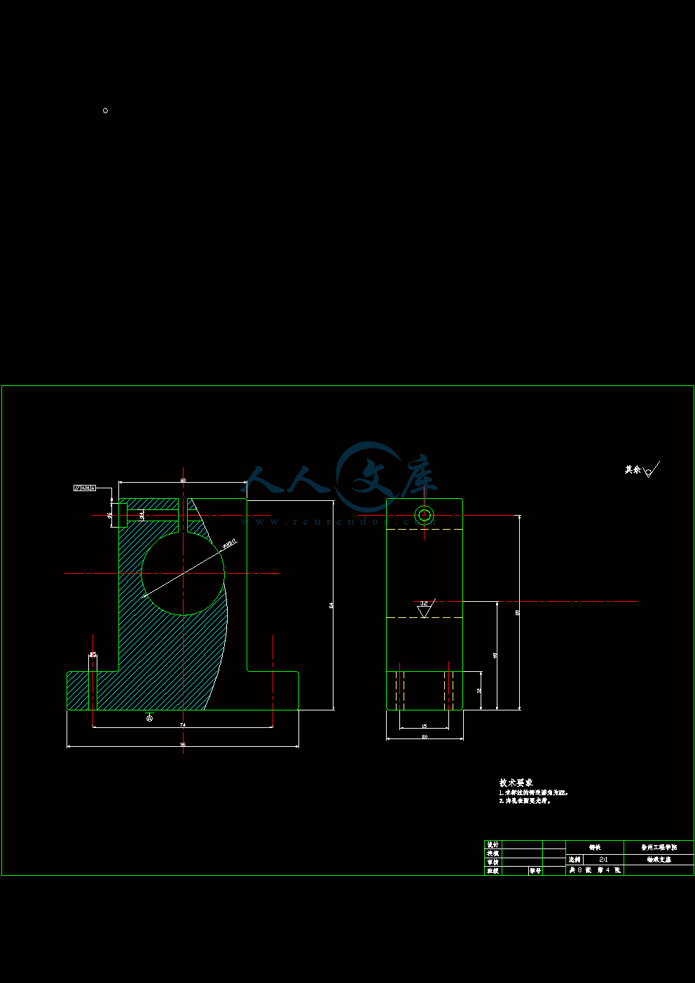
防尘盖(A3).dwg
防尘盖(A3).dwg

数控车床进给系统传动系统设计【8张图纸】【优秀】

收藏

压缩包内文档预览:
预览图
编号:423433    类型:共享资源    大小:1.64MB    格式:RAR    上传时间:2015-04-08 上传人:上*** IP属地:江苏
40
积分
关 键 词:
数控车床 进给系统 传动系统 设计 图纸 数控车床进给系统
资源描述:

数控车床进给系统传动系统设计

38页 22000字数+说明书+任务书+外文翻译+8张CAD图纸【详情如下】

A3轴承盖(A3).dwg

XY工作台设计图纸.dwg

主轴(A1).dwg

外文翻译--一个激光束加工(LBM方法)数据库的切割瓷砖  中文版.doc

外文翻译--一个激光束加工(LBM方法)数据库的切割瓷砖  英文版.pdf

拨块(A3).dwg

数控车床进给系统传动系统设计说明书.doc

滚珠丝杠副(A2).dwg

燕尾槽导轨(A1).dwg

论文.doc

轴承支座(A2).dwg

防尘盖(A3).dwg

目       录

摘 要I

AbstractII

1 绪论1

1.1 序言1

1.2设计主要任务2

2 进给系统设计3

2.1总体方案设计3

2.1.1 概述3

2.1.2 机械系统设计3

2.2 伺服电机设计5

2.2.1 伺服电机概述5

2.2.2 伺服电机选择6

2.3 滚珠丝杠副介绍10

2.3.1 滚珠丝杠副概述10

2.3.2 滚珠丝杠副特点11

2.3.3 滚珠丝杠副结构11

2.4 滚珠丝杠副设计12

2.4.1 设计滚珠丝杠副原理12

2.4.2滚珠丝杠副选择13

2.4.3 滚珠丝杠副预紧14

2.4.4滚珠丝杠副校核15

2.5 滚珠丝杠副密封与润滑17

2.6 滚轴丝杠副支撑选择及轴承选用18

2.6.1 支撑方式选择18

2.6.2 轴承选择19

2.6.3 轴承配合与润滑20

2.7 联轴器简介20

2.8 联轴器基本要求21

2.9 联轴器选择22

2.10 联轴器校核23

2.10.1 转矩校核23

2.10.2 销抗剪强度校核24

3 导轨设计25

3.1 导轨概述25

3.2 导轨分类25

3.3 导轨选型与长度计算25

3.4 导轨副技术要求26

3.5导轨的间隙调整27

4 防护罩设计29

4.1 基本要求29

4.2 选择设计29

4.3 其他设计30

4.3.1  基本要求30

4.3.2  支撑架设计31

总 结32

致 谢33

参考文献34

摘 要

   数控车床进给系统是指能分别沿着X 向和Y向做进给运动的系统,是许多机电一体化设备的基本部件,如数控车床的纵—横向进刀机构、数控铣床和数控钻床的X-Y工作台、激光加工设备的工作台、电子元件表面贴装设备等。模块化的X-Y数控工作台,通常由导轨座、移动滑块、工作、滚珠丝杠螺母副,以及伺服电动机等部件构成。其中伺服电动机做执行元件用来驱动滚珠丝杠,滚珠丝杠螺母带动滑块和工作平台在导轨上运动,完成工作台在X、Y方向的直线移动。导轨副、滚珠丝杠螺母副和伺服电动机等均以标准化,由专门厂家生产,设计时只需根据工作载荷选取即可。控制系统根据需要,可以选取用标准的工作控制计算机,也可以设计专用的微机控制系统。

   该设计从确定小型数控车床的方案入手,设计进给系统的装配图和主要零件图。确定数控车床数控系统后,详细论述进给传动系统各组成部分,以及各部分的计算和选用。

 关键词:数控车床; 进给系统; 装配图; 零件图

     数控车床进给系统的具体参数如下:

      X方向行程:100mm      

      Y方向行程:1500mm

        工作台面的参考尺寸:240260mm

        工作台和工件最大物重质量60kg

        工作台表面滑动摩擦系数为0.5

        平均切削力:500N

        快进进给速度:1000mm/min

        最高运动速度:10000mm/min

        脉冲当量0.001mm

        定位精度: 0.02mm

工作寿命:每天8小时,工作8年,250天/年

1 绪论

1.1 序言

数控技术是用数字信息对机械运动和工作过程进行控制的技术,是现代化工 业生产中一门新型的,发展十分迅速的高新技术。数控装备是以数控技术为代表 的新技术对传统制造业和新型制造业的渗透,形成的一种机电一体化技术。这一 技术使生产过程中的生产效率、产品成本及工人劳动强度等方面问题得以明显改 善,特别是针对对市场化生产的小批量、多品种特点,有无可比拟的优势。数控机床是采用了数控技术的机床。即能按照程序逻辑,一步步处理生产过程的机床。数控技术也叫计算机数控技术,目前它是采用计算机实现数字程序控制的技术。这种技术用计算机按事先存贮的控制程序来执行对设备的运动轨迹和外设的操作时序逻辑控制功能。由于采用计算机替代原先用硬件逻辑电路组成的数控装置,使输入操作指令的存贮、处理、运算、逻辑判断等各种控制机能的实现,均可通过计算机软件来完成,处理生成的微观指令传送给伺服驱动装置驱动电机或液压执行元件带动设备运行。

制造业是作为衡量一个国家经济的重要指标,体现了一个国家或一个民族的科技实力,是一个时代科学技术发展最明显的突出体现。尤其是在最近几十年了,发达的资本主义国际凭借其先进的制造技术,利用其强大的科技和财政实力获得了巨大的经济利益。我国的制造业起步晚、基础差,但近二十年来,我国投入了巨大的人力物力,并取得了骄人的成绩。但同时也要看到,我们国家的制造业和西方发达资本主义国家的制造业还有差距,而且在某种层度上说,差距还很大,这就要求我们国家还要付出更大的努力去提高我国的制造业在世界制造业中的地位,使我国的制造业对我国的经济发展能够发挥更大的作用,为人民和人类带来更大的帮助。

数控车床、车削中心,是一种高精度、高效率的自动化机床。配备多工位刀塔或动力刀塔,机床就具有广泛的加工艺性能,可加工直线圆柱、斜线圆柱、圆弧和各种螺纹、槽、蜗杆等复杂工件,可咨询:宁波众鑫数控机床厂。具有直线插补、圆弧插补各种补偿功能,并在复杂零件的批量生产中发挥 了良好的经济效果。传统的机械加工都是用手工操作普通机床作业的,加工时用手摇动机械刀具切削金属,靠眼睛用卡尺等工具测量产品的精度的。现代工业早已使用电脑数字化控制的机床进行作业了,数控机床可以按照技术人员事先编好的程序自动对任何产品和零部件直接进行加工了。数控加工广泛应用在所有机械加工的任何领域,更是模具加工的发展趋势和重要和必要的技术手段。

数控车床又称为 CNC车床,即计算机数字控制车床,是目前国内使用量最大,覆盖面最广的一种数控机床,约占数控机床总数的25%。数控机床是集机械、电气、液压、气动、微电子和信息等多项技术为一体的机电一体化产品。是机械制造设备中具有高精度、高效率、高自动化和高柔性化等优点的工作母机。控机床的技术水平高低及其在金属切削加工机床产量和总拥有量的百分比是衡量一个国家国民经济发展和工业制造整体水平的重要标志之一。数控车床是数控机床的主要品种之一,它在数控机床中占有非常重要的位置,几十年来一直受到世界各国的普遍重视并得到了迅速的发展。

1.2设计主要任务

进给系统机械传动结构是伺服进给系统的主要组成部分,主要由传动机构、运动变换机构、导向机构、执行件组成,它是实现成形加工运动所需的运动及动力的执行机构。由于数控机床的进给运动是数字控制的直接对象,被加工工件的最终位置精度和轮廓精度都与进给运动的传动精度、灵敏度和稳定性有关。进给系统是数控加工的关键环节,是数字控制的直接对象,被加工工件的最终坐标位置精度和轮廓精度都与传动结构有关。脉冲当量是0.001mm,快进速度是1000mm/min,X轴行程:100mm ,Y轴行程: 150mm。合理设计进给系统的结构;完成进给部件(包含滚珠丝杠螺母副、燕尾槽导轨、导轨防护罩等)的结构设计及总图和零件图;完成主传动系统的设计计算;完成二万字的毕业论文及5000字的译文。

内容简介:
中文译文一个激光束加工(LBM方法)数据库的切割瓷砖摘要 本文介绍了使用CO2laser切割机市售瓷砖切割,以期产生的激光束加工(LBM方法)数据库,其中包含其成功的关键参数信息对象处理。各种激光切割参数进行了研究,将产生一个瓷砖切割这需要最小的后处理。各种屏蔽气体多通切割和水下切割。 关键词:二氧化碳,激光切割,陶瓷材料,先进制造工艺1.介绍和背景 瓷砖切割手工方法非常类似于玻璃,即划线用钨硬质合金刀具材料的倾斜,由一个弯矩沿划线应用控制破裂之后开始。然而,手工技术仅限于直线切割和较大半径的削减。内部和削弱型材生产几乎是不可能单独与得分(与内部圈子可能例外),更复杂的方法将适用于有实现这些配置文件。传统上,金刚石锯片,流体力学(水射流)或超声波加工用于制造形状复杂的陶瓷砖,但这些过程是非常耗时和昂贵。例如,典型的钻石锯切割速度在20 mm每分最小 1的顺序,而氧化铝超声波钻孔每孔30 s需要2。 最关键的因子是二氧化碳激光切割瓷砖的使用所产生的裂缝损伤,基本上是在陶瓷基片内造成一个高温度梯度在切割过程。这些裂缝的强度,并减少对临界裂纹增长,这可能会导致部分或完全的瓷砖基板3故障源。因此,一个过程,减少诱发裂纹的形成是为现实的商业利用激光切割瓷砖最重要的。2 激光切割参数 任何材料激光加工都是是一个复杂的过程,涉及许多不同的参数,这都需要在配偶工作,生产优质的加工操作4,参数,如:(一)激光电源输入;(二)的重点设置;(三)协助气体种类和压力;(四)喷头配置;(五)工件厚度;(六)运动物理属性。在作者的部门此前的研究1,5,6也证明了在有效的激光切割上述参数临界。2.1激光功率激光功率取决于激光的类型。对于本文的工作报告,一费伦蒂数控激光切割机MF400受雇于,在400瓦特额定输出功率,但由于升级,束功率达到最大520和530间W的连续波(CW)切割模式。激光也有工作能力,在脉冲模式(PM)和超脉冲模式(SPM的,图1。)。为了确定在操作等效功率脉冲输出,脉冲功率图是在配合使用的下列基本方程: 图1 切割方法虽然激光切割机可经营50间和5000赫兹,500赫兹的频率被推荐的价值在以往的工作1,5。由于此设置被证明是成功的,只有到其他频率进行了有限度的调查(250赫兹,750和100赫兹)。2.2 切割速度 工作上用的数控激光切割机的费伦蒂MF400使用了10000mm每分钟最大进给速度。以前的工作6如上所述,饲料率6000mm每分钟一被证明是不稳定的标准化测试。最佳切割速度与功率设置,更重要的变化,随着工件的厚度。2.3 保护气体种类和压力 压缩空气,氩气,氮气和氧气被用来作为挡箭牌气体切割过程中,与P最大约等于4条。不同的屏蔽气体被用来检测处理后其对切割质量的影响,因为不仅保护气体冷却和切割边缘并移除熔融材料,但也产生与基体材料的化学反应7。这个化学反应的结果不同的保护气体为每个使用的类型。对于不同的测试目的磷含量在0.5至2.5巴的步骤,然后在步骤由2.6至0.2巴最大达到气体的压力。2.4 喷嘴配置 喷嘴直径直接有助于达到的最大气体压力,从而对气体的质量流速为切割经济学的重要,特别是使用氩气和氮气钢瓶。喷嘴出口的只有圆形剖面可用(0.6 毫米Ns20毫米),但这个统一的喷管的几何形状允许在任何方向切割。2.5 喷嘴高度和重点定位 在成立该喷嘴高度应依该联络点的地位激光切割机的费伦蒂MF400仅拥有(升级前原本是一个短46毫米焦距可)一个110毫米长焦距的长度,这可能是由正负5毫米改变。如果喷嘴高度被错误地设置梁将夹的喷嘴,减少功率输出相当于工件。对于大部分的检验重点高度设置,以便重点是在工作,即工件的顶面。这种情况显然管辖上述工件喷嘴的位置。3 实验过程 六硅类型:氧化铝基陶瓷砖进行了研究(表1),从不同的countries.Note的是,各种瓷砖组成,厚度一样起源,但都具有一个表面釉在7.5的情况下,8.6和9.2毫米西班牙瓷砖的釉层双层。3.1 设置程序由于是一个标准的测试条件的需要,实施下列程序测试开始前的:(一)验证,束功率为规范,即520-530 W于满功率(连续)开发的,虽然这下降到50瓦约1小时的测试;(二)喷嘴和焦镜头被检查,以确保其处于良好状态的,即清洁,完好;(三)保护气体的压力调节器和保护气体坦克被打开为了防止损坏的焦点镜头;(四)激光束中心内使用的喷嘴下午一广场测试,以较低的能源投入被用于切割低碳钢上,闪着火花的密度,从一个正方形切割产生被检查,看它是否是同样关注的淘汰线分布;及(五)的焦点是确定其所需的定位,即在工作。表1 使用瓷砖的类型3.2 测试 直线测试(SLT)的被用于评估全面通过切割(FTC)的激光参数的变量。角切割配置为探讨如何在紧张的几何材料切割反应。圆方检定测试和设计,确定了从切割各种几何形状的影响造成的。为两个独立的参数对一试件允许这个工作队的联合试验完成后,结果在场自动在切割矩阵中所形成的削减形式。 P和V是最重要的激光参数,因为它们决定了每单位的能源投入量的切割长度,因此他们对这个工作队配对,因为是P和Ns的管辖之盾气体的质量流量。 对于光伏测试运行时,功率保持不变,而切削速度增加沿切割恒定的切削长度切割速度,必须有足够的规模,以适应加速或减速的变化之间的数控表减速:以前的工作6指出,50毫米是足够的。解释结果是比较容易,因为它们表格形式,与切割矩阵清楚显示任何趋势或模式发生由于参数设置的变化。这个工作队还允许大量的削减进行了很短的时间框架了。这证明有利,因为激光往往随时间的漂移,从它的初始设置。必须采取预防措施,避免定位于从连续加热接近切割瓷砖作为一个瓦体温度的变化,由此产生的任何数据将无效。最初,削减20毫米之间,采用分离,这足以证明。为了研究如何关闭削减可能作出相互之间的切割分离,减少了2毫米递增,从最初的20毫米间距。在这个工作队的其他激光参数都必须保持不变6。对于P与五,f被500赫兹举行与NS1.2毫米和P三栏。光束焦点仍然在工作。从P结果:第V切割矩阵确定了切割速度固定值为后续SLT和脉冲设置。对于Ns:切割矩阵,沿喷嘴尺寸保持不变在X轴(参考图。2(一),而P的增加0.2杆2杆的步骤,在Y轴(切分离常数保持在20毫米)。新矩阵其后创建每个喷嘴的大小。角测试(图2(b)被用来研究如何切料反应持续曝光从期间的紧加工的激光束几何(即有几个削减在接近接近的除外)。测试中提到的接近为普通话机决定如何关闭平行线可切割给对方,而角测试是用来确定效果如何切割锐角切割质量。从一个角度切工件减少从4510,对应的表面光洁度质量(SFQ)指出。有两个原因进行平方和循环测试(图2(c)和(d):第一,确定对激光束引入优化方法内部切割型材;其次,以确定是否有是任何维度的大小限制方形或孔切。如果不能正确介绍,激光光束会导致内部切剖面在失败点介绍,由于短暂的,但过度从切削热梯度(即热诱导休克)。因此,利用光束介绍的方法,如穿孔,复杂到一个配置文件中启用几何形状进行调查。什么也成为明显的是在测试过程中的重要性梁位置提取轮廓和切割梁出发点的相对位置几何,即无论是在一个角落里或在直边。图2 测试配置 :(a);直线测试(b);角测试(c);循环测试(d); 方检定3.3 多通和水下切割多道切割是一个低功率(P=100瓦)的激光束开始。在第一阶段产生了良好的基体中定义的盲缝,接着由第二通过削减更深,等等。这个过程重复直到切口约20毫米深,然后激光功率为500瓦和切换到做最后的联邦贸易委员会。多通采伐的目的是要减少能源使用的投入少,每单位长度的热过载。在这个测试中使用的参数列于表2。 表2 多道切削参数 水下切割与目标进行降低周围地区的热切割的影响并还审议了关于通过切割质量的影响加快散热使用水8。陶瓷瓦划归水和喷嘴还浸在水中,防止保护气体压力任何进入水射流喷嘴室。4 切割质量材料特性,激光参数和工件几何均对最终结果产生重大影响激光切割工艺。本质特征是切割质量表面粗糙度和糟粕的高度,而裂纹长度决定了强度降低衬底(图3)。在整体SFQ釉表面被列为按规模分级列于表3。因此,对切割质量表面和边缘进行测量与尊重的:(一)表面粗糙度;(二)表面光洁度和;(三)糟粕坚持。 图3 用于激光切割瓷砖的质量标准 图4 Ra的测量切面4.1 表面粗糙度 重要的是要测量表面粗糙度为这使切割质量的同时要衡量从以往的工作中获取的值1和价值观其他录得制造工艺。由于大量的削减正使得有必要减少裁员数量进行分析。因此,与SFQ小于2没有测量被削减。 砍掉了边缘表面粗糙度的特点由条纹线形成的左侧切削过程Ra值测定从中心线的切缘(图4)。测量结果接管了12.5毫米的手写笔与导线截止2.5毫米,即价值采取了五种读在穿越,这保证了手写笔走超过合理数量的纹线。4.2 残渣 坚持渣直接影响了Ra值削减和能力,消除内部切割的几何形状。一微米是用来衡量在其糟粕高度三沿切节间隔。糟粕高度一直相当稳定(约1毫米)与所有类型的切割。由于此值被认为是没有实际意义,它不是记录在数据库。5 结果 表4包含目前雷射加工切割数据库这是从结果汇编瓷砖工作本文报道。第一部分表包含衬底参数和结果大气中削减,而水下的结果切列在第二部分。5.1 参数影响5.1.1 切割速度对于较薄的砖(ts7毫米)的P:第V切割矩阵显示与SFQ一联邦贸易委员会广泛的地区。在巴西的瓷砖案(3.7毫米的TS)联邦贸易委员会是获得的切割高达2200毫米的速度1分镨上下0.5(与减少的速度)在f500赫兹。这个地区在减少与增加瓷砖厚度,并与身体的颜色发红(一般的厚砖体颜色较深)。图5显示了最大切割速度为联邦贸易委员会随徘徊。在指数的关系得到同意与以前的工作6不同材料如钢材,木材和有机玻璃。切割矩阵还表明,一旦切割速度超过价值观为达到美国联邦贸易委员会,划线或盲目切割效果。 图5 Vmax随Ts的变化5.1.2 脉冲 脉冲为所有,但厚厚的西班牙瓷砖的激光是不是必须的,因为连续设置产生切断与一个良好的SFQ分级。在成功获得美国联邦贸易委员会公关巴西0.4瓦,但是如此之低的,在实际意义上,设置是不可行的。论梁厚脉冲西班牙瓷砖是必需的,连续引起了釉裂。这可能是由于输入的能量单位的切割长度超过热膨胀引起的热冲击率不同的釉料充分从父项瓦。由于激光脉冲的能量输入的减少约25瓦,每下降0.1在箴在f500赫兹,表面釉裂几乎消失在公关0.6和最佳的切割速度,虽然微小在切边仍然裂缝(的0.5毫米宽的顺序排列)仍然存在。5.1.3 气体压力 此参数对质量有很大影响,削减的速度,可以作出成功。以前的工作2已经表明,高瓦斯压力被要求实现厚基板(联邦贸易委员会的TS7毫米)。这证明了取得的成果在P:南北切割矩阵。高品质被削减在薄砖(tsB6毫米)实现在气体压力2个酒吧,但在双层玻璃,厚砖值SFQB3没有实现,除非p 3吧。在低压力(pB2.5栏),最大切割速度为联邦贸易委员会的大幅下降,当气体中的角色失败糟粕清晰。在连续下跌巴西瓷砖的Vmax从2200 mm最小的酒吧在P1到3.8分钟一1500毫米在P3条。在表面釉裂也增加成为在低气压明显。导致这结论是,保护气体为冷却剂的作用从而有助于最大限度地减少大热梯度创建的光束。5.1.4 气体种类 压缩空气为前面的推荐工作1证明了在适当的熔融材料去除其放热性能不受任何不利的影响以上的瓷砖厚度齐全。切割使用惰性气体氩气和氮气产生更好的结果,尤其是后者,因为它充当高效冷却剂9。与SFQ1高品质的削减生产了较厚的瓷砖在最佳的360毫米分钟1切削速度在CW模式。然而,当使用所需的高瓦斯压力,一缸氮气或氩气是用来迅速。5.1.5 喷嘴尺寸 这个参数直接关系到P(即喷嘴尺寸越小越高的索取压力)。表5显示了最大的实现盾与相应的喷嘴气体压力的大小当使用压缩空气。喷嘴直径大于1.5 mm的漠视Pmax的不足。直径较小的喷嘴产生更好削减较高的切削速度。5.1.6 联络点定位 在测试过程中梁的焦点仍在工作中,即表面上。切断与充足SFQ分级取得了与此设置。调查显示,通过降低进入的焦点工作的残渣残留降低,在提高焦点距离为失去工作的美国联邦贸易委员会梁德为重点。因此,基于实际理由,焦点仍然在工作。5.1.7 多道切割 厚瓦片被切断成功的多通法无切割质量退化。由于低功率激光束,温度梯度在瓦大大减少,从而物质损失减少到最低限度。这种方法也可以用来处理有任何骨折较厚的陶瓷。然而,多道切割已成为一个明显的劣势非常耗时的过程,并会证明不符合经济原则在商业基础上。5.2 实质影响 较深的体密度和瓷砖的重,他们保留在切割时比白人身体更热瓷砖。分析如何实施的切割是不可能的,因为瓷砖的厚度也增加身体的颜色变暗,在厚度增加掩盖对材料的成分任何效果。在瓷砖的材料组成部分并不相同。这是否是由于特定的瓷砖制造工艺是未知的,但结果削减联邦贸易委员会是一个损失的,即使在最佳切削速度。釉损害是在评估减少的重要因素质量。在所有,但厚釉砖损伤即使在最小的贫困参数设置。例如,用7.5毫米为最西班牙瓷砖SFQ53用压缩空气削减,虽然氮生产更好的价值。与此问题是后一种类型瓷砖有双层釉。没有出现开裂在较低的白色釉(类似于其他瓦),但上明确釉分裂和片状如在瓦能量输入或保暖性太高,巴贝罗,考夫曼和Idelsohn10所示釉的表面通常拥有不同的线性膨胀率到基础基板。因此,大温度梯度引起的激光光束会导致较低的基材,以扩大在不同的率,导致釉开裂。表3 最大压力(压缩空气)的不同喷嘴尺寸 另一个重要的因素是数量控制能量输入,并从削减散热。该参数设置效果不佳要么损失ofFTC(这是很容易地更正),或热休克瓷砖或表面釉(即在釉裂)。激光切割过程中容易推广热在切割冲击,因此这是至关重要的控制效应参数的正确选择。该瓷砖的热性质主要是造成这个问题的,一般有一个贫穷的瓦导热系数(0.9 W mk的15k51 W马可福音1)和相对较低的共同扩张效率(2 10 6K表15a5510 6 K表1)。 玻薄膜(或渣),涵盖的切缘增厚,在增加和减少瓷砖基板在切割速度。在糟粕增加,因为瓦厚度是显而易见的:更多的瓷砖融化,因此更糟粕的结果。该影片还厚度的糟粕通过多种多样的削减。有两个明显的原因这一点。 首先,梁宽分道扬镳后联络点(即在工作了),造成了外的平坦度的削减而导致在一个更大的缝宽度在底部。因此,更多的家长瓦降低材料熔化切割下来。根据对激光焦距和焦点定位点,切缝宽度不等的焦点尺寸(约0.1毫米)到2毫米。 第二,有能力或屏蔽气无力继续通过削减集中喷射也出于对切缘的糟粕格局。在顶削减那里的气体压力仍高,气还是针对流动,很少或没有糟粕的黏附显而易见,但由于切削深度增加气流变得更加动荡,减少压力,因此允许更多残渣切缘。Journal of Materials Processing Technology 84 (1998) 4755A laser beam machining (LBM) database for the cutting ofceramic tileI. Black *, S.A.J. Livingstone, K.L. ChuaDepartment of Mechanical and Chemical Engineering, Heriot-Watt Uni6ersity, Riccarton, Edinburgh EH14 4AS, UKReceived 13 December 1997AbstractThis paper covers the cutting of commercially-available ceramic tiles using a CO2laser cutting machine, with the object ofproducing a laser beam machining (LBM) database that contains the essential parameter information for their successfulprocessing. Various laser cutting parameters were investigated that would generate a cut in ceramic tile which required minimalpost-treatment. The effects of various shield gases, of multi-pass cutting and of underwater cutting were also examined. 1998Elsevier Science S.A. All rights reserved.Keywords:CO2; Laser cutting; Ceramic materials; Advanced manufacturing processes1. Introduction and backgroundManual methods of cutting ceramic tiles are verysimilar to that for glass, i.e. scribing the materials withtungsten-carbide tipped cutter, followed by the applica-tion of a bending moment along the scribed line toinitiate controlled fracture. However, manual tech-niques are limited to straight-line cutting and relativelylarge-radius cuts. Internal and undercut profiles arenearly impossible to produce with scoring alone (withthe possible exception of internal circles); more sophis-ticated methods having to be applied to achieve theseprofiles.Traditionally,diamond-saw,hydrodynamic(water jet) or ultrasonic machining are used to createcomplex geometries in ceramic tiles, but these processesare very time consuming and expensive. For example,typical diamond-saw cutting speeds are in the order of20 mm min11, while ultrasonic drilling of Al2O3takes over 30 s per hole 2.The most critical factor arising from use of a CO2laser to cut ceramic tiles is crack damage, which isessentially caused by a high temperature gradientwithin the ceramic substrate during the cutting process.These cracks reduce the strength and are sources forcritical crack growth, which may result in partial orcomplete failure of the tile substrate 3. Thus a reduc-tion of process-induced crack formation is paramountfor the realistic commercial use of lasers to cut ceramictiles.2. Laser cutting parametersLaser machining of any material is a complex processinvolving many different parameters that which all needto work in consort to produce a quality machiningoperation 4, parameters such as: (i) laser power input;(ii) focal setting; (iii) assist gas type and pressure;(iv) nozzle configuration; (v) workpiece thickness; and(vi) optophysical properties.Previous research within the authors department1,5,6 has also demonstrated the criticality of the aboveparameters in efficient laser cutting.2.1.Laser powerLaser power depends on the type of laser used. Forthe work reported in this paper, a Ferranti MF400CNC laser cutter was employed, rated at a poweroutput of 400 W. However, due to upgrading, themaximum beam power achievable was between 520 and* Correspondingauthor.Fax:+441314513129;e-mail:i.blackhw.ac.uk0924-0136/98/$ - see front matter 1998 Elsevier Science S.A. All rights reserved.PIIS0924-0136(98)00078-8I. Black et al./Journal of Materials Processing Technology84 (1998) 475548530 W in continuous wave (CW) cutting mode. Thelaser also had the ability to work in pulse mode (PM)and super-pulse mode (SPM; Fig. 1). To determine theequivalent power output during pulsing operation, apower verses pulsing chart was used in conjunctionwith the following basic equation 9:Pr=Pl/Psf=1/(Pl+Pr)Although the laser cutter could operate between fre-quencies of 50 and 5000 Hz, a value of 500 Hz wasrecommended in previous work 1,5. Since this settingproved to be successful, only limited investigation intoother frequencies was carried out (at 250 Hz, 750 and100 Hz).2.2.Cutting speedThe CNC table used with the Ferranti MF400 lasercutter had a maximum feed rate of 10000 mm min1.Previous work 6 indicated that feed rates above 6000mm min1proved to be unstable for any standardisedtesting. The optimum cutting speed varied with thepower setting and, more importantly, with the thicknessof the workpiece.2.3.Shield gas type and pressureCompressed air, argon, nitrogen and oxygen wereused as shield gases during cutting, with pmax:4 bar.Different shield gases were used to examined their effecton cut quality after processing, since the shield gas notonly cools and cut edges and removes molten material,but also generates a chemical reaction with the sub-strate material 7. The results of this chemical reactiondiffer for each type of shield gas used. For test purposesp was varied in steps of 0.5 bar from 1 to 2.5 bar, thenin steps of 0.2 bar from 2.6 bar to the maximumattainable gas pressure.2.4.Nozzle configurationThe nozzle diameter contributes directly to the maxi-mum achievable gas pressure and hence to the massflow rate of the gas was important for the economics ofcutting, especially when using cylinders of argon andnitrogen. Only circular profiles for the nozzle exits wereavailable (0.6 mm5Ns520 mm), but this uniformnozzle exit geometry allowed cutting in any direction.2.5.Nozzle height and focal positioningThe height at which the nozzle was set was governedby the position of the focal point. The Ferranti MF400laser cutter only possessed a long focal length of 110Fig. 1. Cutting modes.mm (originally a short focal length of 46 mm wasavailable before upgrading) and this length could bealtered by 95 mm. If the nozzle height was incorrectlyset the beam would clip the nozzle and reduce theequivalent power output to the workpiece 6. For thebulk of the testing the focal height was set so the focalpoint was on the job, i.e. on the top surface of theworkpiece. This condition obviously governed the posi-tion of the nozzle above the workpiece.3. Experimental procedureSix types of Si/Al2O3-based ceramic tiles were exam-ined (Table 1), originating from different countries.Note that the composition of the tiles varied, as did thethickness, but all possessed a surface glaze and in thecase of the 7.5, 8.6 and 9.2 mm Spanish tiles the glazewas double layered.3.1.Set-up procedureSince there was a need for standard testing condi-tions, the following procedure was implemented beforethe start of testing: (i) the beam power was validated tospecification, i.e. 520530 W developed at full power(CW), although this dropped to around 50 W afterTable 1Types of ceramic tile usedts(mm)Tile typeBody colour3.7BrazilianWhite4.7WhitePeruvianLight redItalian5.2SpanishRed5.74Spanish7.5RedRedSpanish8.69.2RedSpanishI. Black et al./Journal of Materials Processing Technology84 (1998) 475549about 1 h of testing; (ii) the nozzle and the focal lenswere checked to ensure that they were in good condi-tion, i.e. clean and undamaged; (iii) the shield gaspressure regulator and shield gas tanks were turned onto prevent damage to the focal lens; (iv) the laser beamwas centred within the nozzle using a square test, alower energy input in PM being used to cut a square ona mild steel, the sparking density that resulted fromcutting being checked to see if it was equally distributedabout the cut line; and (v) the focal point was set for itsdesired positioning, i.e. on the job.3.2.TestingA straight-line test (SLT) was used to evaluate thevariablelaserparametersforfullthrough-cutting(FTC). Angular cutting was configured to investigatehow the material reacted during cutting of tight geome-try. Circular testing and square testing were devised todetermine the effects resulting from cutting variousgeometries.The SLT allowed for the combined testing of twoseparate parameters on one testpiece, upon completionthe results being present automatically in a cuttingmatrix in the form of the resulting cuts. P and V arethe most important laser parameters, as they dictate theamount of energy input per unit length of cut, thereforethey were paired for the SLT, as were p and NSwhichgovern the mass flow rate of the shield gas.For the P/V test runs, the power was held constantwhile the cutting speed was increased along the cut(Fig. 2(a). The length of cut at constant cutting speedhad to be of sufficient magnitude to accommodate theacceleration or deceleration of the CNC table betweenfeed changes: previous work 6 indicated that 50 mmwas adequate. Interpreting the results was made easierdue to their tabular format, with the cutting matrixshowing clearly any trends or patterns occurring due tothe changes in parameter settings. The SLT also al-lowed a large number of cuts to be carried out over ashort time-frame. This proved advantageous, as thelaser tended to drift from its initial settings with time.Precautions had to taken to avoid localised heating inthe tile from continuous close proximity cutting, as achange in tile body temperature would invalidate anyresulting data. Initially, a 20 mm separation betweencuts was used and this proved sufficient. In order tostudy how close the cuts could be made to each other,the separation between cuts was reduced by incrementsof 2 mm from an initial 20 mm spacing.During the SLT the other laser parameters had to beheld constant 6. For P versus V, f was held at 500 Hzwith NS=1.2 mm and p=3 bar. The beam focal pointremained on the job. The results from the P/V cuttingmatrix determined the fixed values for the cutting speedand pulse settings for the succeeding SLT. For the NS/pFig. 2. Testing configuration: (a) straight-line testing; (b) angulartesting; (c) circular testing; (d) square testing.cutting matrix, the nozzle size remained constant alongthe x-axis (refer to Fig. 2(a) while p was increased insteps of 0.2 bar from 2 bar in the y-axis (the cutseparation remained constant at 20 mm). A new matrixwas created subsequently for each nozzle size.Angular testing (Fig. 2(b) was used to investigatehow the cut material reacted to sustained exposurefrom the laser beam during the machining of tightgeometries (i.e. where several cuts are made in closeproximity to each other). The proximity test mentionedfor SLT determines how close parallel lines can be cutto each other, whereas angular testing is used to deter-mine how the cutting of acute angles effects the cutquality. The angles cut from a workpiece were reducedfrom 45 to 10 and the corresponding surface finishquality (SFQ) was noted.I. Black et al./Journal of Materials Processing Technology84 (1998) 475550Table 2Multi-pass cutting parametersPlCutting modePsNo. of passesLast cutCW60FTC9000100SPMFTC100Table 3Grading of SFQGrading1No cracking in surface glaze, solid sharp cut edgeMinimal glaze cracking (WcB2 mm) with slight2loss of sharpness in cut edgeMedium cracking (2 mmBWcB4 mm) and slight3damage to unglazed tile substrateSignificant damage to glaze coating (Wc6 mm),4heavy damage to unglazed substrate causing flakingin the glazed surface5Same as 4 but with the formation of cracks in thetiles main body leading to structural failure in apart of the tile (usually at the end of a cut orwithin 8 mm of the tile edge).There are two reasons for conducting square andcircular testing (Fig. 2(c) and (d): first, to determinethe optimum method of laser-beam introduction tointernal cut profiles; and secondly, to determine if therewas any limitation in the dimension of the size ofsquare or hole cut. If not correctly introduced, the laserbeam would cause an internally-cut profile to fail at thepoint of introduction, due to the brief but excessivethermal gradient induced from cutting (i.e. thermalshock). Therefore, utilising methods of beam introduc-tion, such as trepanning, onto a profile enabled com-plex geometries to be investigated. What also becameapparent during testing was the importance of theposition of beam extraction from the cut profile and theposition of the beam starting point relative to thegeometry, i.e. whether it was at a corner or on astraight edge.3.3.Multi-pass and underwater cuttingMulti-pass cutting was begun with a low power(P=100 W) laser beam. The first pass produced a welldefined blind kerf in the substrate, followed by a secondpass to cut deeper and so on. The process was repeateduntil the kerf was about 20 mm deep and then the laserpower was switched to 500 W and do the final FTC.The objective of multi-pass cutting was to reduce ther-mal overload by use of less input energy per unitlength. The parameters used in this test are given inTable 2.Underwater cutting was conducted with the objectiveof reducing the influence of heat around the cut areaand also to examined the effect on cut quality throughaccelerated heat dissipation using water 8. The ce-ramic tile was placed under water and the nozzle wasalso dipped in water, the shield gas pressure preventingany water from entering the nozzle jet chamber.4. Cut qualityMaterial properties, laser parameters and workpiecegeometry have a significant effect on the final result ofthe laser cutting process. Cut quality is essentially char-acterisedbysurfaceroughnessanddrossheight,whereas crack length dictates the strength reduction inthe substrate (Fig. 3). The overall SFQ at the glazesurface was classified according to the grading scalegiven in Table 3. Therefore, the quality of the cutsurface and edge were measured with respected to:(i) surface roughness; (ii) surface finish and; (iii) drossadherence.Fig. 3. Quality criteria for the laser cutting of ceramic tiles.I. Black et al./Journal of Materials Processing Technology84 (1998) 475551Fig. 4. Measurement of Rafor the cut surface.4.1.Surface roughnessIt was important to measure surface roughness asthis allowed the cut quality to be gauged alongsidevalues obtained from previous work 1 and valuesrecorded for other manufacturing processes. Due to thelarge number of cuts being made it was necessary toreduce the number of cuts to be analysed. Thereforecuts with SFQB2 were not measured.The surface roughness of the cut edge was character-ised by the formation of striation lines left by thecutting process Ravalues were measured from thecentre-line of the cut edge (Fig. 4). Measurements weretaken over a 12.5 mm traverse of the stylus with acut-off value of 2.5 mm, i.e. five readings were takenover the traverse, which ensured that the stylus trav-elled over a reasonable number of striation lines.4.2.Dross adherenceDross adherence directly effected the Ravalue of thecut and the ability to remove internally-cut geometries.A micrometer was used to measure the dross height atthree intervals along the cut section. The dross heightremained fairly constant (approximately 1 mm) with alltypes of cutting. Since this value was deemed to be ofno practical importance, it was not recorded in thedatabase.5. ResultsTable 4 contains the current LBM database for cut-ting ceramic tiles that was compiled from the results ofthe work reported in this paper. The first part of thetable contains the parameters and results for substratescut in atmosphere, while the results for underwatercutting are shown in the second part.5.1.Parameter effects5.1.1.Cutting speedFor the thinner tiles (tsB7 mm) the P/V cuttingmatrix showed a wide region of FTC with SFQ=1. Inthe case of the Brazilian tile (ts=3.7 mm) FTC wasobtained with cutting speeds of up to 2200 mm min1and down to Pr=0.5 (with reduced speeds) at f=500Hz. This region diminished with the increase in tilethickness and also with the redness of the body colour(generally the thicker tiles are darker in body colour).Fig. 5 shows how the maximum cutting speed for FTCvaries with ts. The exponential relationship obtainedconcurs with previous work 6 for different materialssuch as steel, wood and perspex. The cutting matrixalso showed that once the cutting speed exceeded valuesfor attainable FTC, scribing or blind cutting results.5.1.2.PulsingPulsing the laser for all but the thick Spanish tileswas not required, as the CW setting produced cuts witha good SFQ grading. Successful FTC was obtained atPr0.4 in the Brazilian tile, but Vmaxwas so low that,in a practical sense, the settings were not viable. On thethick Spanish tiles pulsing of the beam was required, asCW caused cracking in the glaze. This was probablydue to an excess of energy input per unit length of cutcausing thermal shock as the thermal expansion rate ofthe glaze differed sufficiently from that of the parenttile. Since pulsing the laser reduced the energy input byapproximately 25 W for every 0.1 drop in Pr at f=500Hz, the surface glaze cracking virtually disappeared atPr=0.6 and optimum cutting speed, although tinycracks (of the order of 0.5 mm wide) at the cut edge stillremained.5.1.3.Gas pressureThis parameter has a great effect on the quality andthe rate at which cuts could be made successfully.Previous work 2 had shown that high gas pressureswere required to achieve FTC on thick substrates (ts7 mm). This was borne out by the results obtained fromthep/Nscuttingmatrix.Highqualitycutswereachieved in the thinner tiles (tsB6 mm) at gas pressuresof 2 bar but in the double-glazed, thicker tiles values ofSFQB3 were not achieved unless p3 bar. At lowpressures (pB2.5 bar), the maximum cutting speeds forFTC dropped drastically, as the gas failed in its role ofdross clearer. Vmaxfor Brazilian tile in CW droppedfrom 2200 mm min1at p=3.8 bar to 1500 mm min1at p=3 bar. An increase in surface-glaze cracking alsobecame apparent at low gas pressures. This led to theconclusion that the shield gas was acting as a coolantand thus helping to minimise the large thermal gradientcreated by the beam.I. Black et al./Journal of Materials Processing Technology84 (1998) 475552Table 44 LBM database for ceramic tilesAtmospheric cuttingRa(mm)V (mm/min)Tile typets(mm)BodyShield gasSFQGlaze typeNs(mm)Geometricp (bar)Pl-Pscutcolour1.21.51Brazilian3.7WhiteWhiteStraightCW5001000C. air32535253511.21.53180205001000C. air31.21.51253516040500900C. air253511.21.53Internal18020400600C. air1.21.515Angular16040300500C. air32535253511.21.53Radial18020300500C. air31.21.51Peruvian4.72535WhiteWhiteStraightCW500700C. air125351.21.5318020500700C. air31.21.51253516040500700C. air253511.21.53Internal18020300500C. air31.21.5152535Angular16040250450C. air125351.21.53Radial18020250450C. air31.21.51Italian5.21725Light redWhiteStraightCW500700C. air1.21.5118020500700C. air3172511.21.51725316040500700C. air1.21.51Internal18020300500C. air317251725151.21.53Angular16040200400C. air31.21.511725Radial18020200400C. air203011.21.5Spanish5.74Red3WhiteStraightCW300550C. air1.21.5118020300400C. air32030203011.21.5316040300450C. air31.21.512030Internal18020200350C. air2520301.21.53Angular16040200300C. air31.21.512030Radial18020200350C. air163721.21.5Spanish7.5Red3Clear/whiteStraightCW200370C. air31.21.52163718020200350C. air1637121.21.5316040200350C. air31.21.52163714060200350C. air1.21.512Internal14060200300C. air31637351.21.516373Angular14060200250C. air1.21.513Radial16040200300C. air3163791211.2Spanish8.5Red2.8WhiteStraight1002503070Argon2.81.219111002003080Argon121311.22.81003003040Argon1.211502503080Argon2.8101411.22.8Internal1002007080Argon2.81.211502505070Argon31.21.52.2StraightCW150250Argon2.21.21.534618020150250Argon48241.21.52.218030150250Argon2.21.21.5246918040150250Argon247111.21.52.218050150250Argon2.21.21.5391116020150250Argon1.21.5316030150250Argon2.2101131.21.511132.216040150250Argon1.21.5214020150200Argon2.21012101431.21.52.214040150200Argon2.21.21.53101414060150200Argon7911.2Spanish8.5Red3.5WhiteStraight15025050C. air3.51.21100250783050C. air101211.23.51002005070C. air3.51.212Angular1002006080C. air315181.23.5StraightCW70160Nitrogen3.51.219121502504060Nitrogen81011.23.51002503050NitrogenNitrogen3.51.219111002002050I. Black et al./Journal of Materials Processing Technology84 (1998) 475553Table 4 (continued).Atmospheric cuttingts(mm)Tile typeBodyGlaze typeGeometricRa(mm)Pl-PsV (mm/min)Shield gasp (bar)Ns(mm)SFQcutcolourAngular1502504060Nitrogen3.51.2341002503040Nitrogen3.51.234StraightCW80100Oxygen3.51.231002005060Oxygen3.51.2110111002503050Oxygen3.51.219111502503080Oxygen3.51.211012Angular1502507080Oxygen3.51.213100-25050Oxygen3.51.213RedWhiteStraight15020040100SpanishC. air9.23.51.2110131002003040C. air3.51.219101002502030C. air3.51.21101215025030100C. air3.51.211012Angular1502004080C. air3.51.2141002003040C. air3.51.2141002502030C. air3.51.2141502504080C. air3.51.214Underwater CuttingRedWhite10 acute100-200508.5OxygenSpanish3.51.212100-25050Oxygen3.51.21215025050Oxygen3.51.212RedWhite10 acute100-20050OxygenSpanish3.59.21.21210025050Oxygen3.51.21215025050Oxygen3.51.212Note: focal point on the job; data for angular cut only.5.1.4.Gas typeCompressed air as recommended by previous work1 proved adequate in the removal of molten materialwithout any adverse effects from its exothermic proper-ties, over the full range of tile thicknesses. Cutting usingthe inert gases argon and nitrogen produced betterresults, especially with the latter as it acted as anefficient coolant 9. High-quality cuts with SFQ=1were produced in the thicker tiles at an optimum cut-ting speed of 360 mm min1in CW mode. However,when using the required high gas pressures, a cylinderof nitrogen or argon was used quickly.5.1.5.Nozzle sizeThis parameter was related directly to p (i.e. thesmaller is the nozzle size the higher is the obtainablepressure). Table 5 shows the maximum achievableshield gas pressure with the corresponding nozzle sizeswhen using compressed air. Nozzles with diametersgreater than 1.5 mm were ignored as pmaxwas insuffi-cient. The smaller nozzle diameters produced bettercuts with higher cutting speeds.5.1.6.Focal point positioningDuring testing the focal point of the beam remainedon the job, i.e. on the surface. Cuts with an adequateSFQ grading were achieved with this setting. Investiga-tion showed that by lowering the focal point into thejob the dross adherence decreased and in raising thefocal point away from the job FTC was lost as thebeam de-focused. Therefore, for practical reasons, thefocal point remained on the job.5.1.7.Multi-pass cuttingThicker tiles were cut successfully by the multi-passmethod without degradation of cut quality. Due to thelow power of the laser beam, the temperature gradientin the tile was greatly reduced, thus material damagewas minimised. This method can also be used to pro-cess thicker ceramics without any fracture. However,multi-pass cutting has a distinct disadvantage in being avery time-consuming process and would prove uneco-nomic on a commercial basis.5.2.Material effectsThe darker-bodied tiles were denser and heavier andduring cutting they retained more heat than the white-body tiles. Analysing how this effected the cutting wasnot possible, as the thickness of tile also increased withdarkening of the body colour, the increase in thicknessmasking any of the compositional effects of the mate-rial. In some of the tiles the material composition wasnot homogeneous. Whether this was due to the specificI. Black et al./Journal of Materials Processing Technology84 (1998) 475554Fig. 5. Vmaxagainst tsfor ceramic tiles of different origin.tile manufacturing processes is unknown, but the resultson cutting were a loss of FTC even at optimum cuttingspeed.Glaze damage was a significant factor in assessing cutquality. In all but the thicker tiles glaze damage wasminimal even at poor parameter settings. For example,with the 7.5 mm Spanish tile SFQ53 for most of thecuts with compressed air, although nitrogen producedbetter values. The problem with this latter type was thatthe tile had a double-layered glaze. No cracking ap-peared in the lower white glaze (similar to the othertiles) but the upper clear glaze splintered and flaked ifthe energy input or heat retention in the tile was toohigh. Barbero, Kaufman and Idelsohn 10 have shownthat the surface glaze usually possesses a different linearexpansion rate to that of the underlying substrate.Therefore the large thermal gradient caused by the laserbeam causes the lower substrate to expand at a differ-ent rate, resulting in cracking of the glaze.Another significant factor was control of the amountof energy input and heat dispersion from the cut. Theeffects of poor parameter settings were either loss ofFTC (which was corrected easily), or thermal shock inthe tile or the surface glaze (i.e. cracking in the glaze).The laser cutting process readily promoted thermalshock during cutting, so it was vital to control thiseffect with the correct selection of parameters. Thethermal properties of ceramic tile were primarily thecause of the problem, as generally a tile has a poorthermal conductivity (0.9 W mK15k51 W mK1)and a relatively low co-efficient of expansion (2106K15a55106K1).The glassy film (or dross) that covered the cut edgethick
温馨提示:
1: 本站所有资源如无特殊说明,都需要本地电脑安装OFFICE2007和PDF阅读器。图纸软件为CAD,CAXA,PROE,UG,SolidWorks等.压缩文件请下载最新的WinRAR软件解压。
2: 本站的文档不包含任何第三方提供的附件图纸等,如果需要附件,请联系上传者。文件的所有权益归上传用户所有。
3.本站RAR压缩包中若带图纸,网页内容里面会有图纸预览,若没有图纸预览就没有图纸。
4. 未经权益所有人同意不得将文件中的内容挪作商业或盈利用途。
5. 人人文库网仅提供信息存储空间,仅对用户上传内容的表现方式做保护处理,对用户上传分享的文档内容本身不做任何修改或编辑,并不能对任何下载内容负责。
6. 下载文件中如有侵权或不适当内容,请与我们联系,我们立即纠正。
7. 本站不保证下载资源的准确性、安全性和完整性, 同时也不承担用户因使用这些下载资源对自己和他人造成任何形式的伤害或损失。
提示  人人文库网所有资源均是用户自行上传分享,仅供网友学习交流,未经上传用户书面授权,请勿作他用。
关于本文
本文标题:数控车床进给系统传动系统设计【8张图纸】【优秀】
链接地址:https://www.renrendoc.com/p-423433.html

官方联系方式

2:不支持迅雷下载,请使用浏览器下载   
3:不支持QQ浏览器下载,请用其他浏览器   
4:下载后的文档和图纸-无水印   
5:文档经过压缩,下载后原文更清晰   
关于我们 - 网站声明 - 网站地图 - 资源地图 - 友情链接 - 网站客服 - 联系我们

网站客服QQ:2881952447     

copyright@ 2020-2024  renrendoc.com 人人文库版权所有   联系电话:400-852-1180

备案号:蜀ICP备2022000484号-2       经营许可证: 川B2-20220663       公网安备川公网安备: 51019002004831号

本站为文档C2C交易模式,即用户上传的文档直接被用户下载,本站只是中间服务平台,本站所有文档下载所得的收益归上传人(含作者)所有。人人文库网仅提供信息存储空间,仅对用户上传内容的表现方式做保护处理,对上载内容本身不做任何修改或编辑。若文档所含内容侵犯了您的版权或隐私,请立即通知人人文库网,我们立即给予删除!