摘要
从塑料材料的性能分析,根据塑件的基本形状和尺寸入手,合理选择注射的成型方法。通过对塑件工艺性的分析和对模具生产条件及制造水平的掌握。开始进行模具的结构设计。其中模具的结构设计过程包括:型腔的数目和位置的确定,模具的总体结构形式设计,动模及定模成形零件尺寸的确定,浇注系统形式及尺寸的确定,脱模方式的确定,调温及排气系统的确定,模具结构各部分完成以后,便开始绘制模具的结构草图,根据具体尺寸校核注射模具及注射机的有关尺寸,并对工艺参数进行核定和计算。之后进行初步的审查对所存在的问题进行确定和修正,然后绘制模具总装配图,按装配图绘制成型零件及所有需要加工的零件工作图,同时考虑零件的加工工艺。
关键字:成型工艺;结构设计;试模
Abstract
From the plastic material performance analysis, according to models a basic shape and the size obtain, reasonably selects the injection to take shape the method. Though to models a technological analysis and to the mold working condition and manufacture level grasping, formulates the formed craft card. In formulates after the formed craft card, starts to carry on the mold the structural design. Mold structural design process includes. The cavity number and the position determination, the mold overall structural style design, moves the mold and decides the mold forming components size the determination ,pours the system andthe size determination, the drawing of PA66tterns mode determination after, adjusts warm and the exchaust gas completes, then starts to draw up the mold the structure schematic diagram, according to the specific size examination injection mold and the injection computer relatedsize, and carries on the checking and the computation to the craft PA66rameter. Carries on the determination and the revision afterward, then the plan mold assembly drawing, takes shape the components and all needs to process, simultaneously considers the components the processing craft.
Keyword: takes shape the craft; the structural design.
目录
摘要 2
Abstract 3
目录 V
前言 1
第二章 塑件的分析 3
2.1 塑件结构分析 3
2.1.1 塑件及塑件材料的特点 3
2.1.2 影响塑件尺寸精度的因素 4
2.2 塑件材料的选择与工艺性分析 5
2.2.1 工艺性分析 5
2.2.2 材料的选择 5
2.2.4 PA66的注射成型工艺参数 6
2.3 塑料成型工艺的种类 7
2.3.1 注射成型 7
2.3.2 压缩成型 7
2.3.3 压住成型 7
2.3.4 挤出成型 8
第三章 注塑机的选择与校核 9
3.1 注塑机的选择 9
3.1.1 由公称注射量选定注射机 9
3.1.2 由锁模力选定注射机 9
3.2 注塑机的校核 10
3.2.1 型腔数目的确定及校核 10
3.2.2 锁模力的校核 10
3.2.3 开模行程的校核 11
第四章 浇注系统 12
4.1 分型面的确定 12
4.1.1 分型面的选择原则 12
4.1.2 分型面的决定 13
4.2 浇注系统的定义 13
4.3 主流道的设计 14
4.4 分流道的设计 15
4.5 拉料杆与冷料穴的设计 16
4.6 浇口的设计 16
4.7 浇注系统的计算 18
4.7.1 剪切速率的校核 18
4.7.2 主流道剪切速率校核 18
4.7.3 浇口剪切速率的校核 18
4.8 排溢系统设计 19
第五章 成型零件设计 20
5.1 凹模的工作尺寸计算 20
5.2 型腔壁厚、支撑板厚度的确定 20
第六章 顶出系统 23
6.1 模具对脱模机构的要求 23
6.2 脱模力的计算 23
6.3 顶管的设计 25
第七章 温度系统 27
7.1 温度调节对塑件质量的影响 27
7.2 冷却系统的设计 28
7.2.1 冷却系统的设计原则 28
7.2.2 冷却回路的确定 28
7.3 冷却系统的计算 28
第八章 导向系统 32
8.1 导柱的设计 32
8.2 导向孔与导套 33
8.3 导柱的数量和布置 33
第九章 抽芯系统设计 35
9.1 侧向分型与抽芯机构的分类 35
9.2 侧向分型与抽芯机构的设计 36
第十章 模具开合模动作过程 38
总结与展望 39
参考文献 40
致谢 41
附录 42
①产品网格划分 42
②浇注系统的设计 43
③注塑工艺参数的设定 44
④ 模拟结果分析 45
前言
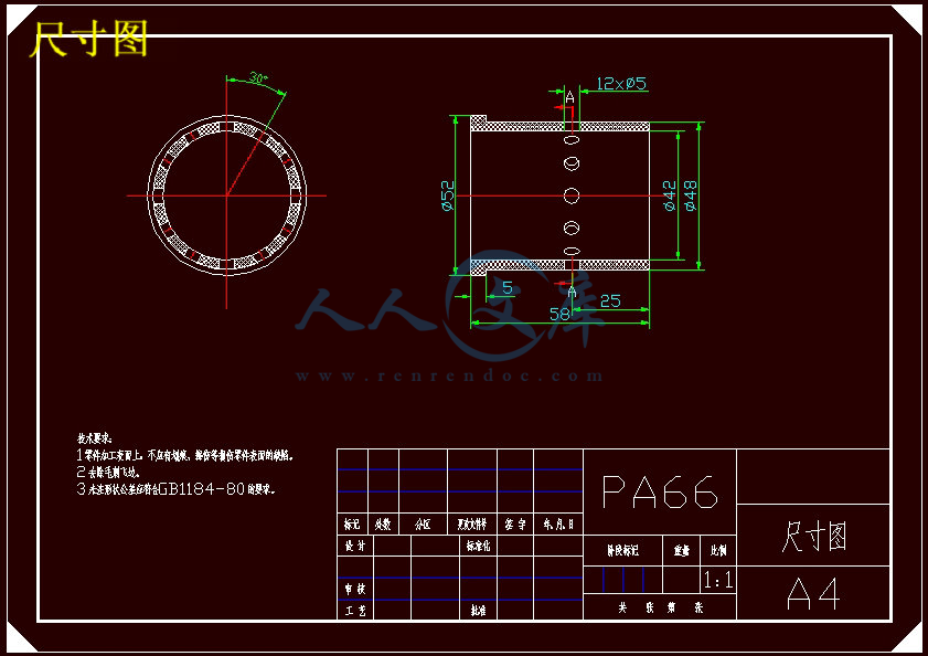
本文以分油套为对象,详细介绍其注射模设计过程。设计中主要用PRO/ENGINEER软件,根据制件的零件图进行零件的三维造型,采用模具专家系统EMX,提高了设计效率。通过Autocad完成工程图的制作,从塑料材料的性能分析,根据塑件的基本形状和尺寸入手,合理选择注射的成型方法。根据注塑的额定注塑量我们可以确定模具的型腔为一模一腔,制件圆周方向有12个侧孔,无法直接脱模,所以我们需要设计侧抽芯机构,利用转盘带动滑块来同时完成12个侧孔的抽芯,最后当主流道余料全部被拉出后,再利用推杆推出机构完成塑件的推出。
需要分析的问题是:塑料在型腔内的注射过程中流动情况,温度压力变化情况、注塑件残余应力等, 根据分析检查模具结构、流动状态、产品质量等问题。如是否存在浇注系统不合理, 流道和浇口位置尺寸是否不当, 型腔平衡以及产品的翘曲变形等。设计完成后,最后通过Autocad完成工程图的制作。


 川公网安备: 51019002004831号