Design_and_Simulation_of_Plastic_Injection_Moulding_Process.pdf

连接器壳体塑料注塑模具设计【20张CAD图纸和说明书】

收藏

压缩包内文档预览:
预览图 预览图 预览图 预览图 预览图 预览图 预览图 预览图 预览图 预览图 预览图 预览图 预览图
编号:10109126    类型:共享资源    大小:4.50MB    格式:RAR    上传时间:2018-05-17 上传人:俊****计 IP属地:江苏
40
积分
关 键 词:
连接器 壳体 塑料 注塑 模具设计 20 cad 图纸 以及 说明书 仿单
资源描述:

摘  要

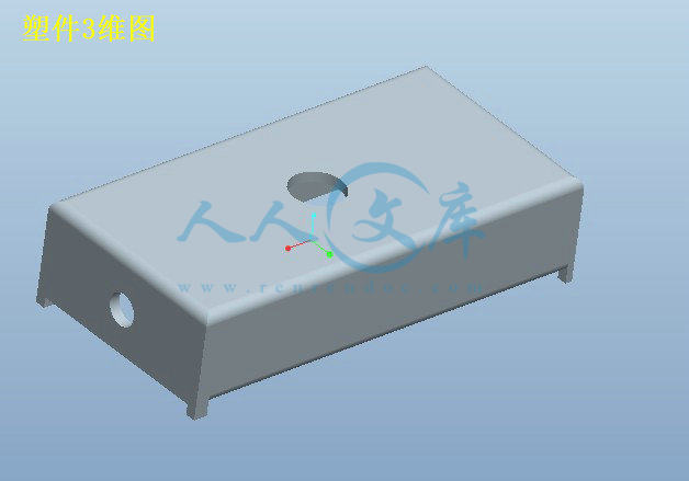
本文是关于连接器壳体塑料注塑模具的设计,通过正确分析塑件工艺特点和ABS材料的性能后,最终设计出一副注塑模。塑料制品具有原料来源丰富,价格低廉,性能优良等特点。它在电脑、手机、汽车、电机、电器、仪器仪表、家电和通讯产品制造中具有不可替代的作用,应用极其广泛。注射成形是成形热塑件的主要方法,因此应用范围很广。

注射成形是把塑料原料放入料筒中经过加热熔化,使之成为高黏度的流体,用柱塞或螺杆作为加压工具,使熔体通过喷嘴以较高压力注入模具的型腔中,经过冷却、凝固阶段,而后从模具中脱出,成为塑料制品。

本文详细介绍了模具的浇注系统、模具成型部分结构、顶出系统、冷却系统、注塑机的选择及有关参数的校核等等设计。运用CAD、辅助工程PRO/E等不同的软件分别对模具的设计、制造和产品质量进行分析。连接器壳体塑料注塑模具设计,采用一般精度,利用CAD、PRO/E来设计或分析注射模的成型零部件,浇注系统,导向部件和脱模机构等等。针对连接器的具体结构,该模具采用点浇口双分型面注射模具。由于塑件内侧有小孔,需要设置斜导柱。通过模具设计表明该模具能达到连接器的质量和加工工艺要求。综合运用了专业基础、专业课知识设计,其核心知识是塑料成型模具、材料成型技术基础、机械设计、塑料成型工艺、模具CAD\CAM等。


关键词:连接器壳体;注塑模具;CAD;PRO/E


The connector shell plastic injection mold design

Abstract

    This article is about the connector shell plastic injection mold design, through the technological characteristics of plastics article of correct analysis and the performance of ABS material, the final design out a pair of injection mold. Plastic products have rich raw material sources, low price, good performance, etc. It in computers, cell phones, cars, motors, electrical appliances, instruments and meters, household appliances and communications products manufacturing has irreplaceable function, is widely applied. Injection molding is the main method of forming thermoplastic parts, so the application range is very wide.

    Injection molding is melt the plastic raw material into the cylinder through the heating, made of high viscosity fluid, pressurized with piston or screw as a tool, makes the melt through the nozzle at high pressure into mold cavity, after cooling and solidification stage, and then out of the mould, plastic products.

Mould gating system are introduced in detail in this paper, the structure of the molding part, ejector system, cooling system, selection of injection molding machine and related parameters of checking, etc. Design. Using PRO/E CAD, auxiliary engineering such as different software respectively to the mold design, manufacturing and product quality are analyzed. Connector shell plastic injection mold design, using the general accuracy and the use of CAD, PRO/E to design or analysis of forming parts of injection mould, pouring system, guide parts and demoulding mechanism, and so on. According to the specific structure of the connector, the mould adopts the point gate double parting surface injection mould. Because there are holes plastic parts inside, need to set up the inclined guide pillar. Through the mold design shows that the mould can achieve connector quality and processing technology. Integrated use of the professional basis, professional class knowledge is designed, its core knowledge is the plastic molding mold, material molding technology base, mechanical design, plastic molding process, mould CAD/CAM, etc

.

Key words: the connector shell; Injection mould; CAD; PRO/E


目  录

1 绪论 1

1.1前言 1

1.2模具发展现状及发展方向 1

1.2.1国内外注塑模具的发展现状 1

1.2.2国内外注塑模具的发展趋向 3

1.3本课题的内容和具体要求 3

1.3.1本课题的内容 3

1.3.2具体要求 3

2 零件材料分析及方案论证 4

2.1零件的材料及材料的特性 4

2.1.1零件的材料 4

2.1.2 ABS材料的特点 4

2.1.3 ABS注射成型工艺参数 5

2.2 ABS注射成型的原理及工艺过程 5

2.2.1注射成型的原理 5

2.3注射模具的基本组成 6

2.3.1基本组成 6

3 注射成型机的选择与成型腔数的确定 7

3.1注射成型机的选择 7

3.1.1估算零件体积 7

3.1.2估算零件的质量 8

3.2锁模力 8

3.3选择注射机型号及注射机的主要参数 8

3.3.1注塑成型工艺简介注塑机的初步选择 8

3.3.2注塑成型工艺条件 9

3.3.3注塑机的初步选择 10

3.3.4 XS-ZY-125型注塑机的主要参数如下 10

3.4注塑机的校核 10

3.5成型腔数的确定 12

4 浇注系统的设计 13

4.1浇注系统的作用 13

4.2浇注系统的组成 13

4.3主流道设计 13

4.4分流道设计 15

4.5浇口设计 16

5 成型零件结构设计 17

5.1分型面的设计 17

  5.1.1分型面选择原则 17

5.2型腔的分布 17

5.3凹模的结构设计 17

5.4凸模的结构设计 17

5.5成型零件工作尺寸的计算 18

5.5.1影响塑件尺寸精度的因素 18

5.5.2模具成型零件的工作尺寸计算 18

5.6动模板的强度校核 19

5.6.1厚度计算 19

6 导向与脱模机构的设计 20

6.1导向机构的作用和设计原则 20

6.1.1导向机构的作用 20

6.1.2导向机构的设计原则 20

6.2导柱、导套的设计 20

6.2.1导柱的设计 20

6.2.2导套的设计 21

6.2.3导向孔的总体布局 22

6.3脱模机构的确定 22

6.4推杆横截面直径的确定与校核 22

6.4.1推杆横截面直径的确定 22

6.4.2推杆横截面直径的校核 22

6.4.3顶杆的形式 23

6.5复位杆的结构设计 24

6.5.1复位杆的作用 24

6.5.2的结构 24

6.6锁紧块 24

6.6.1锁紧块的作用 24

6.6.2锁紧块的设计 25

6.6.3锁紧块的结构形式 25

6.6.4锁紧块的具体结构形式 25

7 侧向分型与抽芯机构的设计 26

7.1斜导柱抽芯机构设计原则 26

7.2抽芯机构的确定 26

7.3斜导柱抽芯机构的有关参数计算 26

7.3.1抽芯距S 26

7.3.2斜导柱倾斜角α的确定 27

7.3.3斜导柱直径的确定 28

7.3.4斜导柱长度的计算 28

7.4滑块的设计 29

7.5导滑槽的设计 30

7.6滑块定位装置 31

7.6.1作用 31

7.6.2结构形式 31

8 成型零件尺寸计算 32

9 冷却系统 33

9.1温度调节对塑件质量的影响 33

9.2对温度调节系统的要求 33

9.3模具冷却装置的设计 33

9.3.1冷却装置的设计要点 33

9.3.2水嘴的结构形式 33

9.3.3冷却水道的结构 34

10 模具的可行性分析 35

10.1本模具的特点 35

10.2市场前景与经济效益分析 35

结论 36

参考文献 37

致 谢 38

毕业设计(论文)知识产权声明 39

毕业设计(论文)独创性声明 40


1 绪论

1.1前言

模具是利用其特定形状去成型具有一定的形状和尺寸制品的工具。 在各种材料加工工业中广泛的使用着各种模具。例如金属铸造成型使用的砂型或压铸模具、金属压力加工使用的锻压模具、冷压模具等各种模具。

对模具的全面要求是:能生产出在尺寸精度、外观、物理性能等各方面都满足使用要求的公有制制品。以模具使用的角度,要求高效率、自动化操作简便;从模具制造的角度,要求结构合理、制造容易、成本低廉。

    模具影响着制品的质量。首先,模具型腔的形状、尺寸、表面光洁度、分型面、进浇口和排气槽位置以及脱模方式等对制件的尺寸精度和形状精度以及制件的物理性能、机械性能、电性能、内应力大小、各同向性、外观质量、表面光洁度、气泡、凹痕、烧焦、银纹等都有十分重要的影响。其次,在加工过程中,模具结构对操作难易程度影响很大。在大批量生产塑料制品时,应尽量减少开模、合模的过程和取制件过程中的手工劳动,为此常采用自动开合模自动顶出机构,在全自动生产时还要保证制品能自动从模具中脱落。另外模具对制品的成本也有影响。当批量不大时,模具的费用在制件上的成本所占的比例将会很大,这时应尽可能的采用结构合理而简单的模具,以降低成本。

现代生产中,合理的加工工艺、高效的设备、先进的模具是必不可少的三项重要因素,尤其是模具对实现材料加工工艺要求、塑料制件的使用要求和造型设计起着重要的作用。高效的全自动设备也只有装上能自动化生产的模具才有可能发挥其作用,产品的生产和更新都是以模具的制造和更新为前提的。由于制件品种和产量需求很大,对模具也提出了越来越高的要求。因此促进模具的不断向前发展。

1.2模具发展现状及发展方向

1.2.1国内外注塑模具的发展现状

近年来我国的模具技术有了很大的发展,在大型模具方面,已能生产大屏彩电注塑模具、大容量洗衣机全套塑料模具以及汽车保险杠和整体仪表板等塑料模具。机密塑料模具方面,已能生产照相机塑料件模具、多型腔小模数齿轮模具及塑封模具。

在成型工艺方面,多材质塑料成行模、高效多色注塑模、镶件互换结构和抽

芯脱模机构的创新业取得了较大进展。气体辅助注射成形技术的使用更趋成熟。热流道模具开始推广,有些单位还采用具有世界先进水平的高难度针阀式热流道模具。

内容简介:
Pertanika J. Sci. this is because almost 70% of the plastic product shapes are similar, sochangeable inserts are used in this case. Core insert will be as permanent insert andchange the slider and cavity insert for T G Clip version and T G Stick version. Plate 11shows the cavity and core insert for T G Clip and Stick version.PertanikaJ. Sci. & Techno. Supplement Vo. 12 0.2,2004 93Wong, C.T., Shamsuddin Sulaiman, Napsiah Ismail & A.M.S. HamoudaCavity insertfor TNG stickPlate 11: Cavity, cure and slider insertMould Base SizeFor this project, three-plate type system mould base is used with pinpoint gating. Thesizes for the mould base are 250 mm x 250 mIll with FCI type, A-plate size 100 mm, B plate size 70 mm, Spacer block size 100 mm and with striper plate (referred from LKM(Lung Kee Metal) mould base handbook). The function of the stripper plate is toremove the runner from the plastic part and the plastic part will be considered a goodproduct with no need to touch up.For this mould base just one cavity will be injecting each time, the molten materialof plastic will flow through sprue to the cavity. After cooling, the plastic parts will hardenand stick to the core and then be ejected by using the shoulder-type ejector pin.Three Plate MouldThree plate moulds are used in this project because the gating point to inject the moltenplastic is small and the runner system for a three-plate mould sits on a second partingplane parallel to the main parting plane. This second parting plane allows the runnersand sprue to be ejected when the mould is open. In this three-plate mould, the runnerswill be ejected separately from the cavities and the plastic part after injection does notneed to go through any touch up process (Rosato 1986).Slider CoreSlider core is used when the plastic parts are design undercut for example, side hole,side boss, etc. Slider core is stationary attached to plate B (refer to Plate 14) and twoangular pins are attached to plate A. When the mould opens, the angular pin will movethe slide core horizontally out from the mould position. The amount of the slide coremovement will depend on the angle and how far the slider moves on the angular pin.By the time the mould is opened, the slide core has moved enough so that the ejectorpin has been fully withdrawn from the plastic part.Cooling System (Water Channel)A water channel is to control the temperature of the mould surface and to chill up themolten plastic material to become rigid states that eject from the core side. For this94 PertanikaJ. Sci. & Technol. Supplement Vol. 12 No.2, 2004Design and Simulation of Plastic Injection Moulding Processproject the water channels are designed to be drilled along the length of cavities, coreand slider. The cooling system is vertically to the mould. Plate 12 shows the flow of thewater channel in the mould insert.Plate 12: Water channel flow inside mould insertGating SystemThe gate is the connection between the runner system and the moulded part. It mustpermit enough material to flow into the mould to fill out the part plus additionalmaterial as is required to overcome the normal thermal shrinkage of the part. In thisproject, pin point gates are used, when the mould is open the part will automatically beremoved from the runner and there is no need to touch up for the plastic product. Plate13 shows the pinpoint gate system.Plate 13: Pin point gate systemComplete Mould AssemblyPlate 14 shows the completed mould assembly for TNG Clip Version. Plates 15 and 16show the cross-section for mould close assembly and open assembly position.CAD/CAM for Mould DesignIn the plastic industry, CAD/CAM has emerged to the point where it now shows thepromise of being one of the most significant technological advances of the century.PertanikaJ. Sci. & Techno!. SupplementVo!. 12 No.2, 2004 95Wong, CT., Shamsuddin Sulaiman, Napsiah Ismail & AM.S. HamoudaPlate 14: Completed mould assemblyPlate 15: Cross-section mould close assemblyCAD/CAM is enabling the creative energies of plastic part and mould designers to bespent in producing better designs in a shorter time period rather than in doingrepetitive mould design tasks.The Advantages of CAD/CAMThe advantages of the CAD/CAM in mould design are:a) CAD/CAM technologies are normally used for the numerically controll
温馨提示:
1: 本站所有资源如无特殊说明,都需要本地电脑安装OFFICE2007和PDF阅读器。图纸软件为CAD,CAXA,PROE,UG,SolidWorks等.压缩文件请下载最新的WinRAR软件解压。
2: 本站的文档不包含任何第三方提供的附件图纸等,如果需要附件,请联系上传者。文件的所有权益归上传用户所有。
3.本站RAR压缩包中若带图纸,网页内容里面会有图纸预览,若没有图纸预览就没有图纸。
4. 未经权益所有人同意不得将文件中的内容挪作商业或盈利用途。
5. 人人文库网仅提供信息存储空间,仅对用户上传内容的表现方式做保护处理,对用户上传分享的文档内容本身不做任何修改或编辑,并不能对任何下载内容负责。
6. 下载文件中如有侵权或不适当内容,请与我们联系,我们立即纠正。
7. 本站不保证下载资源的准确性、安全性和完整性, 同时也不承担用户因使用这些下载资源对自己和他人造成任何形式的伤害或损失。
提示  人人文库网所有资源均是用户自行上传分享,仅供网友学习交流,未经上传用户书面授权,请勿作他用。
关于本文
本文标题:连接器壳体塑料注塑模具设计【20张CAD图纸和说明书】
链接地址:https://www.renrendoc.com/p-10109126.html

官方联系方式

2:不支持迅雷下载,请使用浏览器下载   
3:不支持QQ浏览器下载,请用其他浏览器   
4:下载后的文档和图纸-无水印   
5:文档经过压缩,下载后原文更清晰   
关于我们 - 网站声明 - 网站地图 - 资源地图 - 友情链接 - 网站客服 - 联系我们

网站客服QQ:2881952447     

copyright@ 2020-2025  renrendoc.com 人人文库版权所有   联系电话:400-852-1180

备案号:蜀ICP备2022000484号-2       经营许可证: 川B2-20220663       公网安备川公网安备: 51019002004831号

本站为文档C2C交易模式,即用户上传的文档直接被用户下载,本站只是中间服务平台,本站所有文档下载所得的收益归上传人(含作者)所有。人人文库网仅提供信息存储空间,仅对用户上传内容的表现方式做保护处理,对上载内容本身不做任何修改或编辑。若文档所含内容侵犯了您的版权或隐私,请立即通知人人文库网,我们立即给予删除!