翻译 英文 2.doc

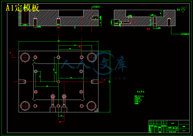
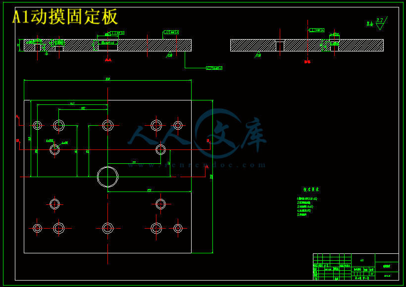
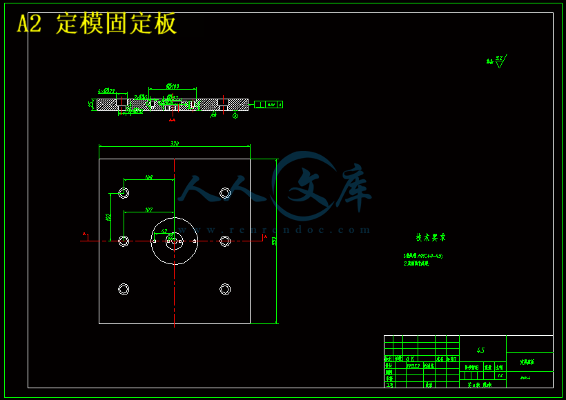
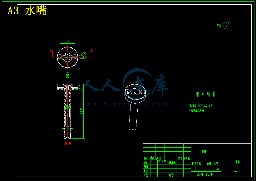
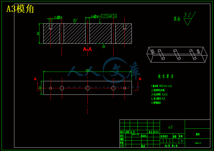
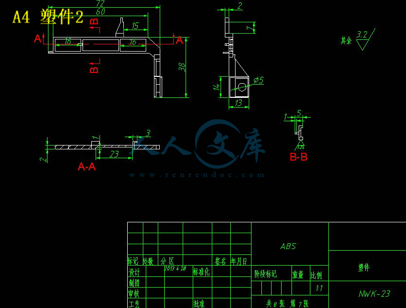
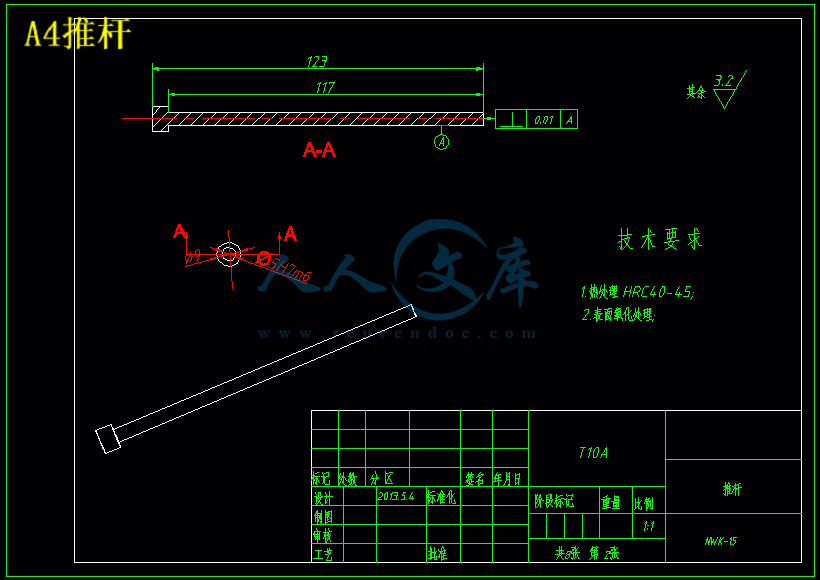
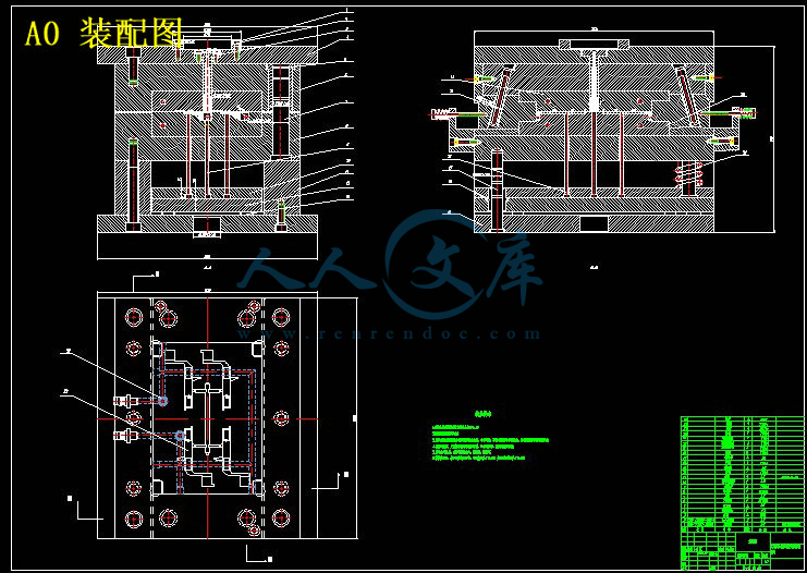
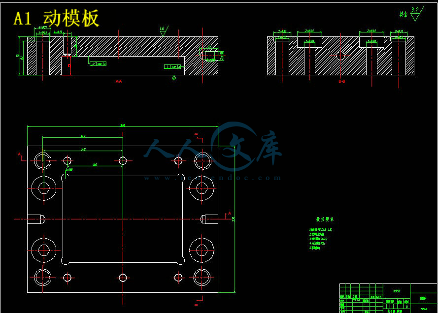
玩具照相机某零件支架注塑模具设计【10张CAD图纸和说明书】

收藏

压缩包内文档预览:
预览图 预览图 预览图 预览图 预览图 预览图
编号:10115677    类型:共享资源    大小:1.52MB    格式:RAR    上传时间:2018-05-22 上传人:俊****计 IP属地:江苏
40
积分
关 键 词:
玩具 照相机 零件 支架 注塑 模具设计 10 cad 图纸 以及 说明书 仿单
资源描述:

摘要

模具是工业生产的基础工艺装备,也是发展和实现少无切削技术不可缺少的工具。它在工业生产中使用极为广泛,是当代工业生产的重要手段和工艺发展方向,许多现代工业的发展和技术水平的提高,在很大程度上取决于模具工业的发展水平。因此,模具技术发展状况及水平的高低,直接影响到工业产品的发展。也是衡量一个国家工艺水平的重要标志之一。本次毕业设计的题目是照相机某零件支架注塑模具设计。本文主要论述了塑料注射模的基本原理和设计过程,并着重讲述了充电器外壳注射模的设计过程。首先,讲述了模具的作用和国内外的发展状况及其发展方向。然后论述了方案的选择和确定。再次对于所确定的方案给出了详细的设计过程和计算过程,最后还对所设计的模具进行了经济性可行性分析。

总的来说,所设计的这套模具经济合理,可行性强,生产方便,是一套实用性较强的模具。


关键词:注射模;定模;动模;抽芯;斜导柱

Abstract

      The molding tool is a foundation craft that industry produce to equip, it also a development with realizes the little having no slice the indispensable tool in the technique of cutting  .It is in industry produce the usage is extremely extensive, it an important means that contemporary industry produce to develop the direction with the craft, many modern industrial developments with horizontal exaltation in technique, be decided by the industrial development in molding tool level to a large extent. Therefore, moldings tool technique development condition and horizontal and high and low, affect the development of the industry product directly. Too is to measure the one of the horizontal and important markings in a national craft.

     The graduation project title is the camera bracket a parts injection mold design., this text discussed primarily the plastics injects the basic principle of the mold with design the process, combining to emphasize to relate the Chargers shell inject the design process of the mold. First, related the function of the molding tool with domestic and international development condition and its development directions. Then discussed the choice of the project with certain. Returns a project for making sure give a detailed design process with compute process; very much again the molding tool to design to preceded the economic viability assessment.

Total to say, a this set of molding tools for designing economy reasonable, the possibility is strong, producing the convenience, it a stronger molding tool in a set of function.


Keyword: Inject the mold; Settle the mold; Move the mold; Take out core; Inclined slippery piece


目  录

1 绪论 1

 1.1题目背景意义 1

   1.2塑料工业简介 1

   1.3我国塑料模具现状 2

   1.4塑料模具具发展趋 3

   1.5本文主要研究内容 3

2 制品的分析 4

   2.1制品的简介 4

      2.1.1对制品的分析主要包括以下几点 4

      2.1.2本设计中塑件各项要求 4

   2.2制品的工艺性及结构分析 4

      2.2.1结构分析 5

      2.2.3材料的性能分析 5

   2.3注射成形过程 7

      2.3.1 ABS的注射工艺参数 7

      2.3.2 ABS的主要性能指标 7

3 模具制造 8

   3.1确定型腔数量及排列方式 8

   3.2模具结构形式的确定 8

3.2.1多型腔单分型面模具 8

3.2.2多型腔多分型面模具 8

3.3注塑机型号的确定 8

3.3.1注射机的选用原则 9

3.3.2有关制品的计算 9

3.3.3 注射机型号的确定 9

3.3.4注射机及各个参数的校核 10

3.4分型面位置确定 11

3.4.1分型面的选择原则 11

    3.5 浇注系统的设计                                              12

3.5.1浇注系统设计原则 12

3.5.2主流道的设计 12

3.5.3冷料穴的设计 14

3.5.4浇口的设计 15

3.5.5浇注系统凝料的脱出机构 16

3.6脱模推出机构的确定 16

3.6.1脱模推出机构的设计原则 16

3.6.2制品推出的基本方式 17

3.7抽芯机构的设计 17

3.7.1侧向抽芯机构 18

3.8合模导向机构的设计 18

3.8.1导向机构的分类 19

3.8.2本设计中导柱的设计 19

3.9排气系统的设计 19

3.9.1排溢设计 19

3.9.2引气设计 19

3.9.3排气系统 19

3.9.4该套模具的排气方式 19

3.10温度调节系统设计 19

3.10.1加热系统 20

3.10.2冷却系统 20

3.11模架的确定和标准件的选用 20

3.12成形零件的结构设计和计算 21

3.12.1定模(凹模)的设计 22

3.12.2型芯(凸模)的设计 22

4 塑料模具材料的选用及技术要求 24

   4.1塑料模具材料的性能要求 24

   4.2塑料模具零件选材原则 24

   4.3模具的精度要求 24

      4.3.1模具零件的公差与配合选择 24

5模具工作过程 25

  5.1成型前的准备 25

     5.1.1原料的检验和预处理 25

     5.1.2料筒的清洗 25

     5.1.3嵌件的预热 25

     5.1.4脱模剂的选用 25

5.2注射过程 25

5.3脱模过程 26

5.4制品的后处理 26

5.4.1退火处理 26

5.4.2调湿处理 26

总结 27

参考文献 28

致 谢 29

毕业设计(论文)知识产权声明 30

毕业设计(论文)独创性声明 31


1  绪 论

1.1题目背景意义

近几年,我国塑料模具工业有了很大发展,注塑模具制品的种类越来越多,在未来的模具市场中,塑料模具具发展速度将高于其它模具,在模具行业中的比例将逐步提高。在电子、汽车、家电、玩具等产品中,60%~100%的零部件,都要依靠模具成形。用模具生产制件所表现出来的高精度、高复杂程度、高一致性、高生产率和低消耗,是其他加工制造方法所不能比拟的。通过本课题的设计,应使我们在下述基本能力上得到培养和锻炼:1)塑料管件制品的设计及成型工艺的选择;2)一般塑料管件制品成型模具的设计能力;3)塑料制品的质量分析及工艺改进、塑料模具具结构改进设计的能力;4)了解模具设计的常用商业软件以及同实际设计的结合。使个人能力得到全面提高,以适应今后的工作。

内容简介:
Design optimization of an injection mold for minimizing temperature deviationAbstractThe quality of an injection molded part is largely affected by the mold cooling. Consequently, this makes it necessary to optimize the mold cooling circuit when designing the part but prior to designing the mold. Various approaches of optimizing the mold cooling circuit have been proposed previously. In this work, optimization of the mold cooling circuit was automated by a commercial process integration and design optimization tool called Process Integration, Automation andOptimization (PIAnO), which is often used for large automotive parts such as bumpers and instrument panels. The cooling channels and baffle tubes were located on the offset profile equidistant from the part surface. The locations of the cooling channels and the baffle tubes were automatically generated and input into the mold cooling computer-aided engineering program, Autodesk Moldflow Insight 2010. The objective function was the deviation of the mold surface temperature from a given design temperature. Design variables in the optimization were the depths, distances and diameters of the cooling channels and the baffle tubes. For a more practical analysis, the pressure drop and temperature drop were considered the limited values. Optimization was performed using the progressive quadratic response surface method. The optimization resulted in a more uniform temperature distribution when compared to the initial design, and utilizing the proposed optimization method, a satisfactory solution could be made at a lower cost.Key words : Injection molding, Cooling channel, Cooling analysis, PQRSM, Design optimization1. IntroductionThe cooling stage is the longest stage during the cycle time of the injection molding process. Therefore, the most effective method to reduce the cycle time is to reduce the cooling time. The cooling time is fundamentally determined by the part thickness and mold temperature, which creates a cooling time limitation. If the mold temperature and part thickness are uniform over a whole part, the cooling time is not a concern; however, non-uniform part thickness and mold temperature distribution lengthen the overall cooling time. A longer cooling time means poor temperature uniformity, which can cause the part to warp. This is especially true for large products, such as automotive bumpers and instrument panels. It is for these types of parts that temperature uniformity becomes the most important factor in mold design. We developed an automated optimization of the cooling circuit for an early part design in order to check the design validity. Usually the early part design is checked by the filing/packing and warpage analyses without a cooling analysis. This is because the assumption is that the mold temperature is uniform, which is not actually true.Providing a rapidly optimized cooling circuit for the designed part would help part designers correct their designThe optimization was designed to minimize the part temperature deviation using design variables such as the diameters and distances of the cooling channels and baffle tubes and the depths of the part from the mold surface of the cooling channels and baffle tubes. A commercial computeraided engineering (CAE) tool, Autodesk Moldflow Insight, was used for the cooling analysis. We successfully obtained an optimized cooling circuit in a time much shorter than can be achieved in a manual design. In order to develop the automated optimization of the cooling circuit for the practical mold design, practical design parameters such as the pressure drop limit and the coolant temperature rise were considered in the optimization. The performance of the optimization technique can be affected by numerical noise in the responses. To find an optimum solution effectively when numerical noise exists, we performed an optimization by applying a regressionbased sequential approximate optimizer known as the Progressive Quadratic Response Surface Method (PQRSM)(Hong et al., 2000), which was part of a commercial process integration and design optimization (PIDO) tool known as the Process Integration, Automation andOptimization (PIAnO) (FRAMAX,2009). Figure 1. Finite element model of the product used for the optimization.2. MODEL AND CHANNEL CONFIGURATION2.1. Model ConfigurationThe model used for the optimization and CAE analysis was an automotive front bumper (FB). The size of the part was1,800600 mm, the element type was triangular and then umber of elements in the model was approximately26,000, with an average aspect ratio of 1.5. The model is shown in Figure 1.2.2. Cooling Channel ConfigurationThe cooling circuit for the automotive bumper mold is typically designed to have a horizontal plane of lin e cooling channels and to install baffle tubes from the line cooling channels. However, in this design, unnecessarily long baffle tubes attached at a line cooling channel may cause a high pressure drop in the cooling channel. The line cooling channels may not contribute to mold cooling due totheir large distance from the part surface. In order to improve the design, the line cooling channels were located along the offset profile of the part surface as shown in Figure 2. The end points of the baffle tubes were also located on the offset profile along a line cooling channel.Either the line cooling channels or baffle tubes were located on the offset profiles with equal arc distancesbetween them.3.FORMULATION3.1. Design ConstraintsThe limitation of the pressure drop and the temperature rise between the inlet and outlet of cooling channel should also be considered in the design of the mold cooling circuit. A high pressure drop usually occurs in a needlessly long cooling circuit. In a long cooling circuit, the flow rate of coolant is low, which results in a high mold temperature and a high temperature rise at the outlet. The design defect could eventually be found in the cooling analysis; however, the optimization is already time consuming, so it is better to instead apply the limits as constraints in the optimization.In this work we assumed that 4 line cooling channels were connected in series as a cluster, as shown in Figure 3. Clusters are connected in parallel by a manifold. Usually, the maximum pressure drop in a cluster is limited to 200kPa, and the maximum temperature rise at the outlet is 5oC(Menges et al., 2001). In the cooling analysis, each line cooling channel is regarded as a separate independent circuit for convenience. Because there were 4 line cooling channels in a circuit, the limits on the pressure drop and the temperature rise in each line cooling channel were 50kPa and 1.25oC, respectively. We also have an additional constraint due to the fact that the diameter of the baffle tube must be greater than or equal to the diameter of the coolingchannel because the baffle tube has lower heat removal efficiency than the cooling channel. where G1 is the constraint on pressure drop, G2 is the constraint on temperature rise, and G3 represents the subtraction of the diameter of the baffle tube from the diameter of the cooling channel.Figure 2. Configuration of cooling channels located along the offset profiles.3.2. Design VariablesIn this work, the diameters, distances and depths of the line cooling channels and baffle tubes were chosen as design variables for optimization. The total number of design variables was 6 as shown in Table 1. Typically, the diameters of the cooling channels and baffle tubes are determined by the mold designer according to their rule of thumb (Rhee et al., 2010). However, it has been examined in great detail among the mold designers. Table 1 shows the design variables with their ranges and initial values.The minimum values for the cooling channel distance,baffle distance and baffle depth were determined by the constraints of the machining requirement. The maximum values of cooling channel distance and baffle distance were determined by the empirical maximum obtained from the mold designers. The baffle distance was a discrete variable due to a restriction in the automated use of the CAE software. In this work, the baffle distances for optimization were 60, 90 and 120 mm.Figure 3. Clusters consisting of 4 cooling channels with baffle tubes.Figure 4. Scheme of the temperature field by the cooling channels.3.3. Objective FunctionA principal purpose of the mold cooling circuit optimization is to achieve uniform temperature distribution over the part. The uniform temperature distribution means that the temperature deviation caused by the cooling channels is minimized, as shown in Figure 4. The objective function in the optimization was the standard deviation of part temperature as shown in Equation (4). The part temperature was an arithmetic average of the upper and the lower surfaces of the mold halves. The mold surface temperature was calculated from the finite element of the part. where is the standard deviation of the part temperature, E i is the temperature of i-th element, Ew is the average temperature of the entire triangular elements, and N is the number of elements.4. OPTIMIZATION4.1. Parametric StudyIn order to examine the effects of the design variables on the objective function,pressure drop and temperature rise, parametric studies were carried out. A parametric study was performed by changing a variable in a certain range while keeping all other variables fixed. Figures 5-7 show the results of parametric studies for the objective function,pressure drop temperature rise, respectively. In each figure,the x-axis indicates the levels of design variables. Every design variable was divided into 11 levels from its lower bound to its upper bound. -5 and 5 mean the lower and upper bounds, respectively.When examining the temperature deviation, the diameter of the cooling channels shows little influence to the objective function (see Figure 5.). This result was predictable because the cooling channel affects the part temperature to a lesser degree than the baffle tubes in the automotive bumper mold. The automotive bumper moldhas a deep core so that the mold cooling depends upon the baffle tubes rather than the cooling channels. Another reason of the lack of influence can be that the flow state inthe cooling channel remains turbulent in the range of the parametric study. The cooling channel usually has a smaller diameter than the baffle tube. When the flow in the baffle tube is kept in the turbulent state, the flow in the cooling channel will be in the turbulent state. The diameters of the baffle tubes show a tangible influence when it increases above a certain value. Increasing of the diameter changes the flow in the tube to a laminar flow state. This is the cause for the lower heat transfer coefficient when compared to the turbulent flow state. This is why the temperature deviation becomes larger when the baffle tube diameter increases. Among all parameters, the baffle depth shows the largest influence on the objective function, as shown in Figure 5.As the baffle depth increases, the objective function increases. This means that the deeper location of the baffle tubes causes the temperature deviation to increase. Also, it confirms that the cooling of the automotive bumper mold depends upon the baffle tubes.The diameters of the cooling channels and the baffle tubes have the highest influence on the pressure drop in the cooling circuit, while the other variables show little influence (see Figure 6.). As the diameters increase, the pressure drop decreases after a certain value. This is also a predictable result as a larger diameter decreases the pressure drop.The influences of the temperature rise at the outlet are shown in Figure 7. The most influential parameters are the baffle diameter and the channel distance. The influence of the baffle diameter shows the highest values in the range from -1 to 3. In the case of the smaller baffle diameter, the reduced surface area for the heat transfer may cause a smaller temperature rise, while the larger baffle diameter may cause the lower heat transfer coefficient due to the lower flow rate.The increased channel distance means that each cooling channel takes up a larger area of the part surface with a larger amount of heat removal. This may give a physical explanation to why the increase of the temperature rise increases with channel distance. The fluctuations shown in Figure 7 are supposed to be numerical noise.Figure 5. Parametric study result of temperature deviation(objective function).5. CONCLUSIONIn this study, we carried out the optimization of the cooling circuit for an automotive front bumper. The design objective was to minimize the temperature deviation while satisfying all constraints. There were three design constraints that included the pressure drop, temperature rise and aspect ratio, in addition to side constraints on six design variables.Among the six des
温馨提示:
1: 本站所有资源如无特殊说明,都需要本地电脑安装OFFICE2007和PDF阅读器。图纸软件为CAD,CAXA,PROE,UG,SolidWorks等.压缩文件请下载最新的WinRAR软件解压。
2: 本站的文档不包含任何第三方提供的附件图纸等,如果需要附件,请联系上传者。文件的所有权益归上传用户所有。
3.本站RAR压缩包中若带图纸,网页内容里面会有图纸预览,若没有图纸预览就没有图纸。
4. 未经权益所有人同意不得将文件中的内容挪作商业或盈利用途。
5. 人人文库网仅提供信息存储空间,仅对用户上传内容的表现方式做保护处理,对用户上传分享的文档内容本身不做任何修改或编辑,并不能对任何下载内容负责。
6. 下载文件中如有侵权或不适当内容,请与我们联系,我们立即纠正。
7. 本站不保证下载资源的准确性、安全性和完整性, 同时也不承担用户因使用这些下载资源对自己和他人造成任何形式的伤害或损失。
提示  人人文库网所有资源均是用户自行上传分享,仅供网友学习交流,未经上传用户书面授权,请勿作他用。
关于本文
本文标题:玩具照相机某零件支架注塑模具设计【10张CAD图纸和说明书】
链接地址:https://www.renrendoc.com/p-10115677.html

官方联系方式

2:不支持迅雷下载,请使用浏览器下载   
3:不支持QQ浏览器下载,请用其他浏览器   
4:下载后的文档和图纸-无水印   
5:文档经过压缩,下载后原文更清晰   
关于我们 - 网站声明 - 网站地图 - 资源地图 - 友情链接 - 网站客服 - 联系我们

网站客服QQ:2881952447     

copyright@ 2020-2024  renrendoc.com 人人文库版权所有   联系电话:400-852-1180

备案号:蜀ICP备2022000484号-2       经营许可证: 川B2-20220663       公网安备川公网安备: 51019002004831号

本站为文档C2C交易模式,即用户上传的文档直接被用户下载,本站只是中间服务平台,本站所有文档下载所得的收益归上传人(含作者)所有。人人文库网仅提供信息存储空间,仅对用户上传内容的表现方式做保护处理,对上载内容本身不做任何修改或编辑。若文档所含内容侵犯了您的版权或隐私,请立即通知人人文库网,我们立即给予删除!