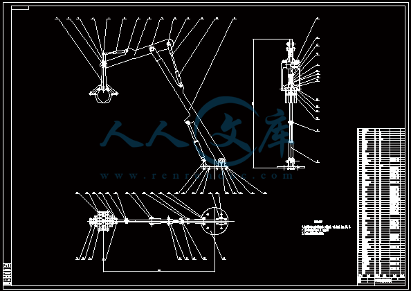
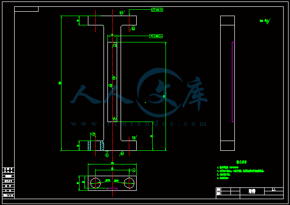
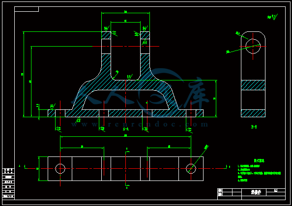
资源目录

压缩包内文档预览:
编号:10182893
类型:共享资源
大小:4.81MB
格式:ZIP
上传时间:2018-06-11
上传人:机****料
认证信息
个人认证
高**(实名认证)
河南
IP属地:河南
50
积分
- 关 键 词:
-
小型
吊装
设计
cad
图纸
- 资源描述:
-


- 内容简介:
-
下载后文件包含有 CAD 图纸和说明书,咨询 Q 197216396 或 11970985摘 要本设计是受日常生活启发而设计,在日常生活中,砍伐的树木在装车时几乎全是靠人力将树木一根一根的抬上车去。费时又费力,而且效率非常低。因此,想设计一种简单的吊装机执行机构来实现这一过程,以机械力替代人力,从而减小人的劳动强度,同时也可以节约更多的成本。该小型吊装机同时可运用在其抱合,起重范围之内的整体物件的起吊安装。设计该小型吊装机综合运用了机械原理,机械设计,理论力学,材料力学等学科知识。其执行起吊机构是这次设计的主题,总体要求执行机构有足够的刚度和强度,实用范围尽量广。 【关键词】执行机构、设计、刚度、强度下载后文件包含有 CAD 图纸和说明书,咨询 Q 197216396 或 119709851AbstractThis design is designed by the daily life inspired。In daily life,the trees which be hewed in loading is almost entirely by men carried them onto the truck, Slow and arduous, and efficiency is very low Accordingly, want to design a simple hoisting machine actuators to achieve this process,To replace mechanical force of human, thus reduce labor intensity,Also can save more cost。This small hoisting machine also can be used in its embrace range,Lifting the whole thing within the hookon installation。Design the small hoisting machine comprehensive use of the mechanical theory,Mechanical design,Theoretical mechanics,The mechanics of materials, and other disciplines knowledge。The theme execution of this design agency is crane-vehicle,General requirements actuators have enough stiffness and strength, practical scope。【Key words】Actuators; Design;Stiffness;Strength下载后文件包含有 CAD 图纸和说明书,咨询 Q 197216396 或 119709852目 录摘要 11 前言 22 小型吊装机执行机构设计 22.1 设计参数22.2 设计原理22.3 功能分析32.4 零件设计32.4.1 设计分析32.4.2 抱紧机构零件建模32.4.3 抱紧机构上液压缸设计计算102.4.4 起重机构建模12(一)零件建模12(二)起重机构分析17(三)起重机构上液压缸行程及压力计算192.5 零件校核223 液压缸设计和计算303.1 液压缸整体设计303.2 强度校核 31总结与体会33致谢词34参考文献35下载后文件包含有 CAD 图纸和说明书,咨询 Q 197216396 或 1197098531 前言随着经济的发展,科技的进步,传统的人力劳动正渐渐的被机械劳动替代。但在远离城市的乡村,基本都是人力劳动为主,最实在的例子就是在将砍伐的树木装车车时几乎全是靠人力抬。实在没人力劳动时所用的吊机也是以绳子为主,但是绳子需要人为装卸,效率比较低。因此想设计一种吊机的执行机构,这种吊机只需要一个操作人员操作,简单方便,能大大的提高工作效率。2 小型吊装机执行机构设计2.1 设计参数本设计根据实际需要,初步预设计起吊物件最大质量 M=500Kg,最大起吊高度 H=3m,起吊物件最大直径 D=500mm,起吊物件最长 L=4m2.2 设计原理该设计原理主要是运用机械原理知识,其机构设计原理图如图 1图 1 执行机构原理图如图所示:由液压缸 1 带动连杆 3 上下做直线运动,连杆 1、2 和连杆 3 由转动副连接,连杆 1、2 和连杆 4 也是由转动副连接。因此当连杆 3 上下运动时。便能带动连杆 4 张合运动,其中,当连杆 3 向上运动时,连杆 4 张开运动,反之,当连杆 3 向下运动时,连杆 4 合拢运动,因此可以抱紧所要提升的物件。连杆 5左端与液压缸 1 固定件用转动副连接,连杆 5 右端与液压缸 3 连接。连杆 5 同时又与连杆 6 通过转动副连接。因此,当液压缸 3 伸缩时候便可带动连杆 3 转动,左端固定件则可以上下移动。液压缸 2 也通过转动副连接,主要作用是保持左端固定件保持垂直。连杆右端与固定架通过转动副连接,液压缸 4 与连杆 6 及固定架通过转动副连接,因此在液压缸 4 在伸缩运动时便可带动连杆 6 旋转,最终达到左端固定件升的更高的要求。下载后文件包含有 CAD 图纸和说明书,咨询 Q 197216396 或 1197098542.3 功能分析该起吊机构在起吊一些类似树木,钢材的圆形物件时,相比较传统的绳索起吊机构有较大优势。首先,在传统的绳索起吊机构中,需要人为的将物件装上起吊机构,在放下物件时候也需要人为的去卸载,而且传统的绳索起吊机构在起吊物件时候不能限制物件转动,左右移动,同时在卸下物件时候也需要人为参与,容易导致安全事故的发生。其次,传统的以绳索起吊机构多以电机实现对物件的起吊运动,如果遇到超载现象容易导致电机烧坏。而该执行机构相比传统的绳索吊装机构有明显的优势。首先,在人力上只需要一个人便能完成,而且安全系数更高。其次,该机构采用液压系统做起吊的输出力,这样可以使整个机构在起吊运动过程中更加平稳。其次,该机构限制物件在起吊时的转动和左右移动的自由度,从而可以保证机构运动时更加平稳。再次,采用液压系统来驱动机构运动可以有效的保证电机等元件的安全,在超载的情况下可以在液压系统中通过安全阀来控制。2.4 零件设计2.4.1 设计分析设计参数中要求起吊物件最大质量 M=500Kg,最大起吊高度 H=3m,起吊物件直径 D=500mm,最长 L=4m根据设计原理图,机构所用材料除液压缸部分外全部采用 20 钢。20 钢性能如下: 牌 号 : 20 钢标 准 : GB/T699-1988力 学 性 能 :抗 拉 强 度 )42(0)(MPab屈 服 强 度 5s伸 长 率 %5)(断 面 收 缩 率 )(硬 度 : 未 热 处 理 , HB156密 度 : 7.85 3/kg0m2.4.2 抱 紧 机 构 零 件 建 模 根据设计原理图,采用三维软件 UG 建立抱紧机构的模型(1) 建立模型 1 如图 3下载后文件包含有 CAD 图纸和说明书,咨询 Q 197216396 或 119709855图 3 模型 1(2) 建立模型 2 如图 4图 4 模型 2(3) 建立模型如图 5下载后文件包含有 CAD 图纸和说明书,咨询 Q 197216396 或 119709856图 5 模型 3(4) 建立模型 4 如图 6图 6 模型 4(5) 建立模型 5 如图 7下载后文件包含有 CAD 图纸和说明书,咨询 Q 197216396 或 119709857图 7 模型 5(6) 建立模型 6 如图 8图 8 模型 6(7) 建立模型 7 如图 9下载后文件包含有 CAD 图纸和说明书,咨询 Q 197216396 或 119709858图 9 模型 7(8) 建立模型 8 如图 10图 10 模型 8(9) 建立模型 9 如图 11下载后文件包含有 CAD 图纸和说明书,咨询 Q 197216396 或 119709859图 11 模型 9(10)建立模型 10 如图 12图 12 模型 10抱紧机构各个零件建模完成后,将各个零件进行装配,其装配模型如图 13 毕业设计(论文)英文翻译年级、 专业: 2007 级机械设计制造及其自动化 姓 名:学 号:指 导 教 师:Journal of TerramechanicsVolume 48, Issue 2, April 2011, Pages 157-168 The design process of a self-propelled floor craneDaryoush Safarzadeh, Shamsuddin Sulaiman,Faieza Abdul Aziz, Desa Bin Ahmad,and Gholam Hossein MajzoobiAbstractIn order to prevent the hazards associated with the crane application in workshops and factories, a self-propelled hydraulic floor crane with wire remote control was designed. The main focus was directed on remote control of the craneoperations such as rotation of booms, rear and forward movements, changing travel speed, steering, braking and hook rotation. This configuration prevents the hazards and damages which may be created due to the proximity of operator to crane and provides the feasibility of utilizing the crane in crowded manufacturing areas, fields and hazardous environments. Research into the stability of crane on a slope route was also performed to obtain the equations of stability in static and dynamic conditions and recognition of the ways to enhance the stability. To validate the research work, a scale-model prototype was built to test the manner of controlling the crane operations from afar.Research highlights We design a crane with wire remote control to decrease hazards and to improve performance. It can be used in hazardous environments and fields. Remote loading and unloading of payload are feasible by use of an articulated hook. We suggest appropriate approaches to convey huge loads and to suppress payload sway.Keywords: Crane Hazards; Hydraulic; Remote control; Self-propelled1. IntroductionCranes are devices utilized for loading, unloading and transmitting the loads. They are profitable devices but hazardous in nature. We knew the crane activities responsible for 4% of the reported accidents and according to OSHA regulations, about 15.2% of crane events are occurred in manufacturingenvironments. Many researches have been performed regarding the causes of injuries and death from cranes 。Crane accidents have been grouped in the following categories according to NIOSH (National Institute of Occupational Safety and Health) report, including: swinging loads, overturning of cranes, falling loads, crushing between moving parts of cranes, falls of people from cranes, power line contact, overloading, contact the hook assembly with boom tip, obstruction of vision, assembly and disassembly of boom. Crane hazards are normally related to design and crane use. From a safety point of view, one of the most important issues in design of a crane is determination of stability. Stability of ranes has been studied by some researchers。 Weak segments, stress, strain, displacement, critical points and strength of parts under definite loads are determined by computer aided finite element analyses. Strength of the components versus the applied loads is determined based on FOS (factor of safety). For a safe performance, FOS is typically considered more than 1. Hydraulic floor crane is a kind of crane which has been used in workshops and factories from olden times. Basically, it is composed of a base, a column, a boom and a hydraulic cylinder for hoisting the boom. Nowadays, its application has been limited because of innumerable defects. The major research contribution of this paper is the use of CAD to design and develop a wire remote control hydraulic floor crane for the aims of decreasing the hazards, improving the performance and efficiency compared to the existing types and application in various locations such as hazardous environments and fields. Hence the main focus was directed on hazards reduction. Furthermore, the design has been also accomplished based on the required functions to perform the corresponding operations and employing peculiarities of the existing types considering their defects including hand-operated actuation, lacking of motor supplies, low safety, slow response and low speed。2. Design processThe proposed solution to control the sway is to install a platform for placing the payload during displacement 。Another benefit of this measure is to reduce overturning of the crane due to the pendulum motion of payload during displacement. Overturning issue can also be controlled by increasing the stability of crane through the appropriate static and dynamic analyses and fortification of the components as well as the correct selection of the crane dimensions. The other approach to decrease the hazards is to control the crane performance from a distance by utilizing a wire remote control system. This system prevents the hazards which are created by the fall of payload and objects on the operator or the fall of operator off the crane. Increasing visibility is another approach to reduce hazards and to increase safety. According to OSHA regulations, safe use of a crane is compromised when the vision of an operator is blocked and employees cannot see what the others are doing. The crane size alone limits the operators range of vision and creates blind spots. The crane boom may obstruct the operators range of vision. Often a load is lifted several stories high and the crane operator must rely upon others to ensure safe movement of the load being handled. The accidents due to the visibility problems are also occurred by other transporting devices such as lift trucks. Collins et al. found that visibility problems account for more than 80% of forklift truck related accident such as striking pedestrians or other vehicles, falling-off a ramp or loading dock and turning over by hitting obstacles.The visibility can be increased in two ways: (a) Movement of the operator slightly far from the crane increases his visibility to control the crane operations from every side. That is a significant issue especially in busy locations or when the crane is carrying a huge load which limits the operator visibility. (b) Installing the wired or wireless camera in various spots of the crane helps the operator to control the entire crane operations in out of reach and hidden areas from afar (The entire crane systems are covered by a body to protect the moving parts and to prevent event to people. To enhance flexibility and maneuverability of the crane, a compacted size and a three-piece boom were proposed. A combination of an inverter and a DC electromotor with 4 kW power was utilized to control the rear and forward movement and changing speed of the crane from remote distance. However, in this system by varying the speed of rotation, torque will be maintained constant. Thus a mechanical system consists of several pulleys and belts were designed to reduce the initial speed and to raise the torque Therefore, changing speed by inverter will be accomplished in a limited range to give a travel speed between 0 and 2.88 km/h. The normal speed of travel is 2 km/h so that the operator can walk along with the crane The maximum speed is 2.88 km/h. For the speeds more than 2 km/h in traveling, the operator can sit on the body. The main part of the hydraulic system is directional control valve assembly consists of several four-way valves with three positions ,These valves are solenoid operated so that the port opening can be achieved by a current flow through the coils. A magnetic field provides electromotive force to move the especially shaped valve spool. This motion is opposed by a centering spring. The ports are represented by pump , the return tank, the actuator inlet chamber A and the actuator outlet chamber B ,Solenoid valves should be used in open-center system that in neutral, oil flows through the control valve and back to the reservoir.3. Field applicationDevelopment of the crane for application on fields and rough lands may satisfy some of the field requirements such as loading, unloading and displacement of the field implements and boxes of the crops and fertilizer. The conditions of the crane operation on fields differ from the smooth lands. These differences are related to the required power, traction force, wheel slip, rolling resistance, wind effect andstability of the crane which is exposed to the perpetual variations due to the irregularities of the ground and may eventually result in overturning of the crane. Hence, to adapt the crane for field application, some modifications in the wheel size and power would be required. For a driving wheel moving on the soil ,the soil reaction G is resolved into horizontal and vertical components. The horizontal component is assumed to act at a distance (r) below the wheel center and is divided into two forces, a gross traction force Ft and a rolling resistance force Rr.4. Manufacturing processTo ensure of the crane function, in addition to an initial scale-model, a small model of AC crane at a scale of 1:2.5 was also manufactured and the operations such as forward and rear movements, changing speed, rotation of booms, steering and hook rotation from remote distance were tested. Compared to the designed model, in this process some modifications were applied to drive system and location of solenoid valves due to the limitations at the provision of parts or lack of adequate space. The platform and body were not installed so that the internal sections of the crane to be in full view To control the hook operation, a wireless camera (model 803 color CMOS) with a receiver (A/V fine tuning type) was connected to the boom. The details were observed on a laptop. The entire crane operations could be controlled properly from remote distance via a control box which was located at the operators hands.5. Stability analysesThe most important process in design of a crane is stability considerations to satisfy the safety issues. This process includes the proper selection of dimensions, weight and shape in addition to analyze the status of the lateral and longitudinal stability of the crane. Stability analyses and determination of the rated capacity have been achieved in accordance with ISO 4305 standard 1991.6. ConclusionsThis paper presents different aspects to design of a crane with the aim to decrease the hazards associated with the crane application in manufacturing and crowded environments. The design process was essentially focused on remote control of the crane operations. This permits the operator to control the crane functions from a definite distance to prevent presumptive damages by reason of falling the payload, power line contact, falls of operator, overturning, crushing the parts and collision which may be created by swinging of payload during operation. Furthermore, other recommendations have been also presented to reduce the hazards during the crane performance. For instance, installation of a platform to place the payload during transmission to stop the sway, utilization of camera to avoid collision where the visibility is limited and augmentation of the stability through the selection of appropriate dimensions, materials, load distribution and factor of safety. Results of the stability analyses denote the possible ways to improve the stability condition of the crane. Other considerations were also achieved to improve the crane performance, including selection of a three-piece boom and a compacted size to enhance flexibility and maneuverability. Performance rapidity could be also raised through the use of two discrete electro motors for hydraulic and drive systems. The design is promising for the future development in crane industry and control systems for robotic applications.地面力学周刊48 期,第二版,2011 年 4 月出版,第 157-168 页自动地板起重机的设计过程Daryoush Safarzadeh, Shamsuddin Sulaiman,Faieza Abdul Aziz, Desa Bin Ahmad,and Gholam Hossein Majzoobi摘要为了防止吊车在车间和工厂的应用危险,一种自动远程控制液压地板起重机被设计而出。其主要焦点在远程控制起重机,像旋转吊杆,前进和后退运动。改变行走速度、转向、制动和吊钩的旋转。这种装置可以防止因起重机操作人员靠近起重机而带来的危险,同时提供了起重机在拥挤的危险环境制造领域的可行性。研究起重机在斜坡稳定性也能去获得从静态和动态稳定性的方程,并且可以识别加强其稳定性。为了验证此项研究内容,制造一个原型样机去测试从远程控制的起重机。研究思想我们设计了一个起重机用电线远程控制去减少危害和改善绩效。它可以用在危险的环境和领域里。远程加载和卸载通过使用一种挂钩来铰接是可行的。我们用适当的途径来传递巨大的高负载并且可以一直有效载荷的摇摆。关键词:起重机危害;液压;远程控制;自动推进1. 引言起重机式一种用来装卸并传递载荷的设备。他们是有用的设备但在本质上很危险。我们知道起重机事故在报告中约有 4%,并且根据职业安全与卫生条例,约有 15.2%的起重机事故发生在生产制造领域。很多研究表明起重机经常导致人的的受伤和死亡。起重机安全事故已经归组入美国国家职业安全与卫生院的类别,包括,摆动负载,起重机的颠覆,载荷下落,起重机活动件的破坏。人从起重机上坠落,电线接触,过载,挂杆顶部的挂钩连接,阻碍视线,起重机吊杆装配和拆卸,起重机的相关危害通常参照美国国家安全手册来设计起重机,其中最重要的一个问题是设计一个起重机的稳定性,起重机已经被一些学者所研究,弱区段、应力、应变、位移、临界点和在一定载荷强度下的零件负荷是由计算机辅助进行有限元分析。部件的强度是考虑安全因素的基础上由外载荷决定的。为了安全性能,安全因素通常应该超过 1。液压地板起重机是一种在以前已经应用于车间和工厂的起重机。基本上,它是由一个基座,一个圆柱,一个吊杆和一个液压缸起重吊杆。如今,因为它有很多缺陷已经很少应用,而此文的主要的研究贡献在于运用计算机辅助设计去设计发明一个远程控制的液压地板起重机目的是为了 减少危害,相比在典型的各样危险环境下提高性能和效率。因此主要焦点在危险的减少,此外,设计也已经完成在要求的功能去履行相应的操作基础之上采用独特的安装方式去解决包含起吊操作、电力不足、低安全性能、反应迟缓和低速度等缺陷。2.设计过程推荐的控制摇摆的解决方法是在移动时安装一个安放有效负载的平台。这个措施的另一个好处就是减少移动过程中起重机由于有效负载的摇摆运动而产生的翻转可能。翻转事件也可以通过增加起重机的稳定性来控制。这些可以通过合理的静态和动态分析,成分的加强以及正确的选择起重机的维度实现。另一个减少危险的方法是利用有线的远程控制系统远距离控制起重机。这个系统可以防止由有线负载和操作员身上物体的掉落或者操作员掉下起重机产生的危险。增加能见度是另一个减少危险增加安全的方法。根据 OSHA 规则,起重机的安全使用会在操作员的视线被阻挡和被雇佣人不能看见其他人在做什么的时候得不到保障。只是起重机的大小就能限制操作
- 温馨提示:
1: 本站所有资源如无特殊说明,都需要本地电脑安装OFFICE2007和PDF阅读器。图纸软件为CAD,CAXA,PROE,UG,SolidWorks等.压缩文件请下载最新的WinRAR软件解压。
2: 本站的文档不包含任何第三方提供的附件图纸等,如果需要附件,请联系上传者。文件的所有权益归上传用户所有。
3.本站RAR压缩包中若带图纸,网页内容里面会有图纸预览,若没有图纸预览就没有图纸。
4. 未经权益所有人同意不得将文件中的内容挪作商业或盈利用途。
5. 人人文库网仅提供信息存储空间,仅对用户上传内容的表现方式做保护处理,对用户上传分享的文档内容本身不做任何修改或编辑,并不能对任何下载内容负责。
6. 下载文件中如有侵权或不适当内容,请与我们联系,我们立即纠正。
7. 本站不保证下载资源的准确性、安全性和完整性, 同时也不承担用户因使用这些下载资源对自己和他人造成任何形式的伤害或损失。

人人文库网所有资源均是用户自行上传分享,仅供网友学习交流,未经上传用户书面授权,请勿作他用。
 川公网安备: 51019002004831号