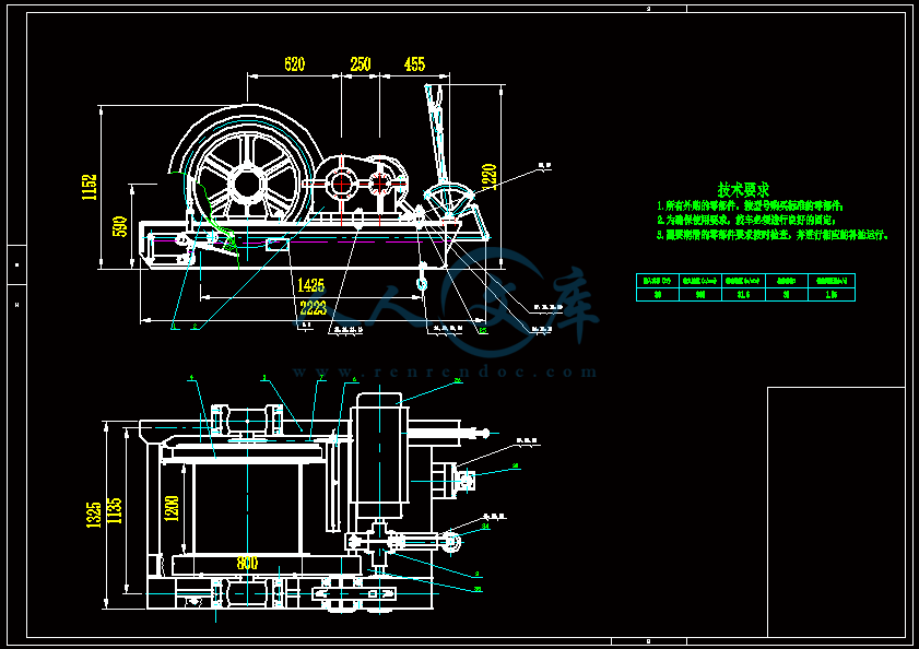
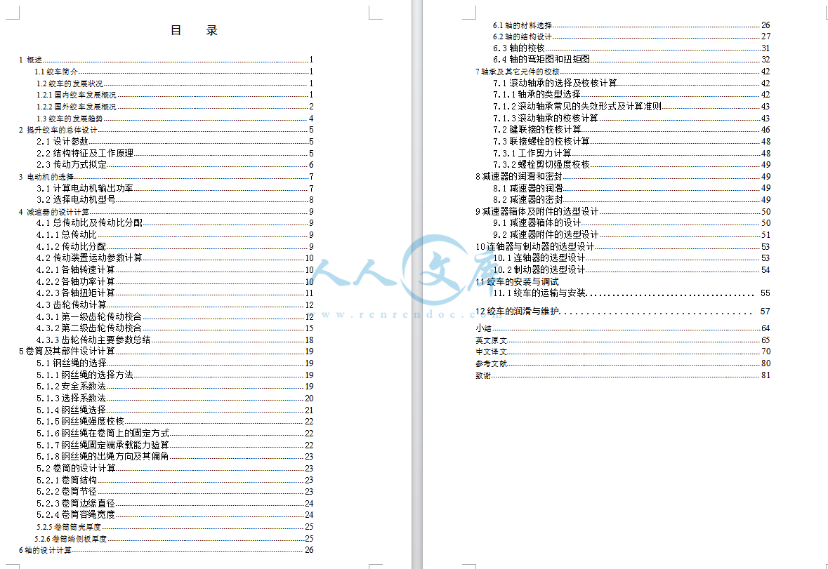
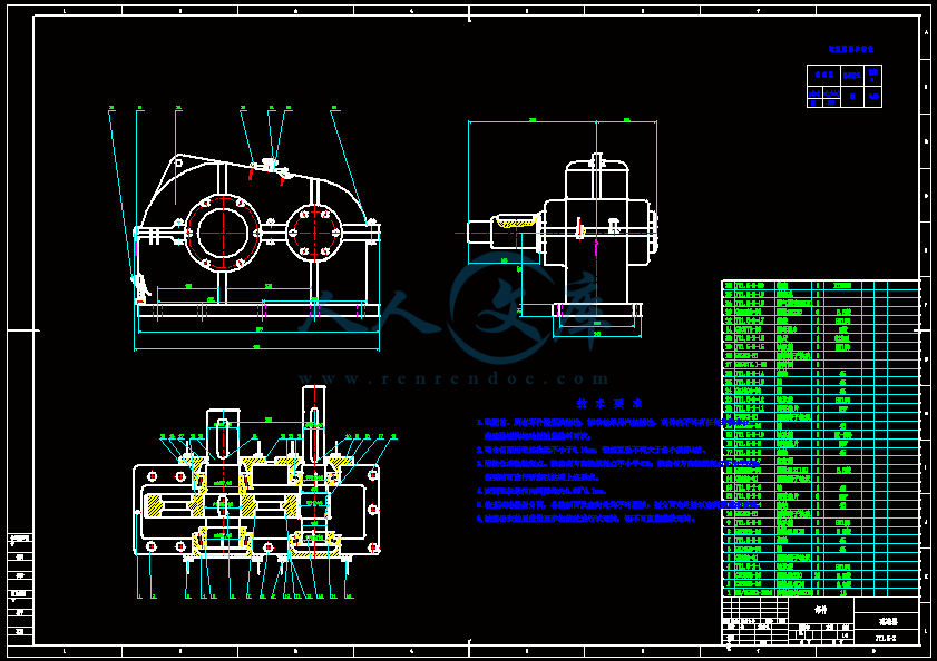
JT提升绞车设计【含10张AD图纸、说明书】
收藏
资源目录

压缩包内文档预览:
编号:15969991
类型:共享资源
大小:6.73MB
格式:ZIP
上传时间:2019-03-10
上传人:机****料
认证信息
个人认证
高**(实名认证)
河南
IP属地:河南
50
积分
- 关 键 词:
-
含10张AD图纸、说明书
提升绞车设计
JT提升绞车
jt提升绞车】jt提升绞车
- 资源描述:
-


- 内容简介:
-
2009IEEE 的学报关于机械工程和自动化的国际会议8月9-12日 长春 中国研究关于数控内齿轮基准轮磨技术任小忠,苏建新和邓小忠 任小忠机械工程专业 河南重点实验室河南科技大学 现代机械设计和翻译系洛阳 河南省 中国 洛阳 河南省 中国ren_xiaozhongI26.com ren_xiaozhongI26.com摘要齿轮研磨广泛地应用于有着坚硬面的最后的传动机构。内齿轮传动机构基准轮磨比传统传动机构轮磨占优势。基准轮磨精确度取决于基准轮上的涂料技术达到一个好的范围。为了要确定齿形精确度,一种基准轮上涂料装置藉由使用金钢石旋转来上涂料的工具得到开发。基于改动原则,为模齿上涂料准备数控程序表的渐开线,而且上涂料动作被数控控制器控制。为了要减少涂料误差,让传动机构齿平均地分配在一个圆也非常重要。为了要提高齿分割精确度,一个名为跳跃分割的齿轮研磨方法的类型被计划,数控机床齿轮研磨程序表也被开发。在自主开发数控机床上进行磨轮修整实验和齿轮研磨测试内齿轮磨。在这一个物品中进行的内齿轮磨实验技术有效。索引-内齿轮基准磨轮跳跃分割修整传动机构基准磨床I. 介绍由太阳轮组成的行星的变速箱装置,行星传动机构和内齿轮有一系列出自立着的利益1,而且广泛地被用于各种不同的变速组件,像是变速器、渐缩管和差速器装置。传动机构用硬面广泛地越来越被用于用高速、高度精密度,耐用、高度效率2 适应变速箱的行星的变速箱装置。在现在,磨已经在中国被太阳轮和行星传动机构有效率地应用。键将解决该如何用硬面解决内齿轮的高有效率轮磨,以便整个行星轮的制造业的精确度和装载能量能被提高。美国标准磨的传统的发生根据许多状态作比较,用传统方法很难了解内部齿轮.与高有效率轮磨相比较,磨的基准有许多利益,举例来说,对设计的机器,它的机制效率是 5-7,甚至是传统磨的10倍3.虽然数控机床内齿轮基准磨床已经在一些发达国家中被制作,但是,机器很昂贵,因而许多客户不能负担它而且必须找其他方法用硬面处理内齿轮。举例来说,在传动机构拉孔之后,内齿轮很容易被氮化。氮化之后没有任何较进一步的完工机制。明显地,它在没有磨下对传动机构的情况下在轮廓精确度和装载能量中符合需求是很困难的。对于这理由,一个数控机床内齿轮基准磨床的型被开发4,而且拥有中国5 的 P.R. 的自主知识产权.在传动机构基准轮磨中,无论是否齿能平均地在一个圆被分配或者不是最初的精确度分度,以及重要的标准测量传动机构能与变速箱一起取得资格与高的评价。当传动机构在高速运行时,而且在重载之下,它应该被要求增加齿腹硬突端而且减少齿误差6 。因此,一些主要技术以传动机构基准轮磨,像是齿分割精确度和磨轮修整技术,在这一个文章中被研究。2.齿轮研磨平面图的决心A.传动机构基准磨床的地面区划内齿轮基准磨床的所有安置在图 I中被显示. 被显示磨轮的旋转装置,一是最初的动作。Z 中的磨轮的运动桥线长且滑动 3 是桥方向的进刀机构。在 Y 桥线的垂直柱的运动是放射状的进刀机构。滑动 8 作为上涂料磨轮而且变更磨的位置。CNC 使旋转被重复, C 的台桥线被用来决定精密的齿分割。在滑动 8 上被展开的基准轮修整器 6 被用来在线上制作基准磨轮。B.齿轮研磨平面图的决心因为内齿轮用较大的直径,类似外齿轮基准磨的方法,也就是说,用基准磨轮,穿着齿槽孔7 的形, 是被提出的磨齿齿槽孔的中央位置。当磨轮上下地移动当做磨,使旋转台编入索引中一个齿。在这样 z 时代之后,一个传动机构的所有齿可能是连接的。因为内齿轮用较小的直径,因为磨的冒口是相对地大的,要在轮磨中把基准磨轮放入齿槽孔的中央位置是没有方法的。藉由分析内齿轮的相对位置造形磨轮,和考虑 CNC 机器可得的动作,一个磨的方法能被内齿轮在一个齿的两侧面可能藉由使用磨轮8 的一端分开地被磨方面所依据的较小的直径所应用.图1传动机构基准磨床的地面区划1,7- 原动机;2- 垂直的柱;3,8 CNC 的滑动;4- 磨轮架;5- CNC 旋转台;6 轮的修整器;9- 机械的滑动;10-手动的推进单位;2底3.分度精确度的控制旋转台的 CNC 被用于在上面提到的内齿轮基准磨床中被编入索引中。因此,积聚的误差主要取决于旋转台的分度精密度。因为使旋转台分解毕竟是不可能的,当小数数字场所在传动机构的连接齿之间在那里超越使旋转台的溶液运动,倒角误差会被生产。当编入索引的齿的数目相对很小时,误差不是非常清楚。但是当编入索引的齿的数目相当大时,比较大的积聚误差将会生产。较大的分度误差会引起被拒绝的传动机构。因此,应该采取措施减少或者除去它。一个新齿轮研磨方法叫 跳跃分割 在这一文章中被计划。因此叫做跳跃分割的方法磨一次在齿轮研磨中的每一个齿。理想的分度间隔,拨动最佳的齿跳过的数目,应该使倒角成为多数产生的误差中的最小,当小数部分拨动造形被一些齿超越使旋转台分解,如此有被减少到多数最小的积聚的误差。分度间隔不应该被齿数目 z 分开以避免在一些齿之中磨的重复。假如一个内齿轮是藉由内齿轮用 124颗齿磨基准用分度精确度 0.001 的装备使旋转台的 CNC 磨床旋转.如果跳跃分割没被用,当时相啮合的齿之間的倾斜角是2 =360/124 =2.903226在节点圆上齿形的一个齿槽孔的角的地方。能见到在轮磨 124颗齿中产生的倒角误差是0.000226x 124 =0.028=1.68假如分度间隔是 9,旋转台应该转 26.129032 仅此一次磨的。然后倒角误差是 0.000032.在这 124颗齿完全地被磨之后,全部的倒角误差是0.000032x 124 =0.004 =0.24 明显地,误差非常小。4.非标准轮廓轮的上涂料磨的传动机构基准比传统的传动机构轮磨占优势。齿形精确度主要地取决于要参考的基准轮的轮廓精确度。基于上涂料原则,有上涂料方法的两个类型:传统的和改革的。轮上涂料能藉由金钢石笔和金钢石轮来做。CNC 轮上涂料藉由发生方法需要高水准的 CNC 系统。而且与一个要以机器制造的传动机构的基圆直径的增大,轮修整器的尺寸和制造成本变得比较大。当上涂料根据金钢石笔旋转,笔点的高度和不平顺磨耗主要有在上涂料精确度方面的影响力。因此, CNC 轮上涂料装置用在改动原则上的金钢石桥距被开发。而且基准轮上涂料程序表也被准备。A、非标准的在改动中的轮上涂料原则藉由改动有着非标准的轮将根据在渐开线中找一系列轮廓节点到这基本的渐开线的叁数。直片段被用来连接两个大约相啮合的节点,结果适合渐开线,了解渐开线的改动。明确地,改动运动能藉由沿着两个直角的坐标被分开地移动两个 CNC 滑动,如 Fig.2 所示。因此,一个 2 D 的坐标系统藉由对渐开线的出发点的起源采取基圆中心建立像 Y 桥线一样,和中心的连接线,如 Fig.3 所示。假如渐开线在任何点 A 扩延的角是。藉由拿为初次的增量当做旋转的变数增加的。对应的坐标点能藉由依下列各项替换进入方程序被发现。点 A 的坐标是:= rbsin rbcos= rbcos + rbsin图2渐开线改动原则图3非标准改动的数学模型基圆的半径是:rbm z cosa 2点 A 的两极半径是:rA rb cosa A点 A 的扩延角是:tga Am位置传动机构的组件;z传动机构的齿数目;在节点圆中的传动机构的压力角;aA点 A 的压力角。B.上涂料误差的分析该如何选择的大小是改动程序的全部的关键。在大的之上会引起较大的改动误差,在小的之上会引起比较低的改动效率。如果依照机制精确度决定,当常态允许误差可能是改动精确度分度的想法。改动点的稠密度能藉由变更的价值,有改动的数量被改变磨利不只适宜的改动精密度但是增大改动效率。如图3显示,扩延的角在点 A 是,基圆中的对应的坐标点是A.点 A 的坐标能藉由替换进入方程序被发现。(1)当基圆准备磨 B,藉由把加入,渐开线中的对应的坐标点是点 B。点 B 的坐标能藉由替换被发现进入方程序之内的. (1)藉由为非标准的片段 AB 替换直线片段 AB ,最大误差在直线片段 AB 的中点牛顿中出现。藉由制造一个在一点相接 nm对基圆而且用渐开线把 MN 扩充到十字点 M,当时在基圆的 M 的扩延角是:M =arctg(xn/ Yn) + arccos(rb /ON) (5)那么MM = rb x M (6)ON = (7)Xn = (XA + xB) /2Yn = (YA + YB) /2 (8)MN的长度为MN = (9)检查是否能配合改动精密度。如果不能符合需求,为了要减少改动误差,当新节点应该再次减少所计算增量的一半。如果能符合需求,但是是在小的之上,当 2 为了要提高改动效率,用来计算新节点。C. 为上涂料较差的轮和模拟规画渐开线磨轮整形程序表藉由使用 VC 被准备当做开发中的工具。轮上涂料软件系统应该是四个组件:传动机构叁数输入和计算;改动误差计算和控制;渐开线上涂料定路线模拟;而且数控编码产量。 A 表示准备轮上涂料程序表的流程图。输入是传动机构叁数和非标准的改动精确度。产量是渐开线的改动点的价值。CNC 机制产生的密码经过了解自动的上涂料的 RS232 接口输入 CNC 组件。CNC 机制密码也能被用来模仿轮上涂料真正的上涂料前的作用。图5表示轮上涂料的模拟。它能被用来查证程序表的连续性和正确性。V. 轮廓非标准的轮上涂料装置图6 用金钢石轮举例说明一个磨轮修整。上涂料藉由金钢石轮的圆筒形的表面和表面之间的圆的隅角被做。从图中可以见到3 如果在金钢石轮的拱形中心的痕迹沿着磨轮分别地是有渐开曲线的,因上涂料而造形的磨轮轮廓的曲率半径不同于拱形中心的痕迹。基准磨轮的轮廓是内齿轮的一个凸面轮磨,它的轮廓半径少于拱形中心的痕迹。在作为外齿轮轮磨的基准磨轮的相反箱之上。在规画的数字控制部分的工具半径补整指导的使用能使被使用的轮廓与理论上的轮廓9 一致.图4轮上涂料程序表的流程图图5轮上涂料模拟图6轮上涂料的草图轮上涂料装置的 3D立体用金钢石轮抽制显示在 Fig.7。它有纺锭总成,驾驶总成,补给总成和底座等等整个的装置是装置在齿轮CNC 滑动的磨床,如 Fig.l 所示。金钢石轮的旋转装置被电力有关电动机驱使。补给运动沿着纺锭桥线被藉由齿轮磨床在CNC X 桥线滑动,和其他补给运动垂直被一个它本身的原动机驱使到纺锭桥线。非标准的改动藉由控制这两个补给运动而完成。图7磨轮修整装置6.轮上涂料及齿轮研磨实验A轮上涂料在基准齿轮磨床上安装轮上涂料装置。正确调整金钢石轮和要穿过的磨轮之间的相对的位置。CNC 系统和原动机开始。然后,随着程序表10 被准备好 ,金钢石轮在 X 桥线和 V 桥线中分别驱使两个滑动磨轮。图8表示轮上涂料装置在涂料状态上。图8上涂料状态中的轮的上涂料装置B.齿轮研磨要磨的传动机构是一个内齿轮 z80,m3, u 20和齿宽 b70 mm。第一,轮上涂料装置、工作件、使旋转台的中心和磨轮车架等应该设定成适当的位置,以便磨轮不干扰整个齿轮研磨程序的轮上涂料装置。第二,磨轮应该与齿轮研磨前和齿形相同的轮廓一起穿过。第三,藉由输入机制表运作仪表板,为了要确定磨的轨道是否正确,一定要做卸货试车。最后,能进行齿轮研磨。内齿轮磨的程序显示在 Fi.9。Fig.9.一个内齿轮被磨 基础传动机构用特殊传动机构检验单位用格兰申传动机构检验仪器检验。精密度用 6 级能确保是否在齿误差中,或齿对准误差而且确定误差。7.结论1)基于CNC 内齿轮基准磨床的开发,跳跃分割作为内齿轮轮磨。这一方法有利于确定齿分度精确度而且减少积聚的误差。2) 基于非标准的改动原则,建立非标准轮廓的数学模型。同样把可变的渐开线的扩延角和正常的公差当做一个强迫的状态,一个改动方法被制定。 3) 藉由分析上涂料动作,设计了基准轮上涂料装置,而且准备了轮上涂料程序表。4) 齿轮研磨和轮上涂料实验成功地进行。计划的内齿轮轮磨实验在这一个物品中的结果技术有效。齿轮研磨技术提供一个有效的提高方法来保证内齿轮的机制精确度。认证因中国的国立自然科学基础研究这一个主题, 受No.50575068支持,借着河南现代机械设计和变速箱系统的主要实验室No.KFJZ200706的基础。叁考 1 范四建、韩翠婵。”设计和制造非标准行星齿轮装置”,中国机械出版社,2000.2 尚向东、 金佳琪、付静顺。 传动机构机制精确度 ,中国机械出版社,2001。3周培 、 赵军 、 徐宝龙,等人”德国 CNC 传动机构磨床和齿轮研磨技术”,现代机械工程学、No9,pp.91-92,2002.9。4任晓忠 、 邓晓忠 、 苏建新 ,等人。”CNC计算机辅助传动机构磨床的基准设计”, 中国农业机械出版社, 39册, No 2,pp.144-146,2008.2。5 邓晓忠。 内齿轮基准磨床 ,国标ZL200520030867.8.2005.6 龚俊、刘永平 、赵雪 ,等人,”一项基于CNC 基准磨床工具来研究高标准锥形表面磨轮精密度分级的运算法则”,兰州大学出版社、 Vo1.38 、 No6, pp.54-57,2002.10。7 王平年 、 马宝丽,周培。对德国CNC 传动机构基准磨床调制解调器的介绍。Cfhi 技术、 No1,pp.31-33,2003.1。8 任晓忠 、 邓晓忠,苏建新。 多功能 CNC 传动机构基准磨床的设计 、制造技术加工工具、 No6,pp.71-73,2008.8。9 周玉山 、邵明,闵浩年。基准传动机构金属模的软件开发 、技术 (自然科学版)、 VoL33 、 No5,中南大学出版社,pp.23-25,2005.5。10 苏见信 、任晓忠,杜新生。 开发内齿轮和研究轮磨方法和数控机软件 、加工工具水力学、 Vo1.35 、 No10,pp.29-30,2007.10。Proceedingsofthe 2009 IEEE International Conference on Mechatronics and Automation August 9 - 12, Changchun, China Study on theCNC Internal Gear Form Grinding Technology Ren Xiaozhong, Su Jianxin and Deng Xiaozhong SchoolofMechatronics Engineering Henan UniversityofScience2-Vertical pillar;3,8-CNCslide; 4-Grindingwheel support;5-CNCrotating table;6-wheel dresser;9-Mechanical slide;I0- Manual driving unit; II - Bed III.CONTROL OF INDEXINGACC URACY A CNC rotating table is used in the internal gear form grinding machine mentioned above to index tooth. Therefore, the accumulative pitch error depends mainly on the indexing precision of rotating table. Because the resolutionofthe rotating table is limit after all, when the decimal digit placeof the included angle between adjacent teethofgear goes beyond the resolutionofthe rotating table, the rounding error would be produced. The error is not very clear when the numberof indexed teeth is relatively small. But when the numberof indexed teeth is quite large, the larger accumulative error would be produced. The larger indexing error would cause the ground gear rejected. Therefore, measures should be taken to reduce or eliminate it. A new gear grinding method called “jumping division“ is proposed in this article. So called jumping division means grinding once every several teeth in gear grinding. The ideal index interval, called optimal tooth numbers jumped over, should make the roundingerror minimum, which is produced when the decimal fraction part ofthe included angle formed by the several teeth goes beyond theresolutionoftherotatingtable,thushavingthe accumulative error decreased to minimum. The index interval should not be divided out by the tooth number z to avoid repeat grinding among the several teeth. 4524 Suppose an internal gear with 124 teeth is to be ground by meansofan internal gear form grinding machine, which is equipped with a CNC rotating table with indexing accuracy 0.001. Ifjumping division is not used, then the included angle between adjacent teeth is 2/3=360/124 =2.903226 where /3 is tooth profile angleofa tooth slot on pitch circle.Itcan be seen that the rounding error produced in grinding 124teeth is 0.000226xI24=0.028= 1.68“ Suppose the index interval is 9, the rotating table should tum 26.129032 for once grinding. Then the rounding error is 0.000032. After the 124 teeth are completely ground, the total rounding error is 0.000032xI24=0.004=0.24“ Clearly, the error is very small. IV.DRESSING OF INVOLUTEPROFILEWHEEL Gear form grinding has many advantages over gear generationgrinding. The tooth profile accuracy depends mainly on the profile accuracyofform wheel to be dressed. Based on the dressing principle, there are two kindsof dressing methods: generation and interpolation. The wheel dressing can be done by meansofdiamond pen and diamond wheel. CNC wheel dressing by meansofgenerating method needs high level CNC system. And with the increaseofbase circle diameterofa gear to be machined, the size and manufacture costofwheel dresser becomes larger. When dressing wheel by diamond pen, the height and uneven wear ofpen point have largely an influence on the dressing accuracy. Therefore, a CNC wheel dressing device with diamond wheel based on interpolation principle is developed. And form wheel dressing program is also prepared. A. Involute wheel dressing principle in interpolation To dress involute profile wheel by meansofinterpolation is to find a seriesofnode in the involute according to the basic parameters of involute. The straight segments connected by two adjacent node are used to fit the involute approximately, consequently,realizingtheinterpolationofinvolute. Specifically, interpolating movement can be done by moving two CNC slides along two orthogonal coordinates separately, as shown in Fig. 2. Therefore, a 2-D coordinates system is set up by taking base circle center as origin, and the connection lineofthe center to the starting pointofinvolute as Y axis, as shown in Fig.3. Suppose the spread angle at any point Aofinvolute is e. e as a variable increases in tum by takingDe as initial increment. The corresponding coordinates points can be found by substituting e into the equations as follows. The coordinatesofpoint A is: XA=rbsinerbecose YA=rbcose+ rbesine(1) Authorized licensed use limited to: CHINA UNIVERSITY OF MINING AND TECHNOLOGY. Downloaded on April 19,2010 at 03:05:34 UTC from IEEE Xplore. Restrictions apply. Fig. 2 Involute interpolating principle x x B. The coordinatesofpoint B can be found by substituting oe+eintoequation(1).Bysubstitutingstraightline segmentABfor involute segmentAB,the maximum error 8 appears in the midpoint Nofstraight line segmentAB.By making a tangent NM to base circle and extending MN to intersection point M with involute, then the spread angleofM in base circle is: eM=arctg(xn/Yn)+ arccosrr, / ON)(5) Then MM rb x eM (6) ON =“;xn2+ Yn2 (7) xll=(XA+xB)/2 YII=(YA+YB)/2 (8) The lengthofMN is MN=.JON2+rb2 (9) Then, the maximum error in the normal directionof involute is: o= MN= MM- MN To check whether 8 can meet the interpolation precision.If 8 can not meet the requirement, then the new node should be calculated again by decrease the increment byhalfin order to reduce interpolation error.If8 can meet the requirement, but 8 is over small, then 20 e is taken to calculate the new node so as to improve interpolating efficiency. B. Analysisofdressing error How to choose the magnitudeofDe is the key in whole interpolatingprocess.OverlargeDewouldcauselarger interpolation error, and over-small De would cause lower interpolating efficiency.IfDe is determined according to machining accuracy, then the normal allowable error can be thoughtofinterpolation accuracy index. The denseness degree ofinterpolation points can be changed by changing the value ofDe, having the numbersofinterpolation points not only meetinterpolationprecisionbutincreaseinterpolation efficiency. As shown in Fig.3, the spread angle at point A is e, the corresponding coordinates point in base circle is A. The coordinatesofpoint A can be found by substituting e into equation(1).When base circle turns to point B by adding De to e, the corresponding coordinates point in involute is point Fig. 3 Mathematical model of involute interpolation The radiusofbase circle is: rb=mzcosa/2 The polar radiusofpoint A is: rA = rb/cosaA The spread angleofpoint A is: e=tgaA where m-moduleofgear; z-toothnumberofgear; a-pressureangleofgear in pitch circle; aA-pressureangleofpoint A. (2) (3) (4) 4525 C.Programmingfordressing involute wheelandsimulation Involute grinding wheel dressing program is prepared by using VC+ as developing tool. The wheel dressing software system is supposed to be four modules: gear parameters input and calculation; interpolation error calculation and control; involute dressing route simulation; and NC code output. FigA shows the flow chart for preparing wheel dressing program. The input is the gear parameters and the involute interpolation accuracy. The output is the Cartisian valueofinterpolation pointofinvolute. The CNC machining code generated is input intotheCNCunitthroughRS232interfacetorealize automatic dressing. The CNC machining code can also be used to imitate the wheel dressing action before real dressing. Fig.5 shows the simulationofwheel dressing.Itcan be used to verify the continuity and correctnessofthe program. V.INVOLUTE PROFILEWHEELDRESSING DEVICE Fig.6 illustrates a grinding wheel dressing with diamond wheel. The dressing is done by meansofthe roundcomer between the cylindrical surface and faceofdiamond wheel.It can be seen from Fig. 3 thatifthe traceofarc center in diamond wheel is a partofinvolute curve along the grinding wheel, the curvature radiusofgrinding wheel profile formed by dressing is different from thatofthe traceofarc center. The profileofform grinding wheel is a convex for internal gear grinding, its profile radius is less than thatoftraceofarc center. The case is on the contrary for the form grinding wheel usedfor external gear grinding. Theuseoftool radius Authorized licensed use limited to: CHINA UNIVERSITY OF MINING AND TECHNOLOGY. Downloaded on April 19,2010 at 03:05:34 UTC from IEEE Xplore. Restrictions apply. Fig.4 Flow chartofwheel dressing program Base Slide Servo motor Drive assembly Spindle assembly 1“-Diamond wheel Fig. 6 Sketch mapofwheel dressing The 3D drawingofwheel dressing device with diamond wheel is shown in Fig.7.Itconsistsofspindle assembly, drive assembly, feed assembly and base etc. The whole device is installed on the CNC slide of gear grinding machine, as shown in Fig.l. The rotationofdiamond wheel is driven by electrical motor. The feed movement along the spindle axis is realized by means of the CNC slide in X axis of gear grinding machine, and the other feed movement perpendicular to the spindle axis is driven by a servo motorofitself. The involute interpolation is accomplished by controlling the two feed movements. Fig.? Grinding wheel dressing device VI.WHEELDRESSING AND G EARGRINDINGEXPERIMENTS A. Wheel dressing Install the wheel dressing device on the form gear grinding machine.Adjustcorrectlytherelativepositionbetween diamond wheel and grinding wheel to be dressed. Start CNC system and servo motors. Then, the diamond wheel is driven by two slides in X axis and V axis separately to dress grinding wheel following the prepared programIO. Fig.8 shows that the wheel dressing device was on dressing condition. N Output all coordinates and save program code Fig.5 Wheel dressing simulation :t#q).tIl) l!)MltI Q I)!litlAlUI IDIfl af- compensation instruction in NC part programming can make the dressed profile be consistent with the theoretical profile 9. 4526 Authorized licensed use limited to: CHINA UNIVERSITY OF MINING AND TECHNOLOGY. Downloaded on April 19,2010 at 03:05:34 UTC from IEEE Xplore. Restrictions apply. Fig.8 wheel dressing device on dressing condition B. Gear grinding The gear to be ground is an internal gear with z=80, m=3, u=20, and tooth width b=70mm. Firstly, the wheel dressing device, workpiece, centerofrotating table, and grinding wheel frame etc. should be set to proper position so that the grinding wheel would not interfere with wheel dressing device in whole gear grinding process. Secondly, the grinding wheel should be dressed with the same profile as the tooth form before gear grinding. Thirdly, by inputting machining program through the operation panel, the unloading trial run must be done in order to ensure the grindingtrack correct.Lastly, gear grinding can be carried out. The internal gear grinding process is shown in Fi .9. Fig.9.Aninternal gear being ground The ground gear is inspected by a special gear inspection unit with Gleason gear inspection instrument. The precision with grade 6 can be met whether in tooth error, or tooth alignment error and pitch error. VII.CONCLUSION I) Based on developed CNC internal gear form grinding machine, jumping division is used for internal gear grinding. This methodis beneficialto ensure the toothindexing accuracy and reduce the accumulative pitch error. 2) Based on theinvoluteinterpolationprinciple, the mathematical modelofinvolute profile is established. Taking the spread angleofinvolute as variable and the normal allowance as a constrained condition, a interpolation method is proposed. 4527 3) By analyzing the dressing motions, a form wheel dressing device is designed, and wheel dressing program is prepared. 4) Gear grinding and wheel dressing experiments are carried out successfully. The result of internal gear grinding experiment validates the grinding technology proposed in this article. The gear grinding technology provides an effective way to improve the machining accuracyofinternal gears. ACKNOWLEDGMENT This topic of research is supported by National Natural Science Fo
- 温馨提示:
1: 本站所有资源如无特殊说明,都需要本地电脑安装OFFICE2007和PDF阅读器。图纸软件为CAD,CAXA,PROE,UG,SolidWorks等.压缩文件请下载最新的WinRAR软件解压。
2: 本站的文档不包含任何第三方提供的附件图纸等,如果需要附件,请联系上传者。文件的所有权益归上传用户所有。
3.本站RAR压缩包中若带图纸,网页内容里面会有图纸预览,若没有图纸预览就没有图纸。
4. 未经权益所有人同意不得将文件中的内容挪作商业或盈利用途。
5. 人人文库网仅提供信息存储空间,仅对用户上传内容的表现方式做保护处理,对用户上传分享的文档内容本身不做任何修改或编辑,并不能对任何下载内容负责。
6. 下载文件中如有侵权或不适当内容,请与我们联系,我们立即纠正。
7. 本站不保证下载资源的准确性、安全性和完整性, 同时也不承担用户因使用这些下载资源对自己和他人造成任何形式的伤害或损失。

人人文库网所有资源均是用户自行上传分享,仅供网友学习交流,未经上传用户书面授权,请勿作他用。
 川公网安备: 51019002004831号