设计说明书.doc

CA6140车床主轴箱变速器三维设计及仿真【三维SW】【6张CAD图纸+毕业论文全套资料】

收藏

压缩包内文档预览:(预览前20页/共48页)
预览图 预览图 预览图 预览图 预览图 预览图 预览图 预览图 预览图 预览图 预览图 预览图 预览图 预览图 预览图 预览图 预览图 预览图 预览图 预览图
编号:19506230    类型:共享资源    大小:42.71MB    格式:ZIP    上传时间:2019-05-26 上传人:好资料QQ****51605 IP属地:江苏
50
积分
关 键 词:
6张CAD图纸+毕业论文全套资料 CA6140车床主轴箱变速器三维设计及仿真【 三维图】【6 CA6140车床主轴箱变速器三维设计及仿真 6张CAD图纸 全套CAD图纸 CA6140车床主轴箱变速器
资源描述:

【温馨提示】 购买原稿文件请充值后自助下载。

以下预览截图到的都有源文件,图纸是CAD,文档是WORD,下载后即可获得。


预览截图请勿抄袭,原稿文件完整清晰,无水印,可编辑。

有疑问可以咨询QQ:414951605或1304139763


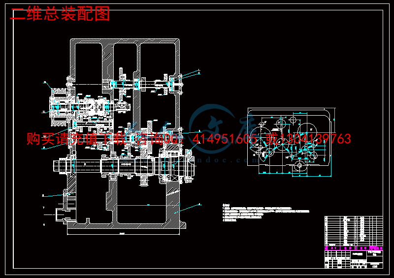
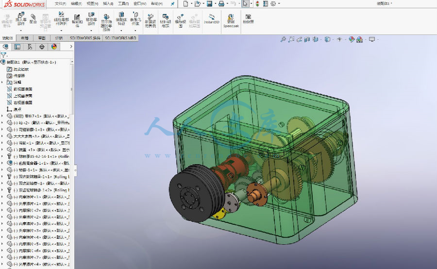
摘要:CA6140车床作为主要的车削加工机床,在机械加工行业中得到了普遍的应用。CA6140车床主轴箱的主要功用是支撑并且传动主轴,使车床的主轴带动工件用特定的转速转动。本次毕业设计运用计算、验算、实验等方法,确定了运动方案和实现结构优化设计,通过功能设计与计算,运用Solidworks三维软件完成了零部件的建模与装配、实现装配动态仿真。将CA6140车床主轴箱的内部结构以及工作原理,更生动形象的表达出来。 

关键词:CA6140机床主轴箱;建模与装配;三维结构设计;运动仿真


Three dimensional design and Simulation of the transmission of the CA6140 lathe main axle box


Abstract:The CA6140 lathe as the main turning processing machine tool, has been popular applied in the manufacturing industry. The main function of CA6140 lathe headstock is the support and transmission shaft, the lathe spindle drives the workpiece rotate with the prescribed speed. The design is based on the computation, analogy and experimental methods, completed to determine the motion scheme and structure design, the design and calculation, modeling and assembly, using Solidworks 3D software complete parts assembly,dynamic display. the internal structure of CA6140 lathe headstock and working principle, more vivid image expression。

Keywords: CA6140 machine; headstock; dimensional animation


目   录


摘要…………………………………………………………………………………………Ⅰ

Abstrat ……………………………………………………………………………………Ⅱ

目录…………………………………………………………………………………………Ⅲ

1  绪论..................................................................1

1.1 研究意义.............................................................1

1.2 研究现状.............................................................1

1.3 课题研究内容与方法...................................................1

1.4 设计方案可行性分析...................................................2

1.5 小结.................................................................2

2  总体设计方案..........................................................3

2.1 主轴箱的组成和特点...................................................3

2.2 主轴箱的主要参数.....................................................3

2.3 传动系统及其方案的确定...............................................4

3  车床主轴箱的设计计算..................................................6

3.1 主轴箱的箱体.........................................................6

3.2 Ⅰ轴主要零件设计计算.................................................7

3.3 Ⅱ轴主要零件设计计算................................................16

3.4 Ⅲ轴主要零件设计计算................................................22

3.5 Ⅳ轴主要零件设计计算................................................28

3.6 Ⅴ轴主要零件设计计算................................................31

3.7 Ⅵ轴主要零件设计计算................................................34

3.8 主轴箱的装配效果图..................................................36

3.9 小结................................................................39

4  车床主轴箱的运动仿真........................................................41

总结与展望.......................................................................43

致谢.............................................................................44

参考文献.........................................................................45


1 绪论

1.1 研究意义

车床的应用极为广泛,主要用于加工各种回转表面,其中 CA6140车床是卧式车床应用最广泛的一种。

    CA6140型普通车床的主要组成部件有:主轴箱、刀架、溜板箱、进给箱、尾架、床身等[1]。

1)检验理论知识:本次关于CA6140车床主轴箱的三维设计,对过去所学的机械设计专业理论知识进行了全面检验,在设计过程中发现自身在以前学习过程中所忽略和不会的部分,并进一步加强和学习。

2)完善理论知识:在完成本次毕业设计的过程中,发现了许多我从未学过的新知识,对新知识的学习,扩大了自己的知识面,完善了自己的基础理论知识。并且提高了自己对于三维设计软件(Solidworks)的使用能力、三维设计、三维建模的能力。

3)应用理论知识:在本次毕业设计过程中,应用所学的机械专业理论知识,对车床主轴箱做了外观和部分零部件尺寸方面的优化设计,并借助Solidwork三维软件,绘出主轴箱整体及其零部件的三维设计图,并且生成装配体效果图,直观的表现出调整后主轴箱的整体及零部件的外观、形状、尺寸及装配特点。

1.2 研究现状

传统的车床主轴箱设计方法比较复杂,尤其是在制造新零件时需制造模具和调整机床,有准备时间周期长,误差大,加工零件的精度很难达到标准要求等缺点,在设计过程中图纸和数据更改也比较费事,需要投入大量的时间和精力,如果使车床主轴箱的设计一开始从三维实体造型开始,整个产品的设计过程从草图,实体,装配,虚拟样机,都可以利用三维呈现出来。将大大减少了产品的设计过程时间,提高了开发设计效率,使产品变得更加形象、具体,更利于开发者的观察和修改。现在流行的三维软件Solidworks完全符合这个要求,为机械三维产品的设计提供了一种便捷的方式。


内容简介:
毕 业 设 计 任 务 书1毕业设计课题的任务和要求: 设计任务为了解车床主轴变速箱的结构和工作原理,使用三维CAD设计软件完成给定型号车床主轴变速箱的三维设计,绘制二维工程图,并实现车床主轴变速箱的运动仿真。2毕业设计课题的具体工作内容(包括原始数据、技术要求、工作要求等):(1)掌握三维CAD设计软件的使用技术; (2)完成给定型号主轴变速箱的三维建模;(3)用三维设计软件实现车床主轴变速箱的运动仿真;(4)绘出(或打印出)部分相关工程图; (5)撰写设计说明书: (a)设计合理,语句通顺,格式规范,图表正确,表述清晰; (b)打印成册。毕 业 设 计 任 务 书3对毕业设计课题成果的要求包括毕业设计、图纸、实物样品等):1 毕业设计开题报告一份;2 毕业设计说明书一本,要求思路清晰,语句通顺,无错别字;3 图纸一套,要求结构合理,表达正确、清晰。4毕业设计课题工作进度计划:起 迄 日 期工 作 内 容2016年2月29日 3月 21 日3月 22日 5月 20 日5月 20日 6月1日6月 1日 6月5日学习相关软件,查阅资料,撰写开题报告;熟悉开发环境,详细设计;撰写说明书;毕业答辩。学生所在系审查意见:同意下发任务书系主任: 2016年2 月29 日 译文标题基于工程数据库的起重机结构计算机辅助设计原文标题CAD/CAM OF CRANES STRUCTURE BASED ON ENGINEERING DATABASE作 者 Chonghua Wang译 名王重华国 籍中国原文出处Department of Mechanical Engineering Shanghai Maritime University P.R.China e-mail 译文:基于工程数据库的起重机结构计算机辅助设计摘要根据大型复杂结构机械CAD/CAM专业,根据起重机的结构工程数据库的CAD / CAM系统是本文提出的。基于自顶向下的层次结构,特征技术,装配约束关系,自下而上的装配工艺和向下到顶部尺寸约束关系,建立了一个三维参数化模型族的计算机辅助设计平台,允许生成可行的配置的起重机结构。一个总结的GUI和ANSYS的APDL图案的背景知识,起重机的有限元模型是基于组合模式的建立。实现了有限元模型的同步更新和分析。在系统中构建了2种工程数据库。一个是参数化的数据库,包含了各种参数化的零件和部件,常用于起重机结构。另一种是针对每一个单独的起重机而设计的,其中包括用于起重机结构的所有部件和部件,其中参数化的变量被确定的值所代替。以后可以用来创建BOM,建立有限元模型,安排零件在数控切割钢板,焊接和制造工艺装置设计。微软SQL服务器选择构建数据库和CADCAM集成是使用MS VC+ 6和Pro/TOOLKIT实现。关键词计算机辅助设计/凸轮,结构,起重机,工程数据库,三维设计1。在过去的几十年里,国际贸易迅速增长,这依赖于世界物流的运输链。深水港的能力,迅速处理和分发大量的集装箱和货物,这是在在物流链中不断发挥关键作用。现在世界上几乎所有的港口都在忙着扩张。港口起重机在最近几年迅速增长。港口起重机是非常大的,复杂的机器,越来越大,更自动化,更高的速度,以满足巨大的船舶和大量的负载和卸载。与一般的机器相比,它具有一个独特的组成部分,它是一个巨大且复杂的结构。起重机结构的计算机辅助设计/凸轮机构的特点是:起重机的结构型式和设计参数,满足各种不同的自然、环境和运行条件的设计参数。结构由几个部件组成。每一个部件都是由焊接而成的。虽然很多零件都是矩形板,但它们的厚度可以随构件的变化而不断变化,以减轻重量,同时保持足够的强度。此外,有大量的结构细节,让组件支持外部负载。因此,该组件是非常复杂的。C)的结构设计应符合强度、稳定性等要求,补偿的标准和规范,累积损伤和振动频率等。因此有必要对结构进行有限元分析。由于结构非常大,复杂,任何有限元软件包的商业计算机辅助设计软件是不够的,以处理复杂结构的起重机。起重机结构凸轮的技术比较简单。特别是数控切割和自动焊接在大多数工厂都有广泛的应用。本文提出了起重机结构的计算机辅助设计/计算机辅助设计。它主要是基于程序的计算机与参数化三维建模技术、有限元分析、工程数据库技术、Pro/E、ANSYS、MS Visual C+和微软SQL Server。该系统包括建立起重机械三维参数化模型族的计算机辅助设计平台,建立有限元模型,二次开发的三维参数化模型,同步更新和有限元分析,参数化和若干模型的构造和收集信息,组件和起重机的应用和供应平台。2。为了支持起重机设计的计算机辅助设计平台,设计了起重机的三维参数化模型,为每个家庭成员提供了一种可行的起重机、部件和部件的配置,然后将它们缩放到期望的尺寸。港口集装箱起重机计算机辅助设计模型平台的框架,为港口集装箱起重机提供支持功能:2.1。分解成零部件和零部件的基础上的自顶向下的层次结构的产品结构,能够方便的设计任务的开发团队的成员,一个起重机的设计必须以某种方式结构化。著名的层次结构的产品结构是用于此。起重机由若干部件组成。每个组件可以包含若干子或一部分。第一种类型的组件被称为复合组件(在下面的文本,我们只称之为组件),第二类是一个单一的组件(我们称之为下面的一部分)。该产品结构以这种方式持续下去,直到所有的组件在层次结构中的最低水平。因此,产品是结构化的自上而下的方式,创造尽可能多的层次,如所需的设计师。图1显示了一个简化的集装箱起重机的层次结构。2.2。构建了基于特征技术特征技术的CAD软件平台如Pro/Engineer提供的三维零件模型、SolidWorks等包括:a)草案的特点,基本几何特征绘制截面拉伸,旋转或扫描;b)附件的功能被添加到基本特征包括孔、圆角、塌角等。根据上述特征技术,生成集装箱起重机零件的三维模型。2.3。指定组件的空间约束关系,以创建产品种类的组件和组件之间的空间关系,在产品族中的代表使用装配约束关系。在计算机辅助设计软件的装配模块中,如支持/工程、装配等约束关系,如匹配、对准、插入和切向等。在这里,根据起重机的层次结构,零部件和组件之间的关系是建立使用装配约束提供的专业/工程师。图2表示门户框架中的组件之间的装配约束关系。2.4。为了使零件、零部件和起重机的设计参数发生改变时,为了使零件、部件和起重机的新的三维模型发生改变,从而建立起到顶部尺寸约束关系,从而建立零件或部件的设计参数。设计参数由设计人员根据零件或部件的结构设计。尺寸变量,这是自动生成时,三维模型的零件或组件,控制真正的几何尺寸和拓扑关系的一部分或一个组件。因此,为了使设计参数发生变化时,零件、部件或吊车的精确的新模型得到改变,应准确构造设计参数和尺寸变量之间的关系。商业计算机辅助设计软件,如专业/工程师提供的功能,建立设计参数和设计参数和尺寸变量之间的关系。必须指出的是,每一部分都将被用来组成一个组件。所有的引用而不是对部分实体将失效,必须重新开业。因此,重要的是要设置所有的参数的模型的一部分。2.5。部件或产品的装配约束关系的基础上,根据起重机的层次结构模型自下而上的方式产生的,一个设计师能尽快的任务已经分配给他开始建立零件三维模型。另一方面,三维建模组件设计器所获分配只能在其子组件和零件已创建启动。因此,实际的建模活动是自下而上的过程,从层次结构的产品结构的叶子开始。根据起重机的层次结构和组件和零件之间的装配约束关系,生成了零件的三维模型。对零件模型的参数进行评估,并在组装前进行修改一个组件。如果有必要修改部分后,它已被组装,应删除部分和一个新的模型的部分进行评估,以适当的价值和被组装。所有的设计参数必须在部件或组件的模型上设置。无设计参数是在系统中的起重机装配模型上设置,以避免在任何参数发生改变后,在整个起重机模型再生故障。图3显示了基于组件和零件之间的约束关系的繁荣的三维装配模型。图4和图5基于装配约束关系的子组件和零件之间不同的门户框架显示3D模型。3。有限元分析中的有限元分析模型的生成,数学模型应尽可能准确地模拟真实物体、载荷和约束条件,得到可靠的结果。在整个起重机结构上,应进行有限元分析。由于结构非常大,复杂,任何有限元软件包的商业计算机辅助设计软件是不够的,以满足任务。ANSYS是选中是因为其强大的分析功能。同样的道理,在ANSYS中不能采用板单元。Beam188单元的建立起重机有限元模型。在ANSYS中,两种建模模式提供了建立有限元模型,即人机交互模式也叫GUI模式和命令流输入模式也被称为APDL模式。双模式也有优点和缺点,这是在参考文献中描述。一个总结的GUI和ANSYS的APDL图案的背景知识,起重机的有限元模型是基于组合模式的建立。首先,对起重机有限元模型可以通过ANSYS的GUI模式构建。第二,CAE分析起重机进行相应的日志文件也产生。日志文件可以通过使用ANSYS APDL参数化设计语言所提供的一些变化后,已在部分修订,组件或起重机。该起重机包括生成模型的APDL,载荷和约束的施加,建立了有限元求解、后处理。生成的模型由参数定义、节点/单元/节建立有限元分析模型等新的起重机是通过运行APDL文件构造。实现了有限元模型的同步更新和分析。参见图6和7的有限元模型和应力分析图的起重机结构。4。数据库系统是为了管理起重机的设计与制造的所有信息,实现数据共享,由计算机辅助设计/凸轮集成系统的各个模块共享,使程序独立于数据,保证数据的完整性和安全性,必须采用数据库系统。在流行的数据库管理系统微机如FoxPro、Visual Foxpro、SQL Server等,微软SQL Server 2000是最后的选择。4.1。为了GDB和深发展加快设计,提高设计质量,减少重复工作,两种数据库是系统设计。一个被称为通用数据库(GDB)。其他特殊的数据库(SDB)个人起重机。GDB是一个参数化的数据库,包括各种参数化零件和常用的起重机结构组成。部件和组件被存储在多个分支和层次,作为一个树结构。虽然有可能是大量的矩形板的一个组成部分,例如,在繁荣,在梁,只有一个参数化的矩形板在每一个分支,以减少冗余。GDB可以被所有设计师的公司参观。当一个设计师给设计的一个组成部分,他可以先搜索gdb的相应部门利用现有的参数化零部件和组件的三维模型构建。同时,信息的零件和部件的使用记录在SDB。他可以修改在GDB的零部件如果他们稍有不同,从什么是需要的。他甚至可以创建一个新的参数化零件和组件并将它们保存到GDB的机关批准。SDB是专为每一个个体的起重机和包含所有零部件用于起重机结构。它们也存储在一个树结构中。不同于GDB,每一部分都有相应的记录,在深发展。参数化变量被确定值替换。随着这些,代码,名称,存储位置,位置,材料,重量,重心,制造等参数的参数。一些数据,例如重量的一部分,计算的一部分已被缩放。SDB可以用来创建BOM,建立有限元模型,安排零件在数控切割钢板,焊接和制造工艺装置设计。4.2。数据库结构与数据库的使用,一些一般性的问题将被解决:数据完整性:在一个文件系统中,设计师谁保存的文件的变化,然后删除由设计师谁保存的文件之后。但同时,采用数据库的交易机制,在同一时间,一个计算机辅助设计模型不能同时进行修改。直接关系:模型的数据实体的直接关系,三维模型之间的技术依赖关系可以很容易地发现。直接关系给设计者一个提示,在模型的改变之后,模型也必须改变。中心数据管理:数据中心库提供备份和版本控制的几个优点。数据聚类:数据的聚类速度的数据访问,因为每个设计师可以得到所需的信息,在他的本地PC。这是非常重要的分布式和协同设计项目。我们已经使用了实体关系(二)模型,这是一个流行的高层次的概念数据模型,设计数据库。这种模式及其变化经常被用于数据库应用程序的概念设计,和许多数据库设计工具采用其概念。二型模型描述数据的实体,关系和属性。二型代表是一个实体,它是现实世界中的一个独立存在的基本对象。每个实体都有属性,即描述它的特定属性。一个特定的实体将有一个值的每个属性。描述每个实体的属性值成为存储在数据库中的数据的一个重要部分。一个关系型R在n个实体类型E1,E2恩定义的关联或关系集从这些类型的实体之间的。实体类型和实体集的关系类型及其对应关系设置统称同名的R.根据起重机的层次结构,数据库具有实体。每一部分,组件和起重机可以被表示为一个实体,它具有设计参数描述的属性。在起重机产品零部件之间的空间关系表示为关系集R的数据库采用微软SQL Server和组件对象模型(COM)。5。CADCAM集成的基于Visual C+和SQL Server数据库管理系统作为管理工程数据库和Pro/ENGINEER用于建立三维模型,采用Visual C+作为编程语言构建计算机辅助设计/凸轮的整体系统。第一个原因是Visual C+是一个可以访问SQL数据库语言。其次,当我们设置GDB必须访问数据库以及访问的三维模型,利用Pro/TOOLKIT,这是第二利用Pro/ENGINEER提供的软件包。当我们处理的是深发展,我们也需要访问数据库和参数化模型的同时,做一些修改。Visual C+是强大的编译程序能访问Pro/Engineer和SQL Server 2000的同时,实现它们之间的数据通信。第三、Visual C+是一种面向对象的编程软件有许多优点。6。本文介绍了基于工程数据库的集装箱起重机结构计算机辅助设计/凸轮一体化系统的设计。基于自上而下的层次化的产品结构、特征技术、装配约束关系,利用Pro/ENGINEER提供的自底向上的装配工艺和尺寸关系到顶部,一个三维参数化模型的CAD平台的建立是为了让家庭的起重机的可行的配置生成。一个总结的GUI和ANSYS软件APDL图案的背景知识,基于复合模式建立了该桥的有限元模型。实现了有限元模型的同步更新和分析。利用微软SQL Server 2000,两种数据库是系统与CAD/CAM集成系统的各个模块进行设计。数据共享整个系统。以Visual C+的帮助下,实现了CADCAM的集成开发方法。该系统可以大大提高港口集装箱起重机结构设计效率和开发凸轮机械结构复杂的大型结构的应用提供一个平台。致谢本文受上海市重点学科建设项目,资助号:T0601。引用Chandrupatla, T., and Belegundu, A., (1991), Introduction to Finite Elements in Engineering, Prentice Hall. Claesson, A., Johannesson, H., and Gedell, S., (2001), Platform Product Development: Product Model a System Structure Composed of Configurable Components, Proc. 2001 ASME DETC/CIE Conference, Pittsburgh, ASME, New York, ASME Paper No. DETC2001/DTM-21714 Conner, C. G., De Kroon, J. P., and Mistree, F., (1999), A Product Variety Tradeoff Evaluation Method for a Family of Cordless Drill Transmissions, Proc. 1999 ASME DETC/CIE Conference, Las Vegas, ASME, New York, ASME Paper No. DETC99/DAC-8625. Martin, M. V., and Ishii, K., (2002), Design for Variety: Developing Standardized and Modularized Product Platform Architectures, Res. Eng. Des., 13(4),pp. 213235. Meyer, M. H., and Utterback, J. M., (1993), The Product Family and the Dynamics of Core Capability, Sloan Manage. Rev., 34(3), pp. 2947. Nayak, R. U., Chen, W., and Simpson, T. W., (2002), A Variation-Based Method for Product Family Design, Eng. Optimiz., 34(1), pp. 6581. Peak, R. S., (2003), Characterizing Fine-Grained Associatively Gaps: A Preliminary Study of CADCAE Model Inter-operability, Proc. 2003 ASME DETC/CIE Conference, Chicago, ASME Paper number CIE48232. Simpson, T. W., Maier, J. R. A., and Mistree, F., (2001), Product Platform Design: Method and Application, Res. Eng. Des., 13(1), pp. 222. Siddique, Z., and Rosen, D. W., (1999), Product Platform Design: A Graph Grammar Approach, Proc. 1999 ASME DETC/CIE Conference, Las Vegas, ASME, New York, ASME Paper No. DETC99/DTM-8762. Siddique, Z., and Rosen, D. W., (2001), On Discrete Design Spaces for the Configuration Design of Product Families , AI EDAM., 15(2), pp. 91108. Steffen, Dennis, Graham and Gary, (2004), Inside Pro/ENGINEER Wildfire, Thomson/Delmar Learning. VRML Consortium, (1997), The Virtual Reality Modeling Language: International Standard ISO/IEC DIS 14772-1. 原文:LathesCAD/CAM OF CRANES STRUCTURE BASED ON ENGINEERING DATABASEABSTRACT According to the specialties of CAD/CAM for largescale complex structures of machinery, a CAD/CAM system based on engineering database for cranes structures is proposed in this paper. Based on the top-down hierarchical product structure, feature technology, assembly constraint relationship, bottom-up assembly process and down-to-top dimension constraint relationship, a CAD platform of 3D parametric model family is built to allow generation of feasible configurations of crane structures. With a sum up of background knowledge of GUI and APDL patterns of ANSYS, the finite element model of the crane is set up based on composite pattern. Synchronous updating and analysis of FEA model are realized. Two kinds of engineering databases are constructed in the system. One is a parameterized database and contains all kinds of parameterized parts and components common used in crane structures. Another is designed for every individual crane and contains all parts and components used in crane structure, where parameterized variables are replaced by definite values. The later can be used to create BOM, to build FEM model, to arrange parts in the steel sheet for numerical control cutting and to design technological apparatus for welding and manufacture. Microsoft SQL Server is selected to construct the databases and the CAD/CAM integration is achieved using MS VC+6.0 and Pro/TOOLKIT. KEYWORDS CAD/CAM, Structure, Crane, Engineering database, 3D design 1. INTRODUCTION The international trades which increase rapidly in the last few decades rely on the transportation chains of world logistics. The abilities of the deepwater ports to swiftly handle and distribute the large quantity of containers and goods which are surging in continuously play a key role in the logistics chains. Almost all ports in the world are busy expanding nowadays. The port cranes increase rapidly all over the world in the recent years. The port cranes are very large and complex machines and becoming larger, more automatic and with higher speeds to meet the huge ships and the great quantity of load and unload. Comparing with normal machines, it has a unique component that is the huge and complicated structure. The characters of CAD/CAM for cranes structure are: a) Cranes structure has various types and a lot of design parameters to meet the different natural, environmental and operating conditions of every harbor. b) The structure is consisted of several components. Every component is formed by welding numerous parts. Although a lot of parts are rectangle plates, their thickness may vary continually along the component to reduce the weight while keeping enough strength. In addition, there are lots of construct details to let the component support external loads. So the components are very complicated. c) The design of the structure should conform to the requirements about strength, stability, bucking, cumulative damage and vibration frequency etc. of the Standards and Specifications. So it is necessary to do finite element analysis on the structure. As the structure is very large and complex, any FEA package of commercial CAD software is insufficient to handle the complex structures of crane. d) The techniques of CAM for crane structure are comparatively simple. Especially numerical control cutting and automatic welding are widely used in most factories. An integrated CAD/CAM for the cranes structure is proposed in this paper. It is mainly based on the technologies of parametric 3D modeling, finite element analysis, engineering database technique, Pro/ENGINEER, ANSYS, MS Visual C+ and Microsoft SQL Server. The system includes building CAD platform of 3D parametric model family for crane, setting up FEA model, the second exploiting of 3D parametric model, the synchronous updating and analysis of FEA, construction and collection information of parametric and certain models of parts, components and cranes and supply a platform to develop the application of CAM. 2. CAD PLATFORM OF 3D PARAMETRIC MODEL FAMILY FOR CRANE In order to support the designing of crane family, CAD representations for product platform is developed to allow generation of feasible configurations of cranes, components and parts for each family member and then scaling them to the desired size. The framework of CAD model platform for port container crane has to provide support functions listed as follows: 2.1. Decompose crane into components and parts based on top-down hierarchical product structure To be able to facilitate design tasks to the members of a development team, a crane to be designed has to be structured in some way. The well-known hierarchical product structure is used for this. A crane consists of a number of components. Each component can either consist of a number of subcomponents or be a part. The first type of component is called a compound component (in following text, we only call it as component), the second type a single component (we call it as part below). The product structuring continues recursively in this way, until all components at the lowest level in the hierarchy are parts. So the product is structured in a top-down way, creating as many levels as desired by the designers. Figure 1 shows a simplified hierarchical product structure of a container crane. 2.2. Construct 3D part model based on feature technology Feature technology provided by CAD software platform such as Pro/ENGINEER, Solidworks etc. includes: a)Draft features which are fundamental geometry characters produced by drawing cross sections and stretching, rotating or scanning them; b)Attachment features which are added to the fundamental characters include hole, round corner, collapse corner and so on. According to the feature technology describes above, the 3D models of the parts of the container crane are generated. 2.3. Specify spatial constraint relationships of components to create product variety The spatial relationships among the components and parts in the product family are represented using assembly constraint relationship. In the assembly module of CAD software such as Pro/ENGINEER, constraint relationships in assembling, for example, matching, aligning, inserting and tangential etc. are provided. Here, based on the hierarchical structure of crane, relationships among parts and components are built using the assembly constraints provide by Pro/ENGINEER. Figure 2 represents the assembly constraint relationships among the parts of portal frame. 2.4. Establishment of down to top size constraint relationship In order to regenerate the new 3D model of parts, components and crane when the values of design parameters are changed, a down to top size constraint relationships between size variables and design parameters in a part or component should be built. Design parameters are established by designers according to the structure of part or component. Size variables, which are generated automatically when 3D models of parts or components are built, control the real geometrical size and topological relationship of a part or a component. Therefore, in order to regenerated the accurate new model of a part, a component or crane when the values of design parameters are changed, the relationship between design parameters and size variables should be constructed accurately. Commercial CAD software such as Pro/ENGINEER has provided function to set up design parameters and build relationships between design parameters and size variables. It must be pointed out that every part would be used to compose a component. All the references which are not on the entity of the part would be invalidated then and must be setting up again. So it is important to setting all the references of parameters on the model of the part. 2.5. Generation of component or product assembly model based on constraint relationships in bottomup way Based on the hierarchical structure of the crane, a designer can start building 3D model of a part as soon as the task has been assigned to him. On the other hand, 3D modeling of a component by a designer to whom it was assigned can only start just after its subcomponents and parts have been created. So the actual modeling activity is bottom-up process, starting at the leaves of the hierarchical product structure. According to the hierarchical product structure of the crane and assembly constraint relationships among components and parts, 3D models of a component desired are generated. The parameters on the model of a part should be evaluated and can be modified before it is assembled to a component. If it is necessary to amend the part after it has been assembled, the part should be deleted and a new model of the part is evaluated to the proper values and to be assembled. All design parameters must be setting on the models for parts or components. No design parameter is setting on the assembling model of the crane in the system to avoid failure in regenerating the model of whole crane after any parameter has changed. Figure 3 shows the 3D assembly model of the boom based on constraint relationships among subcomponents and parts. Figure 4 and 5 show 3D models of different portal frames based on assembly constraint relationships among subcomponents and parts.3. GENERATION OF FEA MODEL FOR THE CRANE In finite element analysis, the mathematical model shall simulate the real object, loads and constraints as accurately as possible to get the reliable results. The FEA should usually be carried out on the whole crane structure. As the structures are very large and complex, any FEA package of commercial CAD software is insufficient to fulfill the task. The ANSYS is selected because of its powerful structural analysis functions. As the same reason, the plate elements in ANSYS could not be adopted. The beam188 elements are used to build the FEA model of the crane. In ANSYS, two modeling patterns are provided to build the FEA model, i.e. the human-machine interactive pattern also called GUI pattern and the command stream flow input pattern also known as APDL pattern. Two patterns have also advantages and shortcomings which are described in reference literature. With a sum up of background knowledge of GUI and APDL patterns of ANSYS, the FEA model of the crane is built based on composite pattern. First, FEA model of the crane can be built through ANSYS GUI pattern. Second, CAE analyses of the crane are carried out and corresponding log file is also generated. The log file can be amended by using parametric design language APDL provide by ANSYS after some changes have been made on the parts, components or crane. The APDL of the crane including generation of model, imposing of load and constraint, finite unit solution and post treatment is built. Generation of model consists of parameter definition, node/unit/section establishment etc. A new FEA model of the crane is constructed by running the APDL file. Synchronous updating and analysis of FEA model are realized. See Figure 6 and 7 for the FEA model and stress analysis chart of a crane structure.4. DATABASE SYSTEM In order to manage all the information about design and manufacture of crane, achieve the data to be shared by every module of CAD/CAM integration system, keep the programs independent from the data and guarantee the data integrality and security, the database system must be used. Among the popular database management systems for microcomputer such as FoxPro, Visual FoxPro, SQL Server and so on, Microsoft SQL Server 2000 is final selected. 4.1. GDB and SDB In order to speed up design, improve design quality and reduce repeat work, two kinds of databases are designed in the system. One is called general database (GDB). The others are special databases (SDB) for individual cranes. The GDB is a parameterized database and contains all kinds of parameterized parts and components common used in crane structures. The parts and components are stored in many branches and levels as a tree structure. Although there may be lots of rectangular plates in a component, for example, in the boom, in the girder,. There is only one parameterized rectangular plate in every branch to reduce redundancy. The GDB can be visited by all designers of the company. As soon as a designer is assigned to design a component, he can first search the corresponding branch of GDB to make use of the existing parameterized parts and components to building 3D model of the component. At the same time, the information of the parts and components used are recorded in the SDB. He can modify the parts and components in GDB if they are slightly different from what are needed. Even he can create a new parameterized part and component and save them into GDB with the approval of an authority.The SDB is designed for every individual crane and contains all parts and components used in crane structure. They are also stored in a tree structure. Different from GDB, every part has its corresponding record in SDB. Parameterized variables are replaced by definite values. Along with these, the code, name, location of storage, coordinates of location, parameters of material, weight, center of weight, parameters of manufacture etc. are recorded. Some data, for example weight of the part, are calculated as soon as the part has been scaled. The SDB can be used to create BOM, to build FEM model, to arrange parts in the steel sheet for numerical control cutting and to design technological apparatus for welding and manufacture. 4.2. Database structure With the use of database, some general problems would be addressed: Data integrity: On a file system, the changes of the designer who saves the file first are then deleted by the designer who saves the same file afterward. But a CAD model can not be amended by two designers at the same time by using the transaction mechanism of database. Direct relations: With direct relations of data entities of models, technical dependencies among 3D models can be easily found. Direct relations give the designer a hint to which models must also be changed after making the changes in a model. Center data management: The central data pool offers several advantages for backup and versioning. Data clustering: The data clustering speeds up the data access, since each designer can get the desired information on his local PC. This is quite important for distributed and collaborative design projects. We have used the Entity-Relationship (ER) model, which is a popular high-level conceptual data model, to design the database. This model and its variations are frequently used for the conceptual design of database applications, and many database design tools employ its concepts. The ER model describes data as entities, relationships and attributes. The basic object that the ER model represents is an entity, which is a thing in the real world with an independent existence. Each entity has attributes, namely, the particular properties that describe it. A particular entity will have a value for each of its attributes. The attribute values that describe each entity become a major part of the data stored in the database. A relationship type R among n entity types E1, E2 En defines set of associations or a relationship set among entities from these types. As entity types and entity sets, a relationship type and its corresponding relationship set are customarily referred to by the same name R. The database has entities according to the hierarchical product structure of the crane. Each part, component and the crane can be represented as an entity which has attributes described by its design parameters. Spatial relationships among the components and parts in the crane products are represented as relationship set R. The database is constructed using Microsoft SQL Server and Component Object Model (COM). 5. INTEGRATION OF CAD/CAM BASED ON VISUAL C+ As the SQL Server DBMS is selected to manage the engineering database and Pro/ENGINEER is used to build 3D models, Visual C+ is adopted to be the programming language to construct the integer system of CAD/CAM. The first reason is that Visual C+ is one of the languages which can visit SQL database. Second, when we are setting up GDB we must visit the database as well as to visit the 3D models by use of Pro/TOOLKIT, which is a second exploiting software kit provided by Pro/ENGINEER. When we are dealing with SDB, we need also to visit the database and the parameterized models simultaneously and do some modification. Visual C+ is powerful to compile the programmes which are able to visit Pro/ENGINEER and SQL Server 2000 simultaneously and to implement the data communication between them. Third, Visual C+ is a programme software of OOM which has a lot of advantages. 6. CONCLUSION The CAD/CAM integration system of container cranes structure based on engineering database is introduced in this paper. Based on the top-down hierarchical product structure, feature technology, assembly constraint relationship, bottom-up assembly process and downto-top dimension relationship provided by Pro/ENGINEER, a CAD platform of 3D parametric model family is built to allow ge
温馨提示:
1: 本站所有资源如无特殊说明,都需要本地电脑安装OFFICE2007和PDF阅读器。图纸软件为CAD,CAXA,PROE,UG,SolidWorks等.压缩文件请下载最新的WinRAR软件解压。
2: 本站的文档不包含任何第三方提供的附件图纸等,如果需要附件,请联系上传者。文件的所有权益归上传用户所有。
3.本站RAR压缩包中若带图纸,网页内容里面会有图纸预览,若没有图纸预览就没有图纸。
4. 未经权益所有人同意不得将文件中的内容挪作商业或盈利用途。
5. 人人文库网仅提供信息存储空间,仅对用户上传内容的表现方式做保护处理,对用户上传分享的文档内容本身不做任何修改或编辑,并不能对任何下载内容负责。
6. 下载文件中如有侵权或不适当内容,请与我们联系,我们立即纠正。
7. 本站不保证下载资源的准确性、安全性和完整性, 同时也不承担用户因使用这些下载资源对自己和他人造成任何形式的伤害或损失。
提示  人人文库网所有资源均是用户自行上传分享,仅供网友学习交流,未经上传用户书面授权,请勿作他用。
关于本文
本文标题:CA6140车床主轴箱变速器三维设计及仿真【三维SW】【6张CAD图纸+毕业论文全套资料】
链接地址:https://www.renrendoc.com/p-19506230.html

官方联系方式

2:不支持迅雷下载,请使用浏览器下载   
3:不支持QQ浏览器下载,请用其他浏览器   
4:下载后的文档和图纸-无水印   
5:文档经过压缩,下载后原文更清晰   
关于我们 - 网站声明 - 网站地图 - 资源地图 - 友情链接 - 网站客服 - 联系我们

网站客服QQ:2881952447     

copyright@ 2020-2025  renrendoc.com 人人文库版权所有   联系电话:400-852-1180

备案号:蜀ICP备2022000484号-2       经营许可证: 川B2-20220663       公网安备川公网安备: 51019002004831号

本站为文档C2C交易模式,即用户上传的文档直接被用户下载,本站只是中间服务平台,本站所有文档下载所得的收益归上传人(含作者)所有。人人文库网仅提供信息存储空间,仅对用户上传内容的表现方式做保护处理,对上载内容本身不做任何修改或编辑。若文档所含内容侵犯了您的版权或隐私,请立即通知人人文库网,我们立即给予删除!