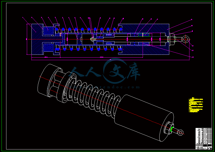
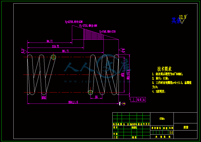
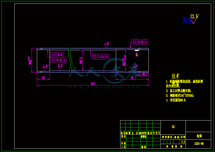
自供能式磁流变液减震器的结构设计及实验方案设计【含CAD图纸、说明书】
收藏
资源目录

压缩包内文档预览:
编号:23399533
类型:共享资源
大小:4.44MB
格式:ZIP
上传时间:2019-11-09
上传人:机****料
认证信息
个人认证
高**(实名认证)
河南
IP属地:河南
20
积分
- 关 键 词:
-
含CAD图纸、说明书
自供
能式磁
流变
减震器
结构设计
实验
方案设计
CAD
图纸
说明书
- 资源描述:
-
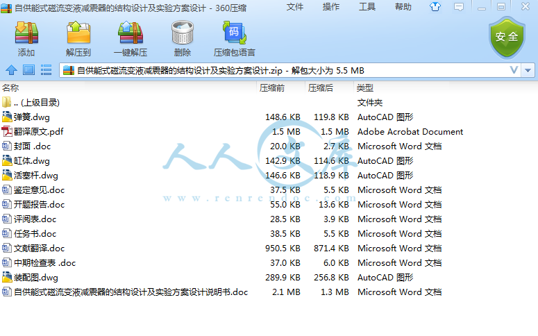
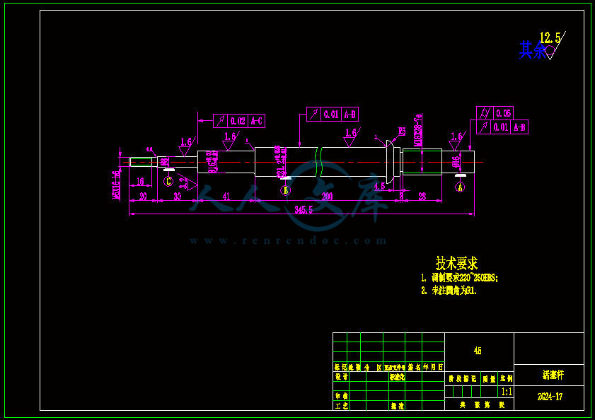
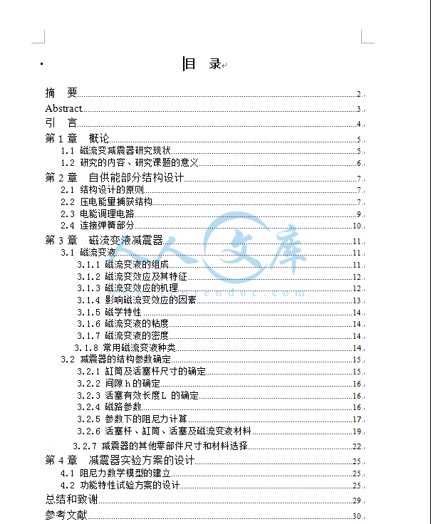
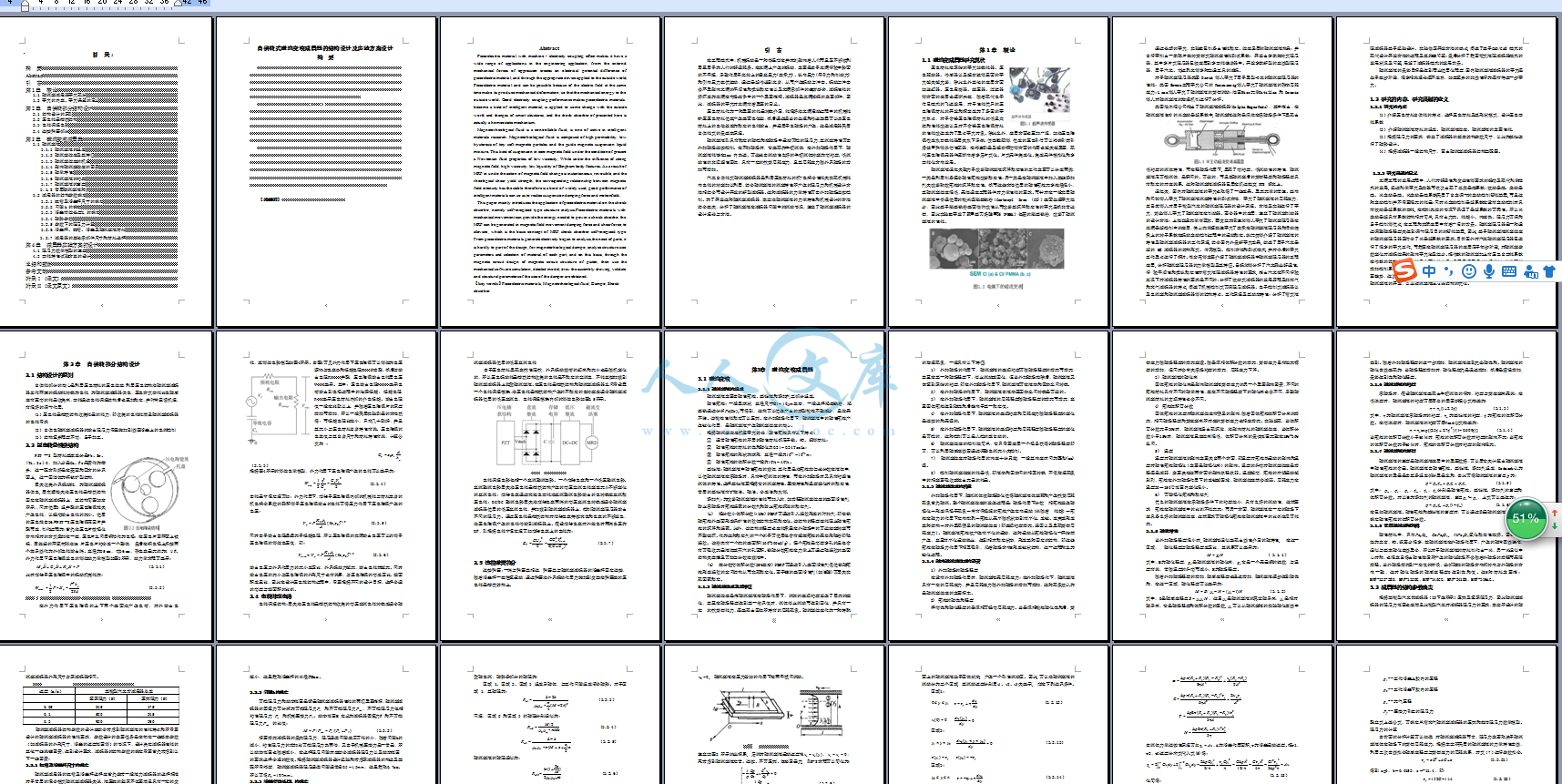
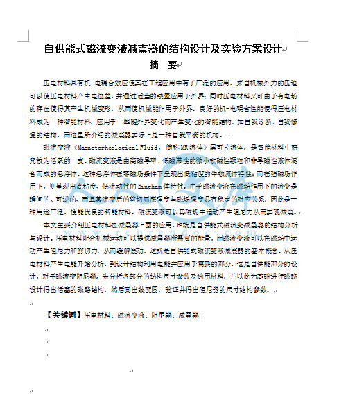
【温馨提示】压缩包内含CAD图有下方大图片预览,下拉即可直观呈现眼前查看、尽收眼底纵观。打包内容里dwg后缀的文件为CAD图,可编辑,无水印,高清图,压缩包内文档可直接点开预览,需要原稿请自助充值下载,所见才能所得,请见压缩包内的文件及下方预览,请细心查看有疑问可以咨询QQ:11970985或197216396
- 内容简介:
-
Smart electroresponsive droplets in microfluidicsJinbo Wu,aWeijia Wen*aand Ping Sheng*abReceived 4th June 2012, Accepted 26th August 2012DOI: 10.1039/c2sm26286jWe give a short review of droplet microfluidics with the emphasis on smart droplets, which are basedon materials that can be actively controlled and manipulated by external stimuli such as stress,temperature, pH, and electric field or magnetic field. In particular, the focus is on the generation andmanipulation of droplets that are based on the giant electrorheological fluid (GERF). We elaborate onthe preparation and characteristics of the GERF, the relevant microfluidics chip format, and thegeneration and control of droplets using GERF as either droplets or the carrier fluid. An importantapplication of the GERF droplets, in the realization of first universal microfluidic logic device whichcan execute the 16 Boolean logic operations, is detailed.I.IntroductionIn the late 1980s, at the 5thInternational Conference on Solid-State Sensors and Actuators, Manz and collaborators advancedthe concept1of total chemical analysis system (mTAS) thatemphasized the importance of microdevices in chemistry andbio-testing. Subsequently, this general concept has spawned adiverse field of investigation with descriptive terms such asmicrofluidics, bio-MEMS, lab-on-a-chip, etc. Microfluidics,in particular, relates to the new discipline involving the transportphenomena and fluid-based devices at the micron scale. In pastdecades, this area has undergone explosive development, servingas the common platform upon which engineers, physicists,chemists, biologists and others can interact and innovate on avast array of research directions and applications that rangefrom sensors, chemical/biological synthesis, microreactors, todrug discovery and point-of-care (POC) diagnostic.13Micro-fluidics technology has been employed in the development ofinkjet print-heads,4lab-on-a-chip technology,5microthermaltechnologies,6etc. There is great promise that microfluidicswould enable the integration of multiple steps of complexanalytical procedures, micro- to nanoliter consumption ofreagents/samples, as well as carrying out all the promisedprocesses with portability.79Atpresent,microfluidicstechnologyhastwodifferentapproaches: continuous flow microfluidics and droplet micro-fluidics. Both have their own special characteristics and appli-cations. Continuous flow microfluidics is more mature, dropletmicrofluidics is gaining recognition from its distinct micro-maneuverability and control.Continuous-flow devices offer fine-tuned control of flowcharacteristics, its scaling up is a challenge as the size of devicesJinbo WuJinbo Wus research interestsare focused on droplet-basedmicrofluidics, PCR biochip, andsurfacemodificationwithpatterning.Weijia WenWeijiaWensmainresearchinterests include soft condensedmatterphysics,electro-rheological (ER) and magneto-rheological (MR) fluids, field-induced pattern and structuretransitions, micro- and nano-fluidic controlling, microsphereand nanoparticle fabrications,thinfilmphysics,bandgapmaterials,metamaterialsandnonlinear optical materials.aDepartment of Physics, The Hong Kong University of Science andTechnology, Clear Water Bay, Kowloon, Hong Kong, China. E-mail:phwenust.hkbInstitute for Advanced Study, The Hong Kong University of Science andTechnology, Clear Water Bay, Kowloon, Hong Kong, China. E-mail:shengust.hkThis journal is The Royal Society of Chemistry 2012Soft MatterDynamic Article LinksC1 kV mm?1, the GERF exhibits solid-like behavior, e.g., the ability to transmit the shear stress. Themeasured dynamic shear stress of the sunflower oil-based GERFis comparable to that of the silicone oil-based GERF undersimilar electric fields. As the GERF has a much larger ERresponse under the same applied field (Fig. 2) compared with thetraditional ERF, a moderate electric field is sufficient for slowingdown or stopping the microfluidic flow, for both the dropletgeneration and manipulation processes. This is a crucial aspectthat has enabled the development of GERF-based smart dropletsin microfluidics.3.2Chip fabricationTo control the GERF droplets, electrodes have to be integratedinto the PDMS microfluidic chips. However, metal does notadhere well to the PDMS, owing to its low surface energy. Toovercome this problem, conductive particles such as carbonfibers/carbon black or Ag nanoparticles were embedded or addedinto PDMS, to form conducting composites that can becompatibly processed through soft lithography.114,115Two typesof PDMS-based conducting composites (silver/carbon PDMS Ag/C PDMS) have been developed by Niu et al.116Thesemixtures can be made into a thin film with desired thickness orpatterned into structures and embedded in PDMS microfluidicchips by soft-lithography. Planar and 3D conducting micro-structures, ranging from tens to hundreds of micrometers, havebeen successfully integrated into PDMS-based chips.By using the PDMS conducting composites, pairs of paralleland channel-wall-embedded electrodes canbe installed across themicrofluidic channel. With the input electric signal, electricalcontrol and sensing become achievable as part of GERF dropletcontrol. In particular, very small variations in the capacitancecan be detected when a droplet passes through between the twoelectrodes. Due to the electrodes design and feedback electroniccircuit, accurate real-time determination of size, shape andcomposition of droplets has been demonstrated (Fig. 3). Theoperational frequency can reach up to 10 kHz, a speed which isdifficult to be realized by conventional optical means. Thus, itcan be used in portable lab-chip for in situ detection and controlof droplets. The tested capacitance signals can be used directlyfor in situ labeling, sorting and droplet manipulation.3.3GERF as droplets or as a carrier fluidThere are two ways of applying the GERF into the microfluidicchannel for droplet manipulations. The first is to form GERFdroplets carried by another fluid, while the second is to useGERF as the carrier fluid to control other liquid droplets orbubbles. A schematic of the two cases is shown in Fig. 4(a) and(b). The electrodes placed on the sides of microfluidic channelscan apply the electric field to the flowing GERF, either in theform of droplets or as the carrier fluid. The electrodes atthe droplet generation section of the chip are located near thejunction area so as to control the timing of the GERF flow,thereby giving control to the generation of droplets. Down-stream electrodes provide further flow control in the form ofsensing, routing, and/or sorting.Fig. 2Calibration of the ER effect for two sunflower oil-based GERFwith nanoparticle concentrations of 20% and 40%. The dynamic shearstress is plotted as a function of time. 1 kV to 5 kV square wave DCvoltage pulses were applied to the sample across a 1 mm gap.113Fig. 3(a) Optical image of a group of DI water droplets with differentsizes. A small amount of dyes (without causing detectable variation of thedielectric constant for the droplets) was added for labeling. The detectedsignalsaredepictedin (b).(c)Detectedsignalswitharrowspointingto thecorresponding droplets: dyed DI water (dark) and ethylene glycol(light).117Soft MatterThis journal is The Royal Society of Chemistry 2012Downloaded by HK University of Science and Technology on 17 September 2012Published on 14 September 2012 on | doi:10.1039/C2SM26286JView OnlineBelow we review the two cases of GERF as droplets or as acarrier fluid, and their respective capabilities.3.3.1GERF smart droplet generation. In the first approach,GERF droplets are generated by the flow-focusing approach asshown schematically in Fig. 4(a). When the voltage on a pair ofelectrodes at the droplet generation section is set to zero, GERFdroplets can be generated in a passive manner. Inset (b) of Fig. 5shows mono-dispersed droplet generation when the flow rate ofGERF is at 0.2 ml h?1and the ratio of silicone oil (as the carrierfluid) to GERF flow is 3 : 1. However, when the flow rate is high(4 ml h?1) and the oil ratio is increased to 10 : 1 (see inset (c), thegenerated GERF droplets have a much higher poly-dispersity.GERF droplets also can be generated in an active scheme byapplying a square wave pulsed electric field signal on this pair ofelectrodes. Very uniform dropletsstable over a wider range offlow ratesare shown in Fig. 5(d, e). The period T of the elec-trical pulse is noted to be a critical parameter for stable GERFdroplet production. In particular, instability sets in when T isbeyond a certain working range that has been determined torange from 100 ms to 1000 ms, at a flow rate of GERF 0.4 mlh?1. By using two or more independent GERF inlets, bothoperating in the stable regime, GERF droplet synchronizationand relative phase variation can be easily achieved. The gener-ated droplet length is plotted as a function of T in Fig. 5(a) forfour flow rates. Moreover, the electric signals need not be peri-odic. Arbitrary pulse trains can be used to generate GERFdroplet chains with desired droplet size and distance. Twoexamples are shown in Fig. 5(f). In all cases droplet generationand the applied electric signal are well matched, i.e., the GERFdroplet chains are encoded by the electric signal. In the case ofthe thermal responsive smart material, Murshed et al. havedemonstrated temperature dependence of nanofluid droplet sizeduring the generation process,77while Seiffert et al. have shownthat the droplet (microgel capsule) size can also vary as a func-tion of temperature, from 60 mm to 120 mm after generation.793.3.2Flow control with GERF smart droplets. Fig. 6 showstwo types of GERF smart droplets generated with two differentnanoparticle concentrations. The top three panels, Fig. 6(a)(c)pertain to droplets with 40 wt% nanoparticles, whereas Fig. 6(d)is for GERF droplets with a lower percentage, 5 wt%, of nano-particles. Fig. 6(a) shows a smart droplet with no electric fieldapplied. It has a spherical shape. In Fig. 6(b), when an electricfield (1500 V mm?1) is applied, the droplet is seen to be elongatedwith the two ends touching the electrodes. This would slow downor even stop the motion of this droplet. When the field isremoved, the droplet resumed its original spherical shape andmoved on again, as shown in Fig. 6(c). To observe the encap-sulated GER particles more clearly, deformation of several smartdroplets with a lower nanoparticle concentration is shown inFig. 6(d). The droplet on the left is outside the influence of theelectric field, and it has a spherical shape. But for those under anapplied electric field, every droplet is stretched, accompanied bythe clearly visible separation of the nanoparticles from thesunflower oil. In particular, the chains/columns formed by thenanoparticles are plainly identifiable, and the sunflower oil isseen to be pushed forward to form a curved front with the sili-cone oil, owing to the differential pressure generated by theslowed channel flow.Fig. 6(e) shows the measured differential pressure DP P1?P2sustained by the GERF droplets at two different nanoparticleconcentrations. It is seen that the increase in the differentialpressure displays a nonlinear behavior, with saturation at ahigher electric field strength that is different from the near-lineardependence of the dynamic shear stress. Detailed inspection ofthe second inset in Fig. 6(e) reveals that the particles have lessdensity close to the channel wall than in the middle. However, themaximum differential pressure is more than 90 kPa mm?1for theGERF fluid with 40 wt% nanoparticles. Such a differentialpressure is adequate for most of the microfluidic applications.119The differential pressure induced by the smart droplets can beadjusted readily by varying the strength of the electric field,droplet size and nanoparticle concentration in the GERF.3.3.3Micro droplet display by GERF smart droplets. As bothGERF droplet generation and flow can be controlled, a micro-fluidic chip with integrated function of droplet encoding, sorting,storage and other manipulations may be achieved. Shown inFig. 5(a) Smart droplet generation under different GERF flow rates,with droplet length (normalized by flow rate) plotted as a function of theperiod T of the electrical controlsignals.113(f) Optical microscopic imagesof two groups of GERF droplets generated by control electrical signals(red line).Fig. 4Schematic view of the GERF as (a) droplets113and (b) the carrierfluid118in the microfluidic channels.This journal is The Royal Society of Chemistry 2012Soft MatterDownloaded by HK University of Science and Technology on 17 September 2012Published on 14 September 2012 on | doi:10.1039/C2SM26286JView OnlineFig. 7(a) is a schematic illustration of a designed chip to realizesuch functions. Three downstream channels are used to store thesmart droplets so as to form a display panel with the desiredcharacteristics. An example for displaying the character H isillustrated in Fig. 7(a). Fig. 7(b) shows the resulting display withthe characters HKUST clearly visible.By injecting smart droplets among the water droplet trains,packages of any desired number of water droplets can besandwiched between two smart GERF droplets. Fig. 7(c) showsthe schematic illustration for one part of such a chip (left) andsome snapshots of the experimental results (right). The injectionfrequency and phase (relative to the water droplets) of the smartdroplets are adjusted so that one smart droplet leads the train ofwater droplets.In this context it should be noted that in a similar fashion butby using magnetic field control, Sun et al. have demonstratedthat a small ferrofluid plug can be driven by an external magnetalong a circular microchannel, for the purpose of circulating thepolymer chain reaction (PCR) mixture through 3 temperaturezones.85By controlling the smart droplets, the train of water dropletscan be directed, sorted and delivered to a targeted destinationinside the chip, where mixing, heating and/or other processingmay becarriedout.Allsuch controls can bedigitallyprogrammed.3.3.4Droplets generation with GERF as the carrier fluid. Inthe second approach, GERF is used as the carrier fluid. Thedroplet generation control is illustrated in Fig. 4(b). Similar tothe first method, two pairs of electrodes located at the generationsection of the chip are used to apply the electric signals to controlthe droplet generation. Any fluid, which is immiscible with thesunflower oil, can be converted into desired droplets by thismethod. Examples of the droplet fluid include oil, water or evengas. Dyed deionized water was used for demonstration. Fig. 8shows the effect of the frequency of the applied electric signals atdifferent injection rates for both the flow-focusing and T-junc-tion droplet generation structures. The left upper insets ofFig. 8(a) and (b) are optical images of droplet profiles generatedwith the flow-focusing and T-junction structures, respectively.They have been carried out at a fixed flow rate without theelectrical control signals. It should be noted that, without theapplication of control signals the water droplet size is determinedby the relative flow rates between the GERF stream and thewater stream. This is denoted as the passive droplets generationregime. On this basis, water droplets with tunable sizes may beobtained through the active control of the GERF stream.As a function of applied electrical signals frequency, a stablegeneration regime is found within which water droplet genera-tion may be actively tuned by varying the frequency of theapplied electric field. A one-to-one correspondence between thefrequency of the applied control signal and the rate of dropletgeneration can be established. In Fig. 8, the stable dropletgeneration regime is delineated by the grey area in thefrequencyflow rate map. For the flow-focusing structure, ifthe flow rates of water and GERF are both fixed at 0.1 ml h?1,the generation rate of droplets may be varied from 7 to 17droplets per second by tuning the electrical signal frequency.This is indicated by a dashed line in Fig. 8(a). From the opticalimages, one can observe that in the stable regime, uniformdroplets train can be generated.Fig.6(a)(c)Opticalimagesof aGERFdropletdeformedbyanappliedelectric field and restored when the field is removed. (d) A sequence ofGERF particles under an applied electric field. Phase separation insidethe GERF particle is clearly seen. (e) Differential pressure generated bythe GERF droplets under different electric fields, for two differentnanoparticle concentrations in the GERF.113Fig. 7(a) Flow chart and control circuit for the generation of a smartdroplet display. (b) Optical images of the smart droplet display. (c) Asketch (left) of the chip component showing the orthogonal channels toform the water droplet packages, and optical images (right) of thegenerated packages formed with different numbers of water (red) drop-lets sandwiched between two GERF smart (black) droplets.113Soft MatterThis journal is The Royal Society of Chemistry 2012Downloaded by HK University of Science and Technology on 17 September 2012Published on 14 September 2012 on | doi:10.1039/C2SM26286JView OnlineBeyond the stable regime the droplets generation is charac-terized by irregularly spaced droplets of different sizes. FromFig. 8(a) and (b), we conclude that for both the flow-focusing andT-junction structures the droplet generation rate and the dropletsize can be easily tuned by external electric signals. This isdenoted as the active droplet generation approach.By using a similar flow-focusing generation device as describedabove, the control of gas bubbles (such as N2bubbles) has alsobeen demonstrated (Fig. 9 (a)(c).It is observed that the droplet generation and the appliedelectric signal are well matched, and the bubble chain can beencoded by the electric signal. Alternatively, since the GERF iselectrically controllable, the bubble generation can be digitallycontrolled by applied electric signals without changing the gaspressure. Bubble generation control is an interesting topic espe-cially in digital microfluidics, and it is also very useful for theapplication in bio-systems. The manipulation of bubbles isgenerally much more difficult, owing to their different charac-teristics compared to the liquid droplets. Nevertheless, thebubble size, flow direction as well as separation distance betweenthe bubbles can be easily controlled with this approach.3.3.5Multi-dropletsmanipulationanddropletsorderexchange. By using electrical signals and GERF, not only thedroplets generation process, but also the phase of two or moretypes of the generated droplets, can be controlled. Fig. 10 showstwo kinds of droplets generated in the same phase or oppositephase in the main channel. In Fig. 10(a), two types of droplets,dyed red and green, are generated with electrical pulsed signalsthat are in phase. Uniform pairs of droplets are seen. InFig. 10(b) we show the same two types of droplets generated withcontrol signals that are out of phase with each other. In this casethere is no pairing. Also shown in Fig. 10(c) is the work of Linket al.,120who applied the electric field on the droplet generationprocess in order to induce droplet formation. The phase of thedroplet break-off can be adjusted within the production cycle,accomplished by increasing the electric field above the criticalbreak-off field only at the instant when the droplet is required.Once generated, droplets can be encoded and stored, asdescribed above. Here we illustrate the use of flow rate anddirectional control to switch the ordering(s) in a train of droplets.Consider a train of different droplets as a coded message.Switching the order of the droplets implies the ability to revise orcorrect the message.The experimental setup and control mechanism are shown onthe left panel of Fig. 11, where two droplets, the blue one (dropletA) and the orange one (droplet B) come into the main channelFig. 8Frequency of droplet generation using two different structures,plotted as a function of the flow rate Q. The stable region is denoted bygrey.118The flow focusing geometry is shown in (a) and T-junction in (b).The dashed lines in (a) are intended to delineate the upper and lowerbounds of the generation frequency for stable droplet generation, at Q 0.1 ml h?1.Fig. 9(ac) Optical images of N2bubbles generated under different gaspressures but at the same flow rate of the carrier fluid. No electricalcontrol signal is applied. (df) Bubble generationunder the same pressureand flow rate, but with different coded electrical signals (indicated by theblue solid lines).118Fig. 10(ab) Controlled generation of two types of water droplets: (a)with the same phase of the control signals and (b) with the opposite phaseof the control signals.118(ce) Electrical control for two types of dropletsgeneration.120(c) Droplets having opposite signs of electrostatic chargecan be generated by applying a voltage across two aqueous streams. (d)The droplet is independently generated without an applied electric field.Each nozzle produces a different-sized droplet at a different frequencywith same infusion rates at both nozzles. Droplets do not coalesce. (e)With an applied electric field, the droplets break off simultaneously fromthe two nozzles with the same phase. Droplets coalesce.This journal is The Royal Society of Chemistry 2012Soft MatterDownloaded by HK University of Science and Technology on 17 September 2012Published on 14 September 2012 on | doi:10.1039/C2SM26286JView Onlinefrom the upstream, separated by a certain distance. By properlycontrolling the onoff duration of the applied voltages on elec-trodes 7 and 8, droplets A and B would resume their motion intothe downstream with the ordering reversed. Thus ordering andseparation distance between the droplets can be adjusted inaccordance to ones demand. Such maneuverability may be veryuseful in droplet control for bio-systems and microfluidiccomputing.IV.Microfluidic logic gateThe operation of complex microfluidic chips may eventuallyrequire extensive logic processes. While electronic logic gate canbe extremely fast, to implement the logic operations on amicrofluidic chip would require interfaces and additionalcontrols. Microfluidic logic gate is envisioned to minimizeexternal interfaces so as to enable the self-sustained execution ofcomplex microfluidic operations.To make the droplet control more automatic, the traditionalelectrical switch controlling the GERFs ONOFF flow is sup-plemented by the conductive droplet/dielectric carrier fluidflowing in a nearby channel. The context of inputs is extendedfrom the electric signal to droplet switches, i.e., the sequence ofdroplets in the carrier fluid that can be sensed owing to thedifferent dielectric constant or conductivity. To further elaborateon this point, we observe that as the designed electrodes areembedded on the sides of the microfluidic channels, the fluidchannels (either the droplets or the carrier fluid) may be viewedas elements of the electric circuit, i.e., as capacitance and/orresistance. When a droplet goes through a pair of electrodes, theelectric properties between the electrodes will be changed, andthe voltage is therefore re-distributed in the electrical circuit.These electrical signals can be used to trigger operations on thedroplets of the nearby fluid channel. In this fashion, the smartdroplets can communicate with each other, and the logicoperation can be carried out as a consequence. Furthermore,cascade connections and large-scale integration are possible.4.1Principle and device formatBy definition, a logic gate is an idealized or physical deviceimplementing a Boolean function, that is, it performs a logicaloperation on one or more logic inputs and produces a single logicoutput.121For an input of 2 variables, there are 16 possibleBoolean algebraic functions. A schematic illustration of amicrofluidic logic gate is shown in Fig. 12(a). Here the GERF isdenoted by the orange color, and green color denotes the signalelectrolytic droplet fluid, which is conducting. The insulatingcarrier fluid is denoted by the light yellow color. The conductingAgPDMS composite is shown in grey. The fluid channels andpads are electrically connected via the conducting strips. Withtwo parallel capacitances (top, near pads 1 and 2), the voltage onthe output GERF channel, |VA? VB|, can be manipulated underdifferent input combinations of V1, V2, V3, and V4. Since the flowof GERF can be stopped by a voltage |VA? VB| that exceeds athreshold value VC, this nonlinear characteristic serves as theenabling element for all the logic gate operations.To effectively control the voltage on the GERF outputchannel, we have purposely made the parallel capacitances of theinput signal GERF channels to have the same width and elec-trode sizes as the output control GERF channel. Thus theimpedances of all three GERF channels are the same and equalto a constant ZE. Therefore if the green (conducting) signaldroplets are absent in the gap regions of channels A and B, thenV1and V2would have very little effect on VAor VBsince they areseparated by the insulating (yellow) carrier fluid. In that case V3and V4control the value of |VA? VB|.The situation changes when there is a (green) signal droplet ineither gap A or gap B. When that happens, the conducting signaldroplet would make the applied voltage V1or V2to be the sameas VAor VB, respectively.For the configuration as shown in Fig. 12(a), the voltage on thecontrol GERF (central channel) can be expressed in general asVGERF |VA? VB| f(V1,V2,V3,V4,ZA(XA),ZB(XB),(1)where VAand VBare the electric potentials on either sides of theoutput GERF channel; V1to V4are the voltages applied to pads5, 6, 1, 2, respectively; ZA(XA) and ZB(XB) are the impedancesprovided by the signal channels A and B, respectively. HereXi 1 (i A or i B) indicates that a (green) signal droplet ispresent between the signal electrodes, and Xi 0 indicates thatonly the carrier fluid is present between the electrodes.As an example, if the signals are carried by the KCl droplets insilicone oil, the conductive KCl droplets serve as the triggersignals/switches (RKCl? 0 U and Roil? N). In this particularcase, voltage on the GERF output channel (central channel)should beFig. 11Flow chart and control circuit for the droplet order exchangeoperation. The right insets are optical images taken at different timesduring the droplets exchange process.118Fig. 12(a) Schematic illustration of a logic gate. (b) Cartoon ofuniversal logic gates implementation. (c) Optical image of the universallogic gate chip with all the channels are filled with blue-dyed DI water forbetter visualization.122Soft MatterThis journal is The Royal Society of Chemistry 2012Downloaded by HK University of Science and Technology on 17 September 2012Published on 14 September 2012 on | doi:10.1039/C2SM26286JView OnlineVGERF fXA;XB 8:f0;0 13jV4?V3jf0;1 12jV3?V2jf1;0 12jV4?V1jf1;1 12jV1?V2j:(2)Assuming VCto be the critical value required for GERFsolidification, we can set a V0such that 2/3VC V0$ 1/2VC, andthe corresponding input voltage combination for 16 possiblelogic functions can be generated.4.2Universal logic with 16 Boolean logic operationsThe implementation configuration of the microfluidic universallogic gate is shown in Fig. 12(b). The experimental testing results,as expected, show that all of the 16 Boolean logic operations canbe effectively executed in this microfluidic chip,122the size ofwhich is compared with that of a coin (Fig. 12(c). This is the firstmicrofluidic universal logic device in which all 16 Boolean logicoperations (according to two inputs) can be realized. As there are4 combinations of input signals (droplet status presented in theelectrodes) from the A and B channels, (XA, XB) (0, 0), (0, 1),(1, 0) and (1, 1) for each logic operation, there can be a total of64 experimental results. Four logic operations can be mergedinto their mirrored ones (such as A / B into B / A and IF Binto IF A), thus there are 48 independent configurations in total.GERF droplets in this device are noted to serve not only as thefluidic logic output, but also as part of the electrical circuit and,most importantly, as a nonlinear electro-mechanical element forfluidic control. An output GERF droplet can be further utilizedto provide the mechanical actuating/braking function, or forcontrolling/generating a third stream of signal fluid.TheGERF-basedmicrofluidiclogicchipshavechip-embedded electrodes that can serve as data-exchanging interfaceswith external devices such as oscilloscopes or PCs, therebypromising easy reprogramming and seamless integration withother devices. A real microfluidic droplet processor shouldresemble a CPU that can be smart enough to think bythemselves,28with outputs fully dependent on inputs in assignedtasks. However, unlike electronic devices, traditional integratedmicrofluidic circuits are constrained by the fabrication processbecause they are designed within pre-shaped architectures forgiven tasks, with a lack of reprogrammability or cascadability.123In the present smart GERF droplet system, all functions of theuniversal logic gate can be realized in one fluidic configuration,requiring only the adjustment of voltage inputs, and these logicfunctions can be further coupled to complex tasks with ease.V.Concluding remarksWe have given a short review of smart droplet microfluidics, withthe focus on the electroresponsive smart droplets. In particular,GERF, comprising dielectric GER nanoparticles suspended insunflower oil, is shown to be a versatile nonlinear electricalmechanical interface in microfluidics. By being able to inducehigh differential pressure under applied voltage, GERF enablesthe control and manipulation of droplets in microfluidics. Byusing the GERF as part of the electrical circuit, logic functionsmay be realized through electric communication with neigh-boring microfluidic channels. As this logic gate has a universalstructure for all the logic operations, its large-scale integrationrequires only structural repetition of identical units. Systemreprogramming, similarly, requires only the rearrangement ofvoltage inputs. The generated GERF droplets can be used eitheras an indicator of the chronological order of the signal droplets,or as the control of downstream manipulation, such as the mergeof droplets for chemical reactions. Meanwhile, the aforemen-tioned GERF-actuated microfluidic valve, mixer, pump, storage,display, droplet phase modulator and logic gate functionalitiesare all compatible with each other. Combined with these func-tions in microfluidic chips, multi-step reactions and biologicaltesting in microfluidic chips may be achieved with minimalexternal control.Notes and references1 A. Manz, N. Graber and H. M. Widmer, Sens. Actuators B, 1990, 1,244248.2 P. S. Dittrich and A. Manz, Nat. Rev. Drug Discovery, 2006, 5, 210218.3 V. Linder, Analyst, 2007, 132, 11861192.4 H. Seitzand J. Heinz,J. Micromech. Microeng.,2004,14,11401147.5 D. J. Harrison, K. Fluri, K. Seiler, Z. Fan, C. S. Effenhauser andA. Manz, Science, 1993, 261, 895897.6 M. K. Jensen, Y. Peles, A. Kos xar and C.-J. Kuo, Microfluid.Nanofluid., 2006, 2, 387397.7 P. Fortina, S. Surrey and L. J. Kricka, Trends Mol. Med., 2002, 8,264266.8 K. K. Jain, Cambridge Healthtech Inst. Third Annu. Conf. Lab-on-a-chip and Microarrays, 2001, 2, pp. 7377.9 L. J. Kricka, Clin. Chim. Acta, 2001, 307, 219223.10 S.-Y. Teh, R. Lin, L.-H. HungandA. P. Lee, Lab Chip,2008, 8, 198220.11 J.Clausell-Tormos,D.Lieber,J.-C.Baret,A.El-Harrak,O. J. Miller, L. Frenz, J. Blouwolff, K. J. Humphry, S. K oster,H.Duan,C.Holtze,D.A.Weitz,A.D.GriffithsandC. A. Merten, Chem. Biol., 2008, 15, 427437.12 W. Shi, J. Qin, N. Ye and B. Lin, Lab Chip, 2008, 8, 14321435.13 M. Chabert and J.-L. Viovy, Proc. Natl. Acad. Sci. U. S. A., 2008,105, 31913196.14 M. He, J. S. Edgar, G. D. M. Jeffries, R. M. Lorenz, J. P. Shelby andD. T. Chiu, Anal. Chem., 2005, 77, 15391544.15 M. M. Kiss, L. Ortoleva-Donnelly, N. Reginald Beer, J. Warner,C. G. Bailey, B. W. Colston, J. M. Rothberg, D. R. Link andJ. H. Leamon, Anal. Chem., 2008, 80, 89758981.16 H. Song, J. D. Tice and R. F. Ismagilov, Angew. Chem., Int. Ed.,2003, 42, 768772.17 M. R. Bringer, C. J. Gerdts, H. Song, J. D. Tice and R. F. Ismagilov,Philos. Trans. R. Soc., A, 2004, 362, 10871104.18 S. L. Anna, N. Bontoux and H. A. Stone, Appl. Phys. Lett., 2003, 82,364366.19 M. A. Burns, B. N. Johnson, S. N. Brahmasandra, K. Handique,J. R. Webster, M. Krishnan, T. S. Sammarco, P. M. Man,D. Jones, D. Heldsinger, C. H. Mastrangelo and D. T. Burke,Science, 1998, 282, 484487.20 A. Huebner, M. Srisa-Art, D. Holt, C. Abell, F. Hollfelder,A. J. DeMello and J. B. Edel, Chem. Commun., 2007, 12181220.21 B. Zheng, J. D. Tice, L. S. Roach and R. F. Ismagilov, Angew.Chem., Int. Ed., 2004, 43, 25082511.22 B. Zheng, J. D. Tice and R. F. Ismagilov, Anal. Chem., 2004, 76,49774982.23 B. Zheng, L. S. Roach and R. F. Ismagilov, J. Am. Chem. Soc., 2003,125, 1117011171.24 V. Linder, S. K. Sia and G. M. Whitesides, Anal. Chem., 2005, 77,6471.25 A. Imhof and D. J. Pine, Nature, 1997, 389, 948951.This journal is The Royal Society of Chemistry 2012Soft MatterDownloaded by HK University of Science and Technology on 17 September 2012Published on 14 September 2012 on | doi:10.1039/C2SM26286JView Online26 I. Shestopalov, J. D. Tice and R. F. Ismagilov, Lab Chip, 2004, 4,316321.27 N.-N. Nguyen, S. Lassemono, F. A. Chollet and C. Yang, IEEProc.: Nanobiotechnol., 2006, 153, 102106.28 I. R. Epstein, Science, 2007, 315, 775776.29 V. Srinivasan, V. K. Pamula and R. B. Fair, Lab Chip, 2004, 4, 310315.30 A. J. T udos, G. A. J. Besselink and R. B. M. Schasfoort, Lab Chip,2001, 1, 8395.31 D. Belder, Angew. Chem., Int. Ed., 2005, 44, 35213522.32 K. Jensen and A. Lee, Lab Chip, 2004, 4, 31N32N.33 P. Garstecki, A. M. Ga n? an-Calvo and G. M. Whitesides, Bull. Pol.Acad. Sci.: Tech. Sci., 2005, 53, 361372.34 S. Peng, M. Zhang, X. Niu, W. Wen, P. Sheng, Z. Liu and J. Shi,Appl. Phys. Lett., 2008, 92, 012108.35 Z. Nie, S. Xu, M. Seo, P. C. Lewis and E. Kumacheva, J. Am. Chem.Soc., 2005, 127, 80588063.36 H. C. Shum, J. Varnell and D. A. Weitz, Biomicrofluidics, 2012, 6,012808.37 T. Nisisako, T. Torii and T. Higuchi, Chem. Eng. J., 2004, 101, 2329.38 R. K. Shah, H. C. Shum, A. C. Rowat, D. Lee, J. J. Agresti,A. S. Utada, L.-Y. Chu, J.-W. Kim, A. Fernandez-Nieves,C. J. Martinez and D. A. Weitz, Mater. Today, 2008, 11, 1827.39 A. R. Abate and D. A. Weitz, Small, 2009, 5, 20302032.40 J. J. Agresti, E. Antipov, A. R. Abate, K. Ahn, A. C. Rowat,J.-C. Baret, M. Marquez, A. M. Klibanov, A. D. Griffiths andD. A. Weitz, Proc. Natl. Acad. Sci. U. S. A., 2010, 107, 40044009.41 T. Thorsen, R. W. Roberts, F. H. Arnold and S. R. Quake, Phys.Rev. Lett., 2001, 86, 41634166.42 A. R. Abate, A. Poitzsch, Y. Hwang, J. Lee, J. Czerwinska andD. A. Weitz, Phys. Rev. E: Stat., Nonlinear, Soft Matter Phys.,2009, 80, 026310.43 T. Nisisako, T. Torii and T. Higuchi, Lab Chip, 2002, 2, 2426.44 R. R. Pompano, W. Liu, W. Du and R. F. Ismagilov, Annu. Rev.Anal. Chem., 2011, 4, 5981.45 H. Willaime, V. Barbier, L. Kloul, S. Maine and P. Tabeling, Phys.Rev. Lett., 2006, 96, 054501.46 U. Demirci and G. Montesano, Lab Chip, 2007, 7, 11391145.47 W. Olthuis, A. Volanschi and P. Bergveld, Sens. Actuators, B, 1998,49, 126132.48 S. K. Cho, H. Moon and C.-J. Kim, J. Microelectromech. Syst.,2003, 12, 7080.49 K. Handique and M. A. Burns, J. Micromech. Microeng., 2001, 11,548554.50 R. B. Fair, Microfluid. Nanofluid., 2007, 3, 245281.51 Y.-C. Tan, J. S. Fisher, A. I. Lee, V. Cristini and A. P. Lee, Lab Chip,2004, 4, 292298.52 L. M? en? etrier-Deremble and P. Tabeling, Phys. Rev. E: Stat.,Nonlinear, Soft Matter Phys., 2006, 74, 035303.53 D. R. Link, S. I. Anna, D. A. Weitz and H. A. Stone, Phys. Rev.Lett., 2004, 92, 545031545034.54 Y.-C. Tan, Y. L. Ho and A. P. Lee, Microfluid. Nanofluid., 2007, 3,495499.55 X. Niu, S. Gulati, J. B. Edel and A. J. Demello, Lab Chip, 2008, 8,18371841.56 Y.-C. Tan, Y. L. Ho and A. P. Lee, Microfluid. Nanofluid., 2008, 4,343348.57 Y.Luo, Q. Zhang,J. Qin andB. Lin,Electrophoresis,2007,28,47694771.58 A. Mazouchi and G. M. Homsy, Phys. Fluids, 2001, 13, 15941600.59 X.-S. Zhu, C. Gao, J.-W. Choi, P. L. Bishop and C. H. Ahn, LabChip, 2005, 5, 212217.60 C. N. Baroud, M. Robert De Saint Vincent and J. P.- Delville, LabChip, 2007, 7, 10291033.61 G. D. M. Jeffries, J. S. Kuo and D. T. Chiu, Angew. Chem., Int. Ed.,2007, 46, 13261328.62 D. Psaltis, S. R. Quake and C. Yang, Nature, 2006, 442, 381386.63 J. Joung, J. Shen and P. Grodzinski, IEEE Trans. Magn., 2000, 36,20122014.64 C. Priest, S. Herminghaus and R. Seemann, Appl. Phys. Lett., 2006,89, 134101.65 K. Ahn, J. Agresti, H. Chong, M. Marquez and D. A. Weitz, Appl.Phys. Lett., 2006, 88, 264105.66 D. R. Link, E. Grasland-Mongrain, A. Duri, F. Sarrazin, Z. Cheng,G. Cristobal, M. Marquez and D. A. Weitz, Angew. Chem., Int. Ed.,2006, 45, 25562560.67 P. Carreras, S. Mohr, P. Fielden and N. Goddard, Dig. Pap. -MicroprocessesNanotechnology;Int.MicroprocessesNanotechnology Conf., MNC, 2007, pp. 328329.68 J. A. Schwartz, J. V. Vykoukal and P. R. C. Gascoyne, Lab Chip,2004, 4, 1117.69 M. G. Pollack, A. D. Shenderov and R. B. Fair, Lab Chip, 2002, 2,96101.70 H. Ren, V. Srinivasan, M. G. Pollack and R. Fair, Proc. MicroTAS.,2003, 2003, 993996.71 P. Paik,V.K. Pamula,M.G.PollackandR.B. Fair, LabChip,2003,3, 2833.72 P. Paik, V. K. Pamula and R. B. Fair, Lab Chip, 2003, 3, 253259.73 T. Taniguchi, T. Torii and T. Higuchi, Lab Chip, 2002, 2, 1923.74 J. Lee, H. Moon, J. Fowler, T. Schoellhammer and C.-J. Kim, Sens.Actuators, A, 2002, 95, 259268.75 S. K. Cho and H. Moon, Biochem. J., 2009, 2, 7996.76 T. Takagil, J. Intell. Mater. Syst. Struct., 1990, 149.77 S. M.S. Murshed,S.-H.Tanand N.-T.Nguyen, J. Phys.D,2008,41,085502.78 R. Pal and M. A. Burns, J. Micromech. Micro
- 温馨提示:
1: 本站所有资源如无特殊说明,都需要本地电脑安装OFFICE2007和PDF阅读器。图纸软件为CAD,CAXA,PROE,UG,SolidWorks等.压缩文件请下载最新的WinRAR软件解压。
2: 本站的文档不包含任何第三方提供的附件图纸等,如果需要附件,请联系上传者。文件的所有权益归上传用户所有。
3.本站RAR压缩包中若带图纸,网页内容里面会有图纸预览,若没有图纸预览就没有图纸。
4. 未经权益所有人同意不得将文件中的内容挪作商业或盈利用途。
5. 人人文库网仅提供信息存储空间,仅对用户上传内容的表现方式做保护处理,对用户上传分享的文档内容本身不做任何修改或编辑,并不能对任何下载内容负责。
6. 下载文件中如有侵权或不适当内容,请与我们联系,我们立即纠正。
7. 本站不保证下载资源的准确性、安全性和完整性, 同时也不承担用户因使用这些下载资源对自己和他人造成任何形式的伤害或损失。

人人文库网所有资源均是用户自行上传分享,仅供网友学习交流,未经上传用户书面授权,请勿作他用。
 川公网安备: 51019002004831号