基于AutoCAD轴销两端孔组合钻床液压传动系统设计【4张图纸】【优秀】
收藏
资源目录

压缩包内文档预览:
编号:271455
类型:共享资源
大小:594.93KB
格式:RAR
上传时间:2014-04-05
上传人:上***
认证信息
个人认证
高**(实名认证)
江苏
IP属地:江苏
40
积分
- 关 键 词:
-
基于
autocad
两端
组合
钻床
液压
传动系统
设计
图纸
- 资源描述:
-
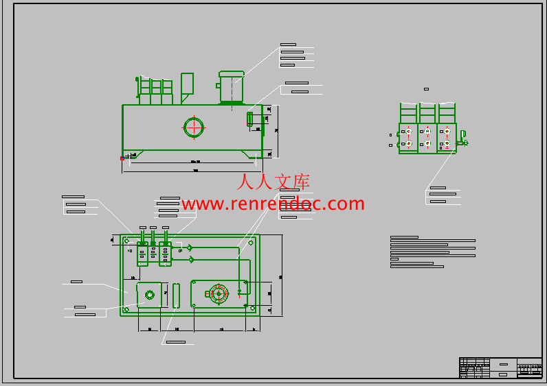
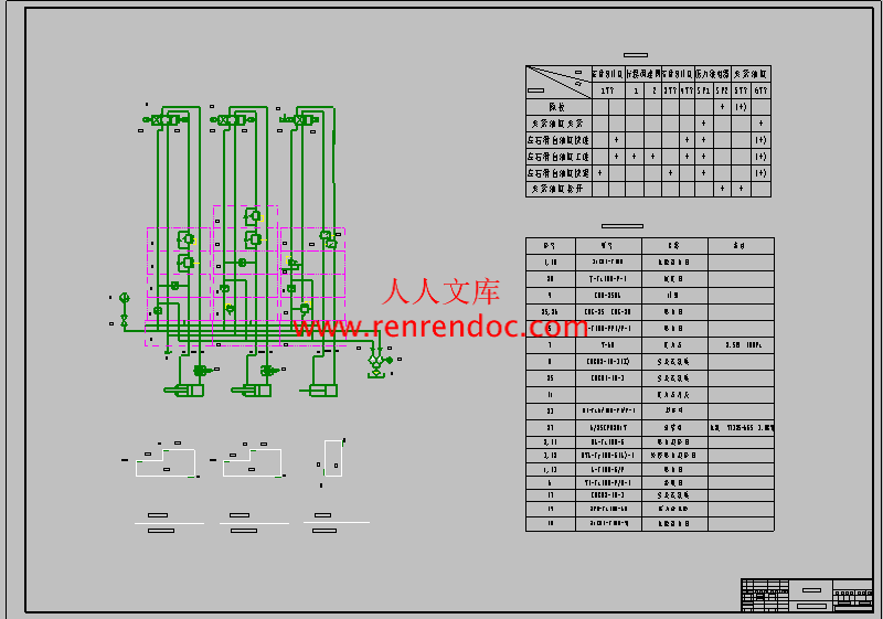
基于AutoCAD轴销两端孔组合钻床液压传动系统设计
23页 6600字数+说明书+开题报告+任务书+文献综述+3张KM图纸
中期检查.doc
任务书.doc
基于AutoCAD轴销两端孔组合钻床液压传动系统设计开题报告.doc
基于AutoCAD轴销两端孔组合钻床液压传动系统设计说明书.doc
外文翻译.doc
封面.doc
撰写规范.doc
文献综述.doc
液压任务书.kmg
诚信承诺书.doc
0000-5101#2.kmg
0000-5102#1.kmg
0000-5141#1.kmg
目 录
1.前言1
2.方案的确定2
2.1整体性分析2
2.2任务书2
2.3确定方案3
3.工况分析3
3.1运动参数分析3
3.2动力参数分析3
3.3负载图和速度图的绘制4
4.液压缸尺寸和所需流量5
4.1液压缸尺寸计算5
4.1.1工作压力的确定5
4.1.2计算液压缸尺寸5
4.1.3缸径、杆径取标准值后的有效工作面积5
4.2确定液压缸所需流量6
4.3夹紧缸的有效面积、工作压力和流量确定6
4.3.1确定夹紧缸的工作压力6
4.3.2计算夹紧缸的流量6
5.拟定液压系统图7
5.1确定执行元件类型8
5.1.1工作缸8
5.1.2夹紧缸8
5.2快速运动的实现和供油部分的设计8
5.3液压系统回路的确定8
6.选择液压元件和确定辅助装置9
6.1选择液压泵9
6.2电动机的选择9
6.3选择阀类元件9
6.4确定油管尺寸10
6.4.1油管内径的确定10
7.油箱的设计11
7.1油箱容量的确定11
7.2估算油箱的长、宽、高11
7.3确定油箱壁厚11
7.4确定液位计的安装尺寸11
7.5隔板的尺寸计算11
8.液压系统性能的验算12
8.1 回路中压力损失12
8.1.1 工进时压力损失12
8.1.2 快退时压力损失13
8.2 确定液压泵工作压力14
8.3 液压系统的效率14
9.结论15
参考文献17
致 谢18
摘 要
目前,液压系统被广泛应用在机械、建筑、航空等领域中,成为一种新型的动力源。由于液压元件的制造精度越来越高,再配合电信号的控制,使液压系统在换向方面可以达到较高的频率。不管是在重型机械和精密设备上都能满足要求。
液压系统本身有较多的优点,比如:在同等的体积下,液压装置产生的动力更大;由于它的质量和惯性小、反映快,使液压装置工作比较平稳;能够实现无级调速,特别是在运动中进行调速;液压装置自身能实现过载保护;实现直线运动远比机械传动简单。但是液压传动对温度的变化比较敏感,不宜在很高或很低的温度下工作。
液压系统应用在机床上,实现对工作台和夹紧工件的循环控制起着重要的作用。本次毕业设计以变速箱壳体专用多轴钻孔机床为研究对象,构建其液压控制回路。实习进给缸的顺序动作及互锁要求。
关键词:液压传动;钻孔机床;运用
要求此液压系统实现的工作循环是:工件夹紧 工作快进 工作台工进 工作台快退 工作台原位停止 工件松开 液压泵卸荷。滑台的重量为132000N,快进快退的速度6米/分,滑台工进速度50 mm/s ,快进行程100mm,工进行程80mm ,切削负载为30000N。
对于轴销两端孔组合钻床机床而言需要精度高,定位准确。所以整个系统的设计要求定位精度高,换向速度快。在设计阀的时候,考虑这些方面变的尤其重要,要考虑到工作在最低速度时调速阀的最小调节流量能否满足要求。在行程方面,应该比要求的工作行程大点,包括工作行程、最大行程和夹紧缸行程,主要是考虑到在安全方面和实际运用中。在压力方面也要考虑到满足最大负载要求。而且在液压系统能满足要求的前提下,使液压系统的成本较低。


- 内容简介:
-
中国地质大学长城学院本科毕业设计外文资料翻译系 别: 工程技术 专 业:机械设计制造及其自动化姓 名: 张学超 学 号: 05208324 2012 年 01 月 18 日外文资料翻译译文组合钻床轴销两端孔液压传动设计一、 研究发展及现状 液压技术渗透到很多领域,不断在民用工业,在机床、工程机械、冶金机械、塑料机械、农林机械,汽车、船舶等行业得到大幅度的应用和发展,而且发展为包括传动、控制和检测在内的一门完整的自动化技术。现今,采用液压传动的程度已经成为衡量一个国家工业水平的重要标志之一。如发达国家生产的95%的工程机械,90%的数控加工中心,95%以上的自动线都采用了液压传动技术。液压传动相对于机械传动来说,是一门新技术。自1795年制成第一台水压机起,液压技术就进入了工程领域,1906年开始应用于国防战备武器。第二次世界大战期间,由于军事工业迫切需要反应快和精度高的自动控制系统,因而出现了液压伺服系统。20世纪60年代以后,由于原子能,空间技术,大型船舰一级计算机技术的发展,不断地对液压技术提出新的要求,液压技术也相应得到了很大发展,渗透到国民经济的各个领域中。在工程机械,冶金,军工,农机,汽车,轻纺,船舶,石油,航空和机床工业中,液压技术得到普遍应用。近年来液压技术已广泛应用于智能机器人,海洋开发,宇宙航行,地震预测及各种电液伺服系统,使液压技术的应用提高到一个崭新的高度。解放前,我国经济落后,液压工业完全是空白,解放后,我国经济获得迅速发展,液压工业也和其他工业一样,发展很快。20世纪50年代就开始生产各种通用液压元件。当前我国已生产出许多新型和自行设计的系列产品。近年来,我国液压气动密封行业坚持技术进步,加快新产品开发,取得良好成效,涌现出一批各具特色的高新技术产品。北京机床所得直动式电液伺服阀,杭州精工液压机电公司的低噪声比例溢流阀,宁波华液公司的电液比例压力流量阀,均为机电一体化的高新技术产品,并已投入大批量生产,取得了良好的经济效益。尽管我国液压行业各企业加速科技创新,不断提升产品市场竞争力,一批优质产品成功地成为国家重点工程和重点主机配套,取得较好的经济效益和社会效益。二、 液压部件工作原理 液压系统是利用液体为介质把能量从动力源传递到消耗位置的动力传递系统。所有液压系统原理都基于帕斯卡定律,是以发现这个定律的帕斯卡的名字而命名的。这个定律表明在一个密封的容器里,如缸体或管子,受压液体向容器表面所有方向施加相等的力。 在实际液压系统中,帕斯卡定律解释从系统中得到的各种结果。泵使流体在系统里流动。泵的吸入口接到液压油容器,通常称为液压油箱。大气压压在油箱里液体上,使液体流入泵里。当液压泵工作时,它以适当的压力把液体从油箱压到管道里。 泵排出的高压液体由阀控制。多数液压系统运用三种控制方式: (1)流体压力控制; (2)流体速度控制; (3)流体方向控制。 在液压系统中由泵排出的液体经由控制阀到液压马达。液压马达利用受压的流体作为它的能量源产生旋转的力和运动。液压马达跟泵的结构类似,只不过它的工作原理是相反的。 在要求直线运动代替旋转运动的地方是用液压缸,它由运动活塞和缸体构成。当活塞由高压流体驱动时,活塞杆传递力,推动负载移动一段设定的距离。 当液压缸中的活塞运动受阻时,例如当活塞有负载,在液压缸中必然会产生一个相应的压力。活塞面积以平方英寸为单位,受压液体的压力乘以活塞面积,就等于在活塞杆的末端产生的一个以磅为单位的输出力。 活塞杆的速度取决于受压液体进入液压缸里的多少。可以控制油液流如液压缸的其中一端,在活塞杆上产生一个拉力或产生一个推力。在活塞上有密封装置,防止流体的泄漏。 活塞的方向控制取决于流体进入液压缸的哪一端,当高压流体进入液压缸的一端时,流体一定从另一端流出。排出的流体又回液压油箱。在利用空气的气动系统里,空气是由缸体排放入大气中的。 方向控制阀也称作二通阀、三通阀和四通阀等等,是根据它们的基本功能命名的。压力控制阀和简单的节流阀,通常采用二通阀,他们仅有通和断功能。三通阀可以有几种功能,这些和三通阀的油口有关。例如,来自泵的高压流体可能传送到拖拉机的液压系统里驱动负载。在不需驱动时,三通阀将高压流体送到驱动输送机构的液压马达上。 也可以用三通阀来控制单作用式液压缸(只能单方面施力)的运动。例如,当三通阀通时,它可以阻止高压流体流入液压缸。同时,该阀可以把液压缸中的液体导向液压油箱,因此,柱塞缸可以在重力或回程弹簧的作用下回到它的初始位置。 四通阀有四个油口。压力油口控制流体连接到需要高压的地方。同时有一个油口从高压区排出油液。排出的液体流回液压油箱。外文原文combination drilling shaft pin hole at both ends of hydraulic drive designresearch present situation and development Hydraulic technology to penetrate to many areas, and constantly in the civilian industry, in machine tools, engineering machinery, metallurgy, machinery, plastic machinery, agricultural, forestry machinery, automobile, shipbuilding industry greatly get the application and development of, and development for including transmission, control and testing, a complete automation technology. Today, the hydraulic transmission levels have become the measure of a country industrial level one of the important marks. Developed countries such as the production of 95% of engineering machinery, 90% of the CNC processing center, more than 95% of the automatic line are adopting hydraulic transmission technology. Hydraulic transmission relative to the mechanical transmission, it is a new technology. Since 1795 the first made hydraulic press on, hydraulic technology into the engineering field, in 1906 began to use of the defense combat readiness weapons. The second world war, because the military industry urgent need of fast response and high precision of the automatic control system, hydraulic servo system appear. After 1960s, because of atomic energy, space technology, large ships level of the development of computer technology, constantly put forward the new requirements of hydraulic technology, hydraulic technology also corresponding have very development, permeate the economy in each field. In engineering machinery, metallurgy, military industry, agricultural machinery, automobile, light textile, ship, oil, aviation and machine tool industry, hydraulic technology used widely. In recent years the hydraulic technology has been widely used in intelligent robot, Marine development and navigating cosmic, earthquake prediction and various kinds of electro-hydraulic servo system, the hydraulic technology application increased to a new height. Before liberation, our country backward economy, hydraulic industry is completely blank, after liberation, Chinas economic rapid development, hydraulic industry and other industries, is developing very quickly. The 1950 s began to produce all kinds of general hydraulic components. The current our country has produced many new and to design a series of products. In recent years, our country hydraulic pneumatic sealing industry to technological progress, speeds up the new product development, has achieved good results, the emergence and a number of distinctive high-tech products.Beijing machine income e-style electric-hydraulic servo valve, hangzhou electrical company of hydraulic seiko low noise proportional relief valve, ningbo China liquid company electrohydraulic proportional pressure flow valve, are all mechanical and electrical integration of high-tech products, and has been put into mass production, achieved good economic benefit. Although our country hydraulic industry each enterprise acceleration science and technology innovation, continuously improve product market competitiveness, a batch of high quality products successfully become national key project and key host kit, get better economic benefits and social benefit.Second, hydraulic components work principle hydraulic system is using liquid medium for the energy from the power consumption of the relay to the position of power transfer system. All hydraulic principle are based on PASCALs law, the law of PASCAL is found that the name and names. This law showed that in a sealed container, such as block or tube, under pressure to tank surface all direction liquid on equal power. In the practical hydraulic system, PASCAL explained by the law of from the system of all kinds of results to get. Pump that fluid flow in the system. The pump suction received the hydraulic oil container, usually called the hydraulic oil tank. Atmospheric pressure in the tank liquid pressure, the liquid into the pump. When the hydraulic pump work, it with the proper pressure from the liquid tank pressure to the pipeline. Because of the high pressure pump fluid from valve control. Most of the hydraulic system using three kinds of control ways:(1) fluid pressure control;(2) fluid speed control; (3) the direction of flow control. In the hydraulic system by the pump in the expulsion of liquid through control valves to hydraulic motor. Hydraulic motor using pressurized fluid as its energy source generates rotating force and motion. Hydraulic motor pump with a structure similar to, but it is the opposite of the working principle. In the requirements linear motion is the place where instead of the rotary motion with the hydraulic cylinder piston and cylinder by the moving it formed. As the piston driven by high pressure fluid, piston rod heritability, promote load a set of mobile distance. When the hydraulic cylinder piston movement of obstruction, for example when the pistons have load, in hydraulic cylinder must be produced a corresponding pressure. The piston area to square inches for the unit, the pressure of the pressure liquid multiplied by the piston area is in the end of the piston rod produced a pound for the unit output force. The speed of the piston rod pressure liquid into the hydraulic cylinder depends on how much the. Can control the oil flow as the hydraulic cylinder at one end, in the piston rod produce a tension or produce a push. On the piston has sealing devices, prevent fluid leakage. The piston direction control depends on fluid into the hydraulic cylinder of which end, when high pressure fluid into the one end of the hydraulic cylinder, fluid from the other end must flow out. The expulsion of fluid and back to the hydraulic oil tank. In the use of air in the pneumatic system, air cylinder is released into the atmosphere by the. Direction control valves are also known as the second valve, the 3-way valve (pos four-way valve and etc, it is according to the basic function of their names. Pressure control valves and simple throttle valve, usually by two valve, they only links, and broken function. Three-way valve can have several function, these and the 3-way valve (pos oil on the mouth. Fo
- 温馨提示:
1: 本站所有资源如无特殊说明,都需要本地电脑安装OFFICE2007和PDF阅读器。图纸软件为CAD,CAXA,PROE,UG,SolidWorks等.压缩文件请下载最新的WinRAR软件解压。
2: 本站的文档不包含任何第三方提供的附件图纸等,如果需要附件,请联系上传者。文件的所有权益归上传用户所有。
3.本站RAR压缩包中若带图纸,网页内容里面会有图纸预览,若没有图纸预览就没有图纸。
4. 未经权益所有人同意不得将文件中的内容挪作商业或盈利用途。
5. 人人文库网仅提供信息存储空间,仅对用户上传内容的表现方式做保护处理,对用户上传分享的文档内容本身不做任何修改或编辑,并不能对任何下载内容负责。
6. 下载文件中如有侵权或不适当内容,请与我们联系,我们立即纠正。
7. 本站不保证下载资源的准确性、安全性和完整性, 同时也不承担用户因使用这些下载资源对自己和他人造成任何形式的伤害或损失。

人人文库网所有资源均是用户自行上传分享,仅供网友学习交流,未经上传用户书面授权,请勿作他用。
 川公网安备: 51019002004831号