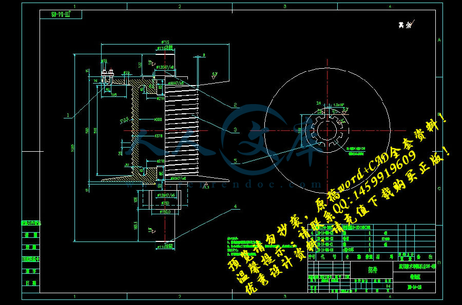
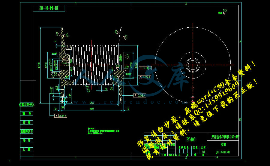
设计说明书绘图过程.dwg
设计说明书绘图过程.dwg

JH14型回柱绞车的设计【矿山辅助设备优秀机械毕业设计@word+11张图纸CAD全套图纸】

收藏

资源目录
跳过导航链接。
压缩包内文档预览:
预览图
编号:291292    类型:共享资源    大小:7.57MB    格式:RAR    上传时间:2014-06-09 上传人:QQ14****9609 IP属地:陕西
50
积分
关 键 词:
jh14 型回柱 绞车 设计 矿山 辅助 设备 装备 优秀 优良 机械 毕业设计 word 11 十一 图纸 cad 全套
资源描述:

中国矿业大学毕业设计任务书

毕业设计题目:JH—14型回柱绞车


毕业设计专题题目:


毕业设计主要内容和要求:

   设计的主要技术参数为

   最大牵引力:

   最大牵引速度:,最小牵引速度:,

   容绳量:

   此次设计的主要内容是回柱绞车电动机的选择,卷筒的设计、减速器的设计等。此次设计要求回柱绞车能够实现两种速度,可以满足不同条件、环境下的回柱,也可以实现回绳与放绳时速度的合理利用。在减速器的设计时要求采用蜗轮蜗杆传动、滑移双联齿轮传动,以及圆柱齿轮传动。滑移齿轮的传动要求采用拨叉拨动的方式来实现。在设计时还需要尽量考虑加工工艺,考虑材料的选用以及加工成本等因素。

   设计的绞车要求具有防爆能力,设计图纸量折合成A0图纸不少于3张半,设计说明正文不少于70页。另外还要求翻译一篇近三年来发表过的并且与本人设计有关的英文论文或专著,中文译文必内容不少于3000汉字。

摘  要


   目前,矿山广泛使用的JH系列回柱绞车多是由JM慢速绞车演变而来的,具有速度低、结构紧凑、牵引力大等特点。主要应用于煤矿井下采煤工作面回柱放顶之用,同时也可用于上山、下山、平巷等综采工作面设备的搬迁。由于它的高度较低重量又轻,特别适用于薄煤层和急倾斜煤层采煤工作面,以及各种采煤工作面回收沉入底板或被矸石压埋的金属支柱。

   本次设计的JH-14型回柱绞车是在我去年毕业实习时所实践的回柱绞车的基础上,再查阅参考有关资料后结合我的一些想法所设计的。在减速器的设计过程中,主要采用了蜗轮蜗杆传动、双联滑移齿轮传动、圆柱齿轮传动等传动方式,利用拨叉拨动小滑移双联齿轮的方式来实现变速,而且在拨叉的设计中,我采用了手柄摇动转盘的方式来实现拨叉的水平移动。在设计卷筒时,考虑到卷筒设计精度要求不太高,因此将以往的卷筒通轴改为在卷筒两端利用过盈配合及焊接的方式来分别固定轴,避免了材料的浪费。

   本次的设计主要特征就是能实现变速,既能满足不同环境下绞车的使用,也实现绞车在回绳和放绳时可以利用不同的速度达到快速回柱。


关键词:JH-14回柱绞车; 双联齿轮; 变速

ABSTRACT

   At present, JH prop-drawing winch which evolved from JM Slow Speed Winch is widely in mine. This machine with advantage of slow speed, compact structure  and big traction force. The prop-drawing winch is mainly used to prop drawing and caving roof in coal working face, but also can be used to relocate the equipment in fully mechanized coal face,such as uphill, downhill, and level gallery working face. Because of its low height and light weight, The prop-drawing winch is suitable for the thin coal seam and steep coal seam, and recovering the various metal pillar which Sinking into the floor or buried by gangue.

   The JH-14 prop-drawing winch is designed based on my Practice on graduation practice last years and consulting large numbers of information, Which also combines many of my new ideas. The design process in the speed reducer, mainly used in the worm-gear transmission, double-slip gear transmission and column gear transmission etc transmission way. slide the small double-gear with the fork-lever to achieve Speed Change. But also in the fork-lever of the design, I used the handle shake rotary table to achieve the fork-lever horizontal movement. The prop-drawing winch drum in the design, taking into account the design precision need not too high,so I put a drum axis     change into connection of drum and axis with interference fitting and welding in Both ends of the drum, reduced the Materials of axis, to avoid the waste of materials.

   The main features of the design is to achieve speed change, it can satisfy the different working environment, but also to make the prop-drawing winch use different speeds to achieve the rapid return to prop drawing in the back rope and up rope.


Keywords:JH-14 prop-drawing winch;double-slip gear;speed change

目    录


1 绪论……………………………………………………………………………………………1

1.1 引言………………………………………………………………………………………1

1.2 概述………………………………………………………………………………………1

1.2.1 绞车概况……………………………………………………………………………1

1.2.2 回柱绞车概况………………………………………………………………………2

1.3 国内外绞车的发展………………………………………………………………………3

1.4 JH-14型回柱绞车的技术特点……………………………………………………………4

2 总体设计………………………………………………………………………………………4

2.1设计总则…………………………………………………………………………………5

2.2 设计条件…………………………………………………………………………………5

2.3 传动方案的设计…………………………………………………………………………5

2.4电动机的设计选择………………………………………………………………………5

2.4.1电动机输出功率的计算………………………………………………………………5

2.4.2确定电动机的型号……………………………………………………………………6

2.4.3牵引钢丝绳直径的确定及滚筒直径的确定…………………………………………7

2.5滚筒的设计计算…………………………………………………………………………8

2.5.1滚筒直径……………………………………………………………………………8

2.5.2滚筒宽度……………………………………………………………………………8

2.5.3滚筒的外径………………………………………………………………………9

2.5.4验算滚筒的平均速度…………………………………………………………………9

3 减速器设计…………………………………………………………………………………10

3.1 减速器总体设计…………………………………………………………………………10

3.1.1 减速器概述…………………………………………………………………………10

3.1.2 减速器设计…………………………………………………………………………10

3.2 减速器参数确定…………………………………………………………………………10

3.2.1 总传动比及传动比分配……………………………………………………………11

3.2.2 传动装置运动参数的计算…………………………………………………………11

3.3 圆弧蜗轮蜗杆的设计计算………………………………………………………………12

3.3.1 蜗杆传动概述………………………………………………………………………12

3.3.2 蜗杆传动的失效形式………………………………………………………………13

3.3.3 蜗杆传动的材料选定………………………………………………………………13

3.3.4 蜗杆传动的结构……………………………………………………………………14

3.3.5 蜗杆传动的主要参数和几何尺寸计算……………………………………………15

3.3.6 蜗杆传动的润滑……………………………………………………………………18

3.4 滑移齿轮的设计计算……………………………………………………………………18

3.4.1 齿轮传动类型………………………………………………………………………18

3.4.2 滑移齿轮概述………………………………………………………………………20

3.4.3 滑移齿轮传动设计计算及强度校核………………………………………………20

3.5 大小齿轮的设计计算……………………………………………………………………26

3.5.1 齿轮传动概述………………………………………………………………………26

3.5.2 齿轮材料选择………………………………………………………………………27

3.5.3 齿轮传动设计及强度校核…………………………………………………………28

3.6 过桥齿轮的设计计算……………………………………………………………………33

3.7 减速器传动轴的设计与校核……………………………………………………………33

3.7.1 蜗杆轴的设计计算…………………………………………………………………33

3.7.2 蜗轮轴的设计计算…………………………………………………………………39

3.8 键的选择及强度校核……………………………………………………………………45

3.8.1 蜗轮轴小滑移齿轮处………………………………………………………………46

3.8.2 蜗轮轴蜗轮处………………………………………………………………………46

3.8.3 大滑移齿轮轴大滑移齿轮处………………………………………………………47

3.8.4 大滑移齿轮轴小齿轮处……………………………………………………………47

3.8.5 第四轴轴过桥齿轮处………………………………………………………………48

3.9 轴承的选择及强度校核…………………………………………………………………48

3.9.1 蜗杆轴上轴承的选择及强度校核…………………………………………………49

3.9.2 蜗轮轴上轴承的选择及强度校核…………………………………………………52

3.9.3 其它轴上轴承的选择………………………………………………………………55

3.10 减速器中拨叉的设计…………………………………………………………………56

3.11 减速器其他部件的设计………………………………………………………………57

3.11.1 通气器……………………………………………………………………………57

3.11.2 油标………………………………………………………………………………57

3.11.3 减速器箱体的设计………………………………………………………………57

4 卷筒齿轮设计………………………………………………………………………………58

4.1 总体设计…………………………………………………………………………………58

4.2 卷筒轴的设计及校核……………………………………………………………………59

4.3 卷筒轴轴承的选择及校核………………………………………………………………64

4.4 大齿轮处键的选择………………………………………………………………………67

5 回柱绞车其它部件…………………………………………………………………………67

5.1 联轴器……………………………………………………………………………………67

5.2 制动器……………………………………………………………………………………68

5.3 底座………………………………………………………………………………………69

6 回柱绞车的润滑与密封……………………………………………………………………69

7 回柱绞车的安装、操作与维护………………………………………………………………70

7.1 回柱绞车的装配、调整及试运转………………………………………………………70

7.2 回柱绞车的安装、固定与操作…………………………………………………………72

7.2.1 回柱绞车的安装与固定……………………………………………………………72

7.2.2 回柱绞车的操作规程………………………………………………………………73

7.3 绞车的维护、拆卸与修理………………………………………………………………75

参考文献………………………………………………………………………………………76

英文原文………………………………………………………………………………………77

中文译文………………………………………………………………………………………81

致  谢…………………………………………………………………………………………87

1 绪 论

1.1引言

   煤炭是我国的基础能源和重要原料,是当前我国能源的主要组成部分之一,在国民经济中占有重要的战略地位,这就是中国的国情。过去以至未来可预见的几十年内,煤炭仍是我国的重要能源,以煤炭为主的能源结构将难以改变,煤炭工业的地位空前提高。但是目前我国的煤炭工业的发展远不能满足整个国民经济的发展需要。因此必须以更快的速度发展煤炭工业。然而,高速发展煤炭工业的出路在于煤炭工业的机械化。

   矿山机械主要面向能源、交通和原材料基础工业部门服务,主要任务是为煤炭、钢铁、有色金属、化工、建材和核工业等部门的矿山开采和原材料的深加工,以及为铁路、公路、水电等大型工程的施工提供先进、高效的技术装备。矿山机械是机械工业中一个品种繁多、设备结构复杂、需求量大、使用面广的机械行业。矿山机械按其用途大致可分为采掘设备、提升设备、窄轨运输设备、破碎粉磨设备、矿用筛分设备、洗选设备和焙烧设备等7大类,30小类,700多个品种和数千种规格。

   矿山机械在经济建设、科技进步和社会发展中占有十分重要的地位和作用,属于国民经济的支柱行业。矿山机械制造业是国家建立独立工业体系的基础,也是衡量一个国家工业实力的重要标志。根据国家重点支持能源、交通和原材料等基础工业发展的产业政策,矿山机械作为这些基础工业的支柱应优先得到国家的重点支持,以得到进一步发展和提高,为煤炭、金属和非金属矿山的开发提供更多的具有国际先进水平的优质、高效设备,满足国民经济发展对能源和原材料的需要。我国绞车的发展大致分为三个阶段。20世纪50年代主要是仿制设计阶段;60年代,自行设计阶段;70年代以后,我国进入标准化、系列化设计阶段。

1.2概述

1.2.1绞车概况

   绞车又称为卷扬机,是用卷筒缠绕钢丝绳或链条以提升或牵引重物的轻小型起重设备。目前国内最大的船用液压拖缆绞车是350T的由泰兴市依科攀船舶设备有限公司设计的。

   1)绞车的特点和用途:

   绞车具有以下特点:通用性高、结构紧凑、体积小、重量轻、起重大、使用转移方便,被广泛应用于建筑、水利工程、林业、矿山、码头等的物料升降或平拖,还可作现代化电控自动作业线的配套设备。有0.5吨~350吨,分为快速和慢速两种。其中高于20吨的为大吨位绞车,绞车可以单独使用,也可作为起重、筑路和矿井提升等机械中的组成部件,因操作简单、绕绳量大、移置方便而广泛应用。绞车主要技术指标有额定负载、支持负载、绳速、容绳量等。

   2)绞车的分类

   绞车按照动力分为手动、电动、液压三类。从用途上分类可分为建筑用绞车和船用绞车。

   绞车按照功能可以分为:船用绞车、工程绞车、矿用绞车、电缆绞车等。

   按照卷筒形式分为单卷筒和和双卷筒。

   按照卷筒分布形式有分为并列双卷筒和前后双卷筒。

   手动绞车:

   手动绞车的手柄回转的传动机构上装有停止器(棘轮和棘爪),可使重物保持在需要的位置。装配或提升重物用的手动绞车还应设置安全手柄和制动器。手动绞车一般用在起重量小、设施条件较差或无电源的地方。

   电动绞车:

   电动绞车广泛用于工作繁重和所需牵引力较大的场所。单卷筒电动绞车的电动机经减速器带动卷筒,电动机与减速器输入轴之间装有制动器。为适应提升、牵引和回转等作业的需要,还有双卷筒和多卷筒装置的绞车。一般额定载荷低于10T的绞车可以设计成电动绞车。

   液压绞车:

   液压绞车主要是额定载荷较大的绞车,一般情况下10T以上到5000T的绞车设计成液压绞车。其结构主要由液压马达(低速或高速马达)、液压常闭多片式制动器、行星齿轮箱、离合器、卷筒、支撑轴、机架、压绳器(选配)等组成。液压马达具有很高的机械效率,起动扭矩大,并可根据工况要求带不同的配流器,还可根据用户需要设计阀组直接集成于马达配油器上,如带平衡阀、过载阀、高压梭阀、调速换向阀或其他性能的阀组,制动器、行星齿轮箱等直接安装于卷筒内,卷筒、支撑轴、机架根据力学要求设计,整体结构简洁合理并具有足够的强度和刚性。因而该系列绞车在结构上具有紧凑、体积小、重量轻、外形美观等特点,在性能上则具有安全性好、效率高、起动扭矩大、低速稳定性好、噪音小、操作可靠等特点。值得一提的是液压马达高的容积效率和美国SUN公司优质的平衡阀解决了一般绞车都存在的二次下滑和空钩抖动现象,使得该系列液压绞车的提升、下放和制动过程平稳,带离合器的绞车还可实现自由下放。安装于配流盘上的集成阀组则有效地简化了用户的液压系统。由于该系列绞车具备上述优点,使其广泛应用于船舶、铁路、工程机械、石油、地质勘探、冶金等行业,其优良性能得到了用户的认可。

1.2.2回柱绞车概况

   回柱绞车又称慢速绞车,是供煤矿井下采煤工作面回柱放顶之用。由于它的高度较低重量又轻,特别适用于薄煤层和急倾斜煤层采煤工作面,以及各种采煤工作面回收沉入底板或被矸石压埋的金属支柱。随着机械化采煤程度的提高,它越来越多地被广泛用于机械化采煤工作面,作为安装、回收牵引各种设备和备件。

   JH14型回柱绞车是一种有效的矿山辅助设备。该型绞车主要应用于回柱放顶之用,同时也可用于上山、下山、平巷等综采工作面设备的搬迁,比如液压支架、溜槽等。此外,拉紧皮带机机头、运料、调度车辆等工作都可以用这种绞车来完成。在港口、码头、建筑工地、工厂企业,这种回柱绞车也可以发挥作用。可见,回柱绞车在煤炭行业、机械行业,包括部分其他行业都有着不可忽视的地位。参考文献:

[1] 成大先编.机械设计手册.北京:化学工业出版社,2004

[2] 广西大学《实用机械零件手册》编写组. 实用机械零件手册.南宁:广西科学技术出版社,1991

[3] 胡宗武,汪西应,汪春生编.起重机设计与实例.北京:机械工业出版社,2005

[4] 李宜民,王慕龄,宫能平编.理论力学.徐州:中国矿业大学出版社,1996

[5] 刘鸿文编.简明材料力学.北京:高等教育出版社,1997

[6] 甘永立编.几何量公差与检测.上海:上海科学技术出版社,2001

[7] 程志红主编.机械设计.南京:东南大学出版社,2006

[8] 王启广编.现代设计理论.徐州:中国矿业大学出版社,2005

[9] 刘德喜编.采掘机械.北京:煤炭工业出版社,2004

[10] 王洪欣,冯雪君编.机械原理.南京:东南大学出版社,2005

[11] 冯之敬.机械制造工程原理.北京:清华大学出版社,2001

[12] 程志红,唐大放编.机械设计课程上机与设计.南京:东南大学出版社,2006

[13] 李国华 张永忠编.机械故障诊断.北京:化学工学出版社,2009

[14] 王绍定编.矿用小绞车[M].北京:煤炭工业出版社,1981

[15] 白杰平,伍峰,潘英编.机械工程科技英语.徐州:中国矿业大学出版社,2001

[16] 王碧琮编.大型绞车的安装.北京:煤炭工业出版社,1959

[17] 万建民,赵连春.JH-14型回柱绞车的改进设计.煤矿机电.2003,(1):39-40

[18] 孙晓东,魏桂清,孙长江. JM2-14型回柱绞车的结构改进.煤矿机械.1999,(3),36

[19] 朱兴民,杨玉芳.双联齿轮在回柱绞车设计中的应用.河北煤炭.1997,(1):50-51

[20] 李景奇.少齿差行星传动在回柱绞车上的应用.煤矿机械.2001,(1):36

[21] 中国矿业大学机械制图教材编写组.画法几何及机械制图.徐州:中国矿业大学出版社,2002

[22] 吴宗泽编.机械设计师手册.北京:机械工业出版社,2002

[23] 王少怀编.机械设计师手册.北京:电子工业出版社,2006


内容简介:
中文译文虚拟制造的多头ZA蜗杆传动的参数设计和运动分析孙剑萍、汤兆平华东交通大学轨道交通学院,江西省 南昌 330013摘要:阿基米德蜗杆轮齿面通常是用CAD来形成和模拟的。本文分析了多头阿基米德蜗杆的加工特征和形成原则,建立了精确的模型,使设计参数化。并利用Pro/E软件,应用虚拟装配和组件之间的相关性质,模拟现实过程,实际制作蜗轮,建立准确的模型。另外,将生成的蜗轮,蜗杆组装,同时对他们的运动进行模拟和分析。关键词:计算机辅助设计、参数化设计、运动分析、Pro/E、多头ZA蜗杆传动装置1、概述阿基米德蜗杆轮齿面的制作,目前一般是用CAD软件模拟制图来代替真正的蜗轮齿形制造1。但是,绘出复杂而又精确的轮齿是非常困难的,此外,蜗轮蜗杆配合被归类为左旋,右旋,单线程和多头的。这就为简历模型增加了困难。本文主要从阿基米德蜗杆(ZA蜗杆)的加工原理入手,模拟其生产过程,并利用Pro/E中的关系函数,实现准确的ZA蜗杆参数模型。此外,在此基础上也无形中制造出了蜗轮,以及蜗轮、蜗杆的组装以及他们的运动分析。2、建立模型的思维过程为了模仿ZA蜗杆的传动过程,绘制大小和形状同参数化蜗轮滚刀相似的横截面,以阿基米德螺旋线为轨迹,利用Pro/E软件中的“变截面扫描/剪切”功能,在蜗杆毛坯上切一个槽,然后仿效槽,多头蜗轮滚刀就生成了。使线程数和轨迹数充分参数化是制造模型的一个难点。关键点是:第一,要设置控制参数(右旋的参数值是1,左旋值是-1)和线程数,然后用方程建立阿基米德螺旋线,从而改变线程数。第二,仿效蜗杆插槽,它是设计师选择路径的“方向”所必须的,并选择蜗杆坯料的轴线作为参考,建立第一个方向,输入线程数等于蜗杆头数,而且输入螺距等于蜗杆各头之间的间隔。在完成蜗轮滚刀的参数化模型后,然后再在此基础上,通过改变参数来产生蜗杆模型。蜗轮和蜗杆滚刀的不同之处在于蜗轮滚刀是刀片槽,而且他们之间的间隙大于蜗轮半径。蜗轮模式的获得是采用蜗轮滚刀虚拟处理的方式。作者的基本思路是:在虚拟环境中,分别建立蜗轮滚刀和蜗轮毛坯,然后将他们放置于坐标系当中,通过装配几何关系理论,使他们能够互相调整。然后利用布尔减法计算在运动过程中不同位置时的参数,直到蜗轮已制作出整个外表面2。3、建立相关参数从以上的思路可以知道ZA蜗杆传动的参数化设计与运动分析需要建立在诸如蜗轮滚刀部分、蜗杆部分,蜗轮滚刀和蜗杆滚刀之间的部件以及蜗轮和蜗杆之间的装配等方面。为了实现参数化设计,这些部分需要设定基本的尺寸。利用Pro/E提供的参数和关系的功能,按照蜗杆与蜗轮之间的参数关系,设置蜗轮、蜗杆的模数,蜗杆特征数,头数,变位系数等,如表1所示。4、建立准确地ZA蜗轮滚刀参数化模型根据以上所有的思路,首先,设计者需要在蜗杆滚刀毛坯上切一个连续的刀槽,如图1(a)所示,然后以蜗杆滚刀轴线为导向线,如同已经生成的刀槽一样继续切槽,并连续几次,直到达到一定的线程数(蜗杆头数),而且蜗杆螺距等于蜗杆各头之间的间距,如图1(b)所示。采用嵌入在Pro/E2.0中的程序模块,用户可以根据设计示意图编辑程序,设计程序,而且可以驱动它的大小,使其充分和参数化。根据系统的提示,用户导入不同的设计变量,蜗轮滚刀就可以生成满足用户要求的结果,如图2所示。5、建立虚拟加工和装配的基准5.1建立装配基准在Pro/E中,这些部分之间的组成元件和装配式互相关联的。为了实现蜗轮滚刀和蜗轮在装配时的相对运动,设计者必须在组件和装配部件分别建立相应的基准点和基准轴,而且使这些数据参数化,如图3所示。每个组件在这些数据的帮助下组装。如果参数发生变化,蜗轮滚刀和蜗轮将根据给定的传动比相对旋转。一般情况下,蜗轮传动装置两角之间的夹角是90。在装配时,设计者必须建立两个独立的纵横基准轴线和蜗轮滚刀和蜗轮装配基准点,并使这些数据参数化。在装配时,除了前面已加以说明的所必须的参数如模数,齿数外,驱动蜗轮滚刀和蜗轮公转的角度参数也是必须要给出的。该参数设置成“角”,初始值是0。最后,要输入关系如下:$d3=(m*q/2)*cos(jiao) /* x-蜗轮滚刀的定位点坐标;$d4=(m*q/2)*sin(jiao) /* y-蜗轮滚刀的定位点坐标;d5=m*z1*n/2 /* z-蜗轮滚刀的定位点坐标;d2=m*z1*n/2 /* z-蜗杆模拟运动中心定位点的坐标APNT0,即x坐标和y坐标都为0,/ *蜗杆和蜗轮滚刀的定位轴是通过点APNT0和垂直线ASM_FRONT,/ *坐标系统ACS0转换为APNT0;$d7=-m*(q+z2+2*x2)/2 /* 中心定位基准点APNT2的Y坐标在蜗轮模拟毛坯的坐标系统ACS0;d8=m*z1*n/2 /*中心定位基准点APNT2的Y坐标在蜗轮模拟毛坯的坐标系统ACS0;/ *蜗轮的定位轴是通过APNT2对齐和垂直ASM_RIGHT;/ *坐标系统转换为模拟蜗轮的APNT2,以默认坐标系统X轴的正方向为z轴正方向,y轴正方向与默认的坐标系统相同;$d9=m*z2/2*cos(jiao*z1/z2) /*蜗轮定位基准点的X坐标在蜗轮模拟坐标系统中;$d10=m*z2/2*sin(jiao*z1/z2) /*蜗轮定位基准点的Y坐标在蜗轮模拟坐标系统中。5.2建立虚拟加工和组装每部分所需的基准为了建立蜗轮滚刀参考圆的一个基准点,在装配期间,将滚刀轴与在组装部件已经建立好的蜗轮滚刀基准轴对齐,将滚刀参考圆的基准点与在组装部件已经建立好的相应的基准点对齐,因为基准点在组装部件上已经被参数化,因此设计师可以实现围绕基准轴旋转滚刀。利用函数关系是非常有必要的,基准点的输入关系如下:d69=m*q/2 /*x-蜗轮滚刀的定位基准点坐标;d71=m*z1*n/2 /*z-蜗轮滚刀的定位基准点坐标。用同样的方法,建立蜗轮毛坯。为了装配方便,设计师在建立模型时,他必须按照装配关系注意蜗轮毛坯轴的方向以及与坐标系统的距离,并设置必要的组装和模拟日期,输入关系如下:D74=m*(q+x2*2)/2 /* z-蜗轮毛坯的定位基准点坐标。6、虚拟加工和装配当装配各组件时,设计者需要分别校准蜗杆轴,蜗轮毛坯轴,蜗杆参考圆的基准点以及蜗轮毛坯参考圆的基准点同他们相应的轴或者是已经建立好的基准点。由于基准点已经在装配时参数化,设计人员可以实现蜗杆和蜗轮毛坯轮围绕他们各自已经改变参数的校准轴旋转。利用“工具 - 参数”功能,改变角的参数值(间隔角越小,蜗轮切割效果越好),该模型就可以生成。利用“编辑 - 构件运算 - 剪切”功能,切割坯料,然后,在蜗轮部分,设计者需要编辑修改前面已经定义过的ID,并改变其每部分的属性,确保其不随参数值的变化而变化。重复上述所有步骤,直到所有蜗轮槽都用蜗轮滚刀完全、均匀的切割出来。如图4所示。改变蜗杆和蜗轮毛坯的参数,就可以生成不同的蜗轮,如图5所示。7、蜗杆传动的虚拟装配和运动分析7.1虚拟装配和模拟运动更换蜗轮滚刀,以蜗杆作为基准组件,蜗轮和蜗杆利用针连接方式进行组装,当连接组装时,模拟运动相应的校准轴和基准点必须分别选择,如图6所示。元件布置完成后,设计人员可以添加模块的相应驱动器和模拟运动。选择“应用程序 - 机制”,设计师可以输入机构模块;单击“定义伺服电机”,分别建立新的“伺服电机1”和“伺服电机2”按钮。选择“类型”标签,在组装蜗轮和蜗杆时,分别选择已经定义过的校准轴以建立“联合轴”,选择“模拟类型”中的“旋转”,设计者还必须注意伺服电机的两个运动方向,在“配置”选项卡中,需要定义伺服电机1 “规范”选项中的“速度”和“等级”中的“常数”,“A”值为360乘以蜗杆的线程数和蜗轮的齿数。将伺服电机2的“A”值设置为360,以确保他们的运动能满足蜗轮蜗杆的传动比。用户单机“运行分析”按钮,新建“分析定义1”。在对话框的“喜好”选项卡中,设置“开始时间”,“结束时间”,“帧计数”和“帧速率”,预设“结束时间”是蜗轮齿数,其余为默认值。7.2运动模拟分析软件中还有一些在机构模块中可以测量的选项,例如“位移”,“速度”,“加速度”,“连接反应”,“网络负载”等。分析蜗轮和蜗杆之间的相对运动,设计者必须选择他们相应的装配坐标系统;确保坐标系统不随蜗杆传动运转。单击“测量结果的原因分析”按钮,新建措施1到措施4,选择“图形测量分析”,单击“图形测量结果”对话框,测量值可以通过图形和数据输出。它是比较直观和准确的,如图7和图8。在机构模块中,单击“重播以前运行分析”按钮,选择对话框中的“干扰”选项卡,在动态干扰条件下检测每个组件;点击“播放当前结果集” - “捕获.”,电脑就可以可以播放MPEG格式的动画(也可以导成mpg电影格式)。从以上输出的所有运动模拟图可以看出以下三点:(1)蜗轮,蜗杆的Y坐标位移值可以利用改变正弦或余弦的方式来变化,Y坐标的速度值也是如此。当他们运行时,他们具有相同的圆周运动规律。(2)蜗轮Y坐标的位移值范围为-132.5至132.5毫米。蜗杆Y坐标的位移值范围是从-45至45毫米。蜗轮Y坐标的速度值范围是从-47.1238至47.1238毫米/秒,蜗杆Y坐标的速度值范围是从-282.743到282.743毫米/秒,这与他们的理论值完全一致。(3)蜗轮的Y坐标有3个正弦波,而蜗杆的Y坐标有53个正弦波。这与蜗轮蜗杆实际的传动比相同。可以看出,所有来自上述的模拟结果和他们的理论计算值是相同的,也与实际相符。参考资料1陈闽杰,赖贞华,李志明。“阿基米德蜗杆在UG环境中的精确建模”,湖北职业技术学院学报,2006,21(3):152156。2谭欣。“平面二次包络环面蜗杆副数字化造型理论及仿真研究”,武汉:武汉理工大学,2003,6:1722。英文原文The Parameterization Design and Motion Analysis for Multi-start ZA Worm Gearing Based on Virtual ProcessingJianping SUN, Zhaoping TANGSchool of Railway Transportation East China Jiao Tong UniversityNanchang, Jiangxi Province 330013, China AbstractArchimedes worm gear s teeth surfaces are comply and their models were usually built approximately in CAD. This article analyses the processing character and formation principle of the Multi-start ZA worm, builds the accurate model and makes the full parametric design. In environment of Pro/E, applying the entire relevance character between virtual assembly and component, simulating reality processes, the worm gear was produced virtually, and its model was built accurately. Furthermore, the generated worm gear and worm were assembled virtually and their motions were simulated and analysed. Keywords: Computer aided design, Parameterization design, Motion analysis, Pro/E, Multi-start ZA worm gearing 1. IntroductionArchimedes worm gear s teeth surfaces are comply. At present, in the common CAD software, it is general that approximate drawing instead of worm gear s really jugged 1.It is very difficult to draw out its complicated and accurate tooth; in addition to, its match worm is classified for left-handed, right-handed, single-thread and multi-start. Those have increased difficulty to build its model. This paper starts mainly from the processing principle of Archimedes column worm (ZA worm), simulate its produce procedure, and make use of relations function in Pro/E, realize the accurate and parametric model of ZA worm. Furthermore, on the basis, the worm gear was produced virtually, and the generated worm gear and worm were assembled virtually and their motions were and analysed. 2. The train of thought to build model To imitate ZA worm turning process, draw cross section with the size and shape of parameterization worm gear hob s cross section, take Archimedes spiral as trajectory, make use of the “Variable Section Sweep/Cut” function in Pro/E, cut off one slot on the worm blank, then pattern the slot, the multi-start worm gear hob is generated. It is the model difficult points to full parameterize its hands and number of threads. The key point is: firstly, to set up the parameters of hands (right-handed value is 1, the left-handed value is -1) and number of threads, to establish the Archimedes spiral by the way of equation which can change with hands and number of threads. Secondly, while pattern worm slot, it is necessary that designer select the pattern way of “Direction”, and select the worm blank s axis as a reference to establish the first direction, enter the number of threads as number of members in the first direction and enter screw pitch as the spacing pattern members in the first direction.After finished worm gear hob parameterized model, on the basis, the worm model can generate by change parameter. The difference between worm and worm gear hob is that the worm gear hob has blade slot, and its radius is a clearance bigger than that of worm gear. The way which get worm gear model is to adopt the worm gear hob virtual processing. The basic train of thought is: in the virtual environment, to establish separately the worm gear blank and the worm hob, then place respectively them in each coordinate system which accord to the theory geometry assembles relation, make them rotate in each regulation, and do the Boole subtraction operation between them at different engagement position in the motion process, until the worm gear has been produced entire envelope surfaces 2.3. Build the relevance parameter From all above the train of thought, it can be known that ZA worm gearing s parameterization design and motion analyse need to build those files such as the worm gear hob part, the worm part, the assembly between the worm gear hob and worm hob, and the assembly between the worm gear and worm. In order to realize parameterization design, these files need to parameterize their fundamental dimension. Table 1.The parametric table parameter m(modulus)q( worm characteristicnumber) z1(number ofthreads)xuan(hands)n(number of turns)value51831.0 4parameter z2 (worm gear teeth number)hax(addendum factor) cx(bottom clearancefactor) alpha(pressure angle) x2(modification coefficient)value531.0 0.2 20-0.1 Making use of the parameters and relations function which Pro/E provides, according to the parameter relation between ?_ 978-1-4244-5268-2/09/$25.00 2009 IEEE Authorized licensed use limited to: CHINA UNIVERSITY OF MINING AND TECHNOLOGY. Downloaded on May 28,2010 at 05:07:00 UTC from IEEE Xplore. Restrictions apply. the worm and worm gear, parameters need be set up such as worm and worm gear s modulus, worm characteristic number, hands, number of threads, number of turns, as shown in table 1.4. To build the precise and parameterization model for ZA worm gear hob According to all above train of thought, firstly, designer need to cut off one slot on worm gear hob blank, as shown in Fig. 1 (a), then take worm gear hob blank axis as direction, pattern the slot which has generated just a moment ago, and add array relation: taking the number of threads as number of members and taking screw pitch as the spacing pattern members, as shown in Fig. 1 (b). (a)(b)Figure 1.Worm hob with a slot (a) and after pattern (b) (m=5, q=18, n=4, z1=3, left-handed) Adopting the Program module which is embedded in Pro/E Wildfire 2.0, the consumer can edit program according to design intention, design program, and can drive it size-fully and parametrically. According to systematic hint, consumer import the different design variable, the worm gear hob can be generated to satisfy consumer s demand, as shown in Fig. 2. Figure 2.The worm hob which parameter has changed (m=2.5, q=11.2, n=6, z1=2, right-handed) 5. Establish the datum of virtual processing and assembly5.1 Establish the datum in assembly fileIn Pro/E, those files are entire relevance between component and assembly. In order to realize the relative motion between worm gear hob and worm gear in the assembly, designer must establish separately the corresponding datum point and datum axis in component and assembly files, and parameterize these data, as shown in Fig. 3. Every component can be assembled with the help of these data. If parameters are changed, the worm gear hob and worm gear will rotate relatively according to given transmission ratio. Figure 3.The needed datum in virtual assembly The included angle is generally 90 degrees between two shafts of worm gearing s component in space. In assembly, designer must establish separately the two necessary datum axes which crisscrossed mutually and datum points for place the worm gear hob and worm gear to assembly, and parameterize these data. In assembly, besides necessary parameters which have be stated before such as modulus, tooth number, the revolution angle parameter is also necessary to drive worm gear hob and worm gear revolution. The parameter is set up as jiao, initial value is 0. Finally it is necessary to input relations as follows: $d3=(m*q/2)*cos(jiao) /* x-coordinate of alignment point for worm gear hob $d4=(m*q/2)*sin(jiao) /* y-coordinate of alignment point for worm gear hob d5=m*pi*z1*n/2 /* z-coordinate of alignment point for worm gear hob d2=m*pi*z1*n/2 /*z-coordinate of alignment central point APNT0 for worm motion simulation, both x-coordinate and y-coordinate are 0 /*the worm and worm gear hob s alignment axis is through point APNT0 and vertical to ASM_FRONT /* the coordinate system ACS0 translates to APNT0 $d7=-m*(q+z2+2*x2)/2 /* the alignment datum central point APNT2 s y-coordinate in the coordinate system ACS0 for the worm gear blank simulation d8=m*pi*z1*n/2 /* the alignment datum central point APNT2 s z-coordinate in the coordinate system ACS0 for the worm gear blank simulation /* the worm gear s alignment axis is through APNT2 and vertical to ASM_RIGHT /*the coordinate system translates to APNT2 for the worm gear simulation, taking the x axis positive direction of default coordinate system as its z axis positive direction, and its y axis ?Authorized licensed use limited to: CHINA UNIVERSITY OF MINING AND TECHNOLOGY. Downloaded on May 28,2010 at 05:07:00 UTC from IEEE Xplore. Restrictions apply. positive direction is the same as that in default coordinate system $d9=m*z2/2*cos(jiao*z1/z2) /*the worm gear alignment datum point s x-coordinate in the worm gear simulation coordinate system $d10=m*z2/2*sin(jiao*z1/z2) /*the worm gear alignment datum point s y-coordinate in the worm gear simulation coordinate system 5.2 Establish the needed datum in each part file for virtual processing and assembly To build a datum point on reference circle of the worm gear hob, align the hob axis with the hob datum axis which has been set up in assembly file while place it to assembly, align the datum point on the hob reference circle with corresponding datum point which has been set up in assembly file, because the datum point has been parameterized in assembly file, so the designer can realize to revolve the hob round their each alignment axis. Then it is necessary to make use of the relations function and input relations for the datum point as follows: d69=m*q/2 /*x-coordinate of alignment datum point for worm gear hob d71=m*pi*z1*n/2 /* z-coordinate of alignment datum point for worm gear hob Using same method, the worm gear blank is built. To be convenient to the after assembly, while the designer build model, he must pay attention to the worm gear blank s axis direction and the distance with coordinate system according to assembly relation, and build the necessary date to assemble and simulate, input relations as follows: D74=m*(q+x2*2)/2 /* z-coordinate of alignment datum point for worm gear blank 6. Virtual processing and assembly While place the components to assemble, designer need to align separately the worm axis, worm gear blank axis, the datum point on the worm s reference circle and the datum point on the worm gear blank s reference circle with their corresponding axis or datum point which have been set up in assembly file. Because the datum points have been parameterized in assembly file, the designer can realize to revolve the worm and the worm gear blank round their each alignment axis by change the parameter. Making use of the “Tools-Parameters” function, changing the value of parameter “jiao” (the interval angle is smaller, the effect of worm gear is cut is better), the model can be regenerated. Making use of the “Edit-Component Operations-Cut Out” function, and cut the blank, then, in worm gear part files, designer edit the definition of the cut out id which has got just a moment ago, and change its attribute from subordinate to independent, ensure that the cut couldn t change follow the after change of the parameter value. To repeat all above step, until all worm gear slots are entirely and homogeneously cut off by the worm gear hob, as Fig.4 shows. To change the parameters of the worm and the worm gear blank, the different worm gear can be generated, as Fig.5 shows. Figure 4.The virtual processing and finished worm gear (m=5, q=18, n=4, z1=3, z2=53, left-handed) Figure 5.To assemble the worm gear with hob (m=5, q=18, n=4, z1=3, z2=53, left-handed) 7. Virtual assembly simulation and motion analysis of worm gearing 7. 1 Virtual assembly and motion simulation Replacing the worm gear hob, taking the worm as a component to place, worm gear is assembled with worm in the pin connection way. When the pin connections assemble, the simulated motion corresponding alignment axis and datum point must be chosen respectively, as Fig.6 shows. Figure 6.Define assemble connection After finished the component placement, the designer can add corresponding drive for them by the mechanism module, and simulate the motion. To choose “Applications-mechanism”, the designer can enter the mechanism module; click the button of “Define Servo Motors”, new built respectively “ServoMotor1” and “ServoMotor2”. In the “Type” label, to set up“Joint Axis” by choose respectively alignment axis which have defined when ?Authorized licensed use limited to: CHINA UNIVERSITY OF MINING AND TECHNOLOGY. Downloaded on May 28,2010 at 05:07:00 UTC from IEEE Xplore. Restrictions apply. assemble the worm gear with the worm, “Motion Type” is to “Rotation”, the designer need to pay attention to motion direction of the two electric motors. In “profile option card, the ServoMotor1 s “Specification” need to be defined as “Velocity”, the “Magnitude” as the “Constant”, and its “A” as 360 multiply with worm s threads number and divide worm gear s teeth number. Hover ServoMotor2 s “A” is set up as 360, to ensure that the engaging movement can satisfy the transmission ratio need between the worm gear and worm. The designer clicks the button of “Run an Analysis”, new built “AnalysisDefinition1”. In dialog box s “preferences” option card, to set up “Start time”, “End time”, “Frame count” and “Frame rate”, expect that “End time” is the worm gear teeth number, the others are default. 7.2 Analyse the motion simulationThere are some types that may be measured in mechanism module, such as “Position”, “Velocity”, “Acceleration”, “Connect Reaction”, “Net Load” etc. Analysing relative motion between the worm gear and the worm, designer must chose their each corresponding assembly coordinate system; ensure that coordinate system can not revolve following worm drive. To click the button of “Generate measure result of analyses”, new built measures from Measure1 to Measure4, and choose the “Graph measurement separately”, click the button of “Graph selected measures for results sets” in dialog box, measure values can be exported by the graph and the data. It is perceptual intuition and accurate, as Fig.7 and Fig.8 shows.Figure 7.Posi
温馨提示:
1: 本站所有资源如无特殊说明,都需要本地电脑安装OFFICE2007和PDF阅读器。图纸软件为CAD,CAXA,PROE,UG,SolidWorks等.压缩文件请下载最新的WinRAR软件解压。
2: 本站的文档不包含任何第三方提供的附件图纸等,如果需要附件,请联系上传者。文件的所有权益归上传用户所有。
3.本站RAR压缩包中若带图纸,网页内容里面会有图纸预览,若没有图纸预览就没有图纸。
4. 未经权益所有人同意不得将文件中的内容挪作商业或盈利用途。
5. 人人文库网仅提供信息存储空间,仅对用户上传内容的表现方式做保护处理,对用户上传分享的文档内容本身不做任何修改或编辑,并不能对任何下载内容负责。
6. 下载文件中如有侵权或不适当内容,请与我们联系,我们立即纠正。
7. 本站不保证下载资源的准确性、安全性和完整性, 同时也不承担用户因使用这些下载资源对自己和他人造成任何形式的伤害或损失。
提示  人人文库网所有资源均是用户自行上传分享,仅供网友学习交流,未经上传用户书面授权,请勿作他用。
关于本文
本文标题:JH14型回柱绞车的设计【矿山辅助设备优秀机械毕业设计@word+11张图纸CAD全套图纸】
链接地址:https://www.renrendoc.com/p-291292.html

官方联系方式

2:不支持迅雷下载,请使用浏览器下载   
3:不支持QQ浏览器下载,请用其他浏览器   
4:下载后的文档和图纸-无水印   
5:文档经过压缩,下载后原文更清晰   
关于我们 - 网站声明 - 网站地图 - 资源地图 - 友情链接 - 网站客服 - 联系我们

网站客服QQ:2881952447     

copyright@ 2020-2025  renrendoc.com 人人文库版权所有   联系电话:400-852-1180

备案号:蜀ICP备2022000484号-2       经营许可证: 川B2-20220663       公网安备川公网安备: 51019002004831号

本站为文档C2C交易模式,即用户上传的文档直接被用户下载,本站只是中间服务平台,本站所有文档下载所得的收益归上传人(含作者)所有。人人文库网仅提供信息存储空间,仅对用户上传内容的表现方式做保护处理,对上载内容本身不做任何修改或编辑。若文档所含内容侵犯了您的版权或隐私,请立即通知人人文库网,我们立即给予删除!