外文翻译.doc

家用洗碗机的设计 【优秀】【word+9张CAD图纸全套】【食品机械】【毕设】

收藏

压缩包内文档预览:
预览图 预览图 预览图 预览图 预览图 预览图
编号:295081    类型:共享资源    大小:574.12KB    格式:RAR    上传时间:2014-07-06 上传人:QQ14****9609 IP属地:陕西
150
积分
关 键 词:
家用 洗碗机 食品机械
资源描述:

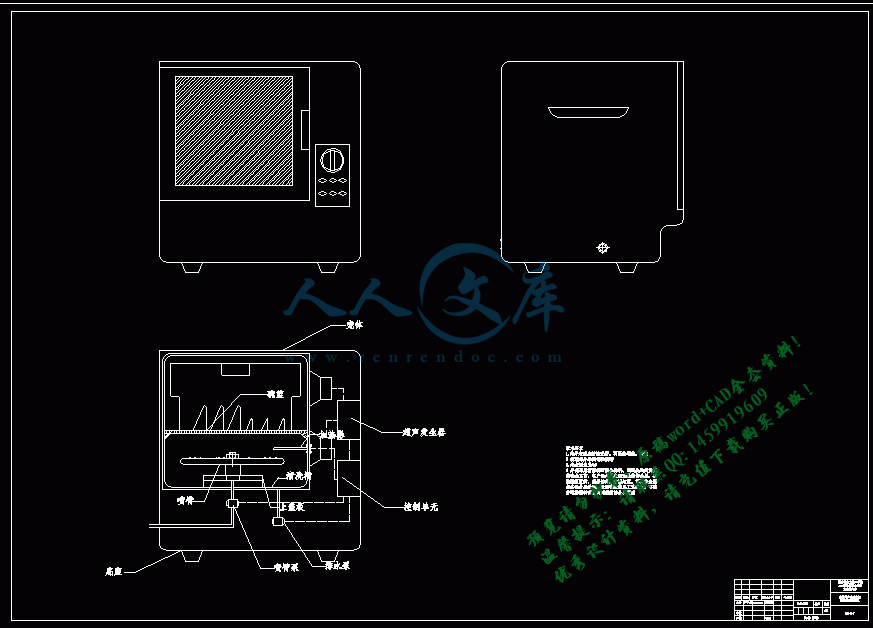
家用超声波洗碗机整体结构设计

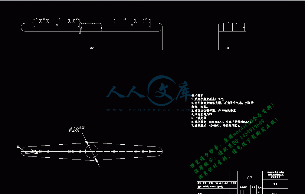
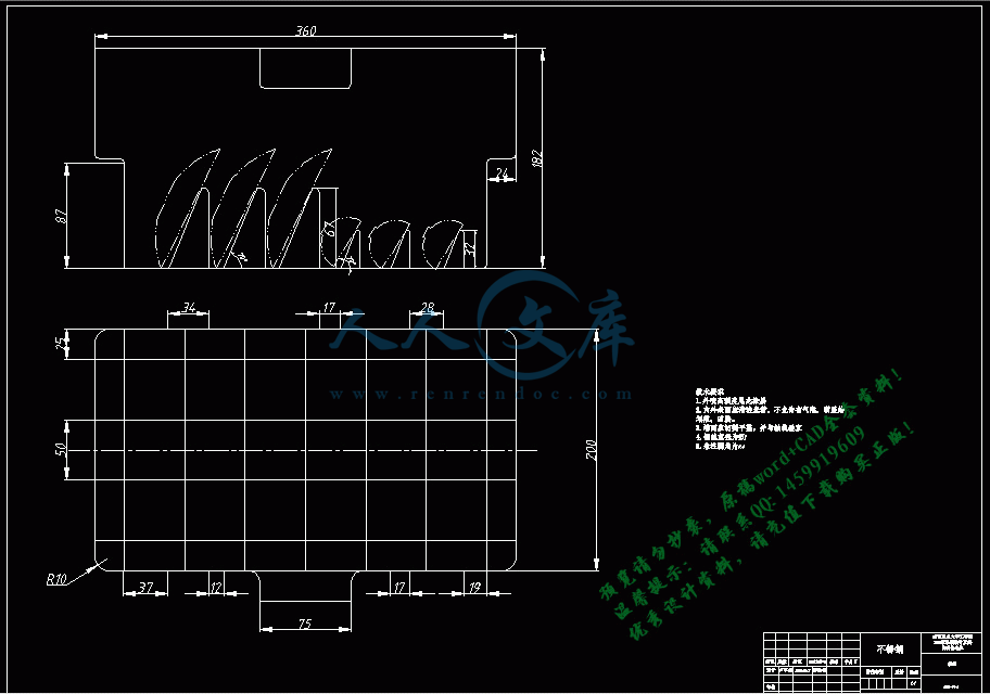
家用洗碗机的设计 【优秀机械毕业设计】【word+9张CAD图纸全套】【带任务书+开题报告+开题论证+中期检查表+选题审批表+外文翻译+】【21页@正文14000字】【详情如下】.bat

中期检查表.doc

任务书.doc

开题报告.doc

开题论证.doc

总汇9张.dwg

正文.docx

选题审批表.doc

目    录  

  摘要1

  1前言1

  1.1家用洗碗机简介1

  1.2国外发展现状2

  1.3 国内发展现状 3

  1.4 国内主流产品3

  2超声波清洗原理及方案4

  2.1超声波清洗原理4

  2.1.1概述4

  2.1.2超声波清洗的机制4

  2.1.3超声空化阀值6

  2.2超声波洗碗机方案设计6

  3超声波清洗参数7

  3.1声强7

  3.2频率8

  3.3清洗液8

  4超声场相对空化强度8

  4.1空化强度测量方法原理8

4.2空化强度测量8

4.2.1实验结果处理9

4.2.2实验结论9

  5超声波重要参数确定10

  5.1温度,清洁时间,超声功率10

  5.2餐具合理摆放11

  5.3总结11

  6洗碗机整体结构设计12

  6.1整体方案12

  6.2外壳和碗篮12

  6.3清洗槽13

  6.4进排水系统13

  6.4.1水位感应系统13

  6.5加热系统14

  6.6门开关电路14

  6.7喷臂系统14

  6.8超声清洗系统15

  6.8.1超声波发生器15

  6.8.2超声波换能器16

  6.9总结17

  7结论17

参考文献18

致谢19

家用超声波洗碗机整体结构设计  

摘  要:超声波技术在洗碗机领域的应用,使洗碗机的发展更加多元。在洗碗机整体结构、清洗工艺和控制系统三个方面进行改良设计。结构方面,采用不锈钢清洗槽,合理布置超声波系统,喷臂冲水装置和进排水装置等,使结构更加紧凑合理,提升清洗效果。清洗工艺方面,分析洗涤槽内超声波空化强度的分布,选择合适的参数,确定最优的清洗流程。            

关键词:超声波;洗碗机;结构设计;          

The structural design of home ultrasonic dishwasher

Student: Lu Yuxiang

Tutor:  Mo Yawu

(College of Engineering, Hunan Agricultural University, Changsha 410128, China)

Abstract: The using of ultrasonic technology make the development of dishwasher more diversified. This paper has improved and redesigned the overall structure of the dishwasher, the cleaning process and control system. The structure: the cleaning tank is made ??of stainless steel. The dishwasher consists of reasonable layout of the ultrasonic system, the spray arm flush device and the plumbing system, so that the structure is more compact and reasonable, to improve the cleaning effect. Cleaning process: figuring out the distribution of ultrasonic cavitations’ intensity and selecting appropriate parameters to determine the optimal cleaning process.

Key words: ultrasonic; dishwasher; the design of overall structure ;                      

1  前言  

1.1家用洗碗机简介

  洗碗机是用来自动清洗碗、筷、盘、碟、刀、叉等餐具的设备,在饭后清洁沾满油污的餐具是人们日常生活中不得不面对的一大家务劳动,洗碗机的出现减轻了劳动强度,提高了工作效率,并增进清洁卫生。

  早在1850年,Joel Houghton就申请到了世界上第一个洗碗机专利,不过是一个手动设备;1893年世界博览会上,蒸汽船发明人John Fitch的孙女Josephine展出了她设计的手动洗碗机,她也被称为现代洗碗机之母;1920年德国米勒公司制造出世界上第一台电动洗碗机,只不过它当时的外形并不适合家庭使用;1954年美国通用电气公司制造出一台电动洗碗机,这台机器不仅洗涤性能大幅改善,而且外形更适合家庭使用;1978年德国米勒公司有制造出第一台微电脑电动洗碗机,使洗碗机开始进入寻常人家的厨房。

现有的家用洗碗机种类繁多,按控制方式分为机电式控制和电子式控制;按安装方式分为台式、独立式和嵌入式;按洗涤方式分为喷淋式和涡流式。虽然市场上有各式各样的洗碗机,但这些洗碗机基本都有机壳、机门、内胆、控制系统、清洗系统和餐具摆放架等重要部件。

机壳有金属和塑料两种。金属机壳的好处是高档,机械强度高,结构牢固,但它也具有易锈蚀,成本高等缺点;塑料机壳的优点是制作成本低,重量轻,但它有易老化,耐热性差等缺点[1]。

机门通常使用冷轧钢板制成,有上开门式和前开门式两种。通常设置有意外开门保护装置,在儿童或其他使用者不小心在家用洗碗机工作过程中打开机门,洗碗机会马上停止工作,以保护人身安全。

内胆是洗碗机工作的重要部件,市面上的洗碗机产品分为塑料内胆和金属内胆两种。金属内胆具有耐用,耐高温,抗老化,易清洗等优点,缺点是易腐蚀,造价高;塑料内胆也具有上述大部分优点,且造价低,但是一个显著的缺点就是难清洗,易留异味。

1.2 国外发展现状

 第一台家用洗碗机起源于德国,同时德国的现代家用洗碗机技术在整个欧洲也处于前列,拥有者BOSCH,Miele,SIEMENS等20多家洗碗机制造商,年产量高达3百万台,消费量也高达1.71百万台,拥有率高达42%。美国是目前洗碗机普及率最高的国家,早在1996年就已达54.9%,同时也是洗碗机生产大国,年产量一直保持在300万台以上,著名企业包括GE等。日本的起步比欧美国家晚了大约30年,并在发展过程中遭受坎坷,现在的普及率仍不及欧美大国,著名企业包括日立,松下,三菱,夏普等均有生产。

国外很多家庭都拥有家用洗碗机,且传统的喷臂式洗碗机十分适合国外餐具的清洗,传统洗碗机是通过电机驱动洗涤泵使洗涤液在一定的压力下从喷臂喷出,形成密集的热水流;喷臂由于受到喷水的反作用而旋转,使洗涤液来回地喷射到各式餐具上,对餐具进行喷射冲洗和淋刷。喷射水流对碗碟表面起机械冲洗作用,洗碗机专用洗涤剂对碗碟表面油污起化学清洗作用,热水起浸泡软化作用。三者联合作用,使碗碟表面油污和残渍分解和脱落,从而达到清洁的目的,且造价低,性价比高,使国外的家用洗碗机的普及率还在不断的增大。良好的市场促进了企业对新型洗碗机的研制和开发,且新型超声波家用洗碗机也开始在国外流行,这种良性循环使国外的洗碗机产业焕发出蓬勃的生机。

1.3 国内发展现状

  我国在80年代有了第一台洗碗机,但是发展过程却不尽如人意。1998年,第一台全自动柜式洗碗机在小天鹅诞生,之后,海尔,美的,澳柯玛,格兰仕等企业纷纷进军洗碗机领域。但是,令人遗憾的是,这些国产企业生产的产品主要外销,作为国产企业,却也没有对国内市场有足够的重视。究其原因,大致有以下几点:一台普通的洗碗机动辄几千元,多则上万元,这对普通消费者来说,是一笔不小的开支,其次是耗电量和耗水量大。一台洗碗机完成洗碗、消毒、烘干耗时长。且洗碗机的功率从600W到2300W不等,消费者将承受更多的电费。国内的洗碗机品牌,如海尔、小天鹅、美的等,最低价格都在2000元左右,加上专用的洗涤剂,不仅价格高,而且不环保;传统的洗碗机需要很大的室内空间,在房价寸土寸金的今天,显然是不经济的;另外,洗碗机工作需要采用专用的洗涤剂,并对餐具的形状有一定要求,不适合中式餐具,且中式菜肴油污较多,洗涤相对麻烦,国内洗碗机多为塑料内胆,长时间使用之后,内胆会变得有异味而且油腻难清洗,出现“洗碗机洗碗,人洗洗碗机”的问题。如此,都决定了传统洗碗机难以在中国快速普及[2] 。

1.4 国内主流产品

  以美的(Midea)举例,目前在商城大致能见到的型号为WQP6-3207-CN,WQP8-9249A-CN,WQP12-9270-CN。三款洗碗机都针对中式餐具配套了碗篮,并配有消毒程序。

  其中,WQP6-3207-CN体积小巧,外观时尚更适合家庭使用。它的洗涤过程为:预洗:对碗具进行强力冲刷,除去残渣;主洗:高温高压水柱,专用洗涤用品作用(2-4个循环,40分钟);漂洗:对餐具进行清洁冲刷(一个循环,14分钟);清洗:最后清洁(一个循环,14分钟);烘干:冷凝式烘干(预热自然烘干)

  WQP12-9270-CN与WQP6-3207-CN相比具有容积更大,可以同时清洗12套餐具的优点,且因其采用360°“水枪式”喷淋系统,且内胆采用圆形转角,使其洗涤效果更高效,基本无死角。

  总的来说,国内洗碗机产品大体可以满足消费者日常需要,洗涤效果基本满意。但基本是传统洗碗机,超声波洗碗机目前仅主要商业使用,例如欧倍力,康洁仕,在家用领域几乎处于空白。

2  超声波清洗原理及方案设计

2.1超声波清洗原理

2.1.1 概述

声波是人耳能感受到的一种纵波,它的频率在16到16000HZ范围内。当频率超过16000HZ超出一般人耳听范围,就称为超声波。超声波和声波一样,可以在气体,液体和固体中传播[3]。

超声波的主要性质有:(1)超声波能传递很强的能量,超声波的作用主要是对其传播方向上的障碍物施加压力(声压)。因此,有时可用这个压力的大小衡量超声波的强度,传播的波动能量越强,则压力也越大。(2)当超声波经过液体介质传播时,将以极高的频率压迫液体介质质点振动,在液体介质中连续地形成压缩和稀疏区域。由于液体基本上是不可压缩的,由此产生压力正,负交变的液压冲击和空化现象。由于这一时间极短,液体空腔和压力可达几十个大气压 ,并且产生巨大的液压冲击。这交变的脉冲压力作用在邻近的零件表面上回使其破坏,引起固体物质分散,破碎等效应。(3)超声波通过不同介质时,在界面上发生波速突变,产生波的反射和折射。反射能量的大小,决定于两种介质的波阻抗(密度与波速的乘积pc称为波阻抗),介质的波阻抗相差愈大,超声波通过界面时的反射率愈高。(4)超声波在一定条件下会产生波的干涉和共振现象。超声加工的应用有:型孔,型腔加工;切割加工;复合加工和超声清洗。目前所用的超声波清洗机中,空化作用和直进流作用应用更多[4]。

2.1.2 超声波清洗的机制:

由于超声波与声波一样是一种疏密的振动波,介质的压力作交替变化。如果对液体中某一确定点进行观察,这点的压力如图曲线A所示。以静压(一般一个大气压)为中心,产生压力的增减,若依次增强超声波的强度,则压力振幅也随着增加,像图曲线B那样,并产生负的压力。

参考文献

[1]. 王向红、毛汉领.超声波洗碗机的设计构想[J] .广西民族学院学报,2003,5(2):33-35.

[2]. 孙嘉燕,李保红,王述洋.洗碗机现状及实现中国洗碗机普及新探索[J].现代科学仪器,2012:137-141.

[3]. 袁易全.近代超声原理与应用[M] .南京:南京大学出版社,1996:55-64.

[4]. 席细平,马重芳等.超声波技术应用现状[J]. 山西化工,2007,27(1)25-29

[5]. 任建新.物理清洗[M].北京:化学工业出版社,2000:322-383.

[6]. 李玉平、周里群.超声波洗碗机技术[J] .家电科技,2004,12(5):155-156.

[7]. 王向红、毛汉领.超声清洗槽内空化强度的测量[J].应用声学,2005,5(3):188-191.

[8]. 徐苏声、陈晏如.家用电动器具原理及设计[M] .北京:中国轻工业出版社:1997

[9]. 李燕.家用型超声波清洗机设计过程中的几个关键点[J]. 机电信息,2009,24:59-60.

[10].周德麟.超声波洗衣机清洗的机理和结构的探讨.家用电器科技,2002(6):72-76

[11].庄开达.家用洗碗机的外观与工业设计[J] .家电科技,2002,10(4):41-42.

[12].刘晋春、赵家齐、赵万声.特种加工[M] .北京:机械工业出版社:2001

[13] Ermeler K, Pfeiffer W , Schoen D , et al. Surge immunity of electronic equipment. IEEE Electrical Insulation Magazine. 2000. 16 (2) : 12~16

[14].徐涛.超声波发生器电源技术的发展(中).洗净技术,2003,12(9):13-17

[15]. 成大先.机械设计手册[M].北京:化学工业出版社,2003:212-224.

[16]. 赵凯华,陈熙谋.电磁学[M].北京:人民教育出版社,1978, 334.


内容简介:
外文原文:Mechanism and MachinesA system that transmits forces in a predetermined manner to accomplish specific objectives may be considered a machine. A mechanism may be defined in a similar manner, but the term mechanism is usually applied to a system where the principal function is to transmit motion. Kinematics is the study of motion in mechanism, while the analysis of force and torques in machined is called dynamics.Once the need for a machine or mechanism with given characteristics is identified, the design process begins. Detailed analysis of displacements, velocities, and accelerations is usually required. This part of the design process is then followed by analysis of force and torques. The design process may continue long after first model have been produce and include redesigns of component that affect velocities, accelerations, force, and torques. In order to successfully compete form year to year, most manufacturers must continuously modify their product and their methods of production. Increases in production rate, upgrading of product performance, redesign for cost and weight reduction, and motion analysis of new product lines are frequently required. Success may hinge on the correct kinematic and dynamic analysis of the problem.Many of the basic linkage configurations have been incorporate into machines designed centuries ago, and the term we use to describe then have change over the year. Thus, definitions and terminology will not be consistent throughout the technical literature. In most cases, however, meanings will be clear form the context of the descriptive matter. A few terms of particular interest to the study of kinematic and dynamics of machines are define below.Link A link is one of the rigid bodies or members joined together to form a kinematic chain. The term rigid link or sometimes simply link is an idealization used in the study of that does not consider small deflections due to strains in machine members. A perfectly rigid or inextensible link can exist only as a textbook type of model of a real machine member. For typical machine part, maximum dimension changes are of only a one-thousandth of the part length. We are justified in neglecting this small motion when considering the much greater motion characteristic of most mechanisms. The word link is used in a general sense to include cams, gears, and other machine members in addition to cranks, connecting rods and other pin-connected components.Degrees-of-freedom The number of degrees-of-freedom of a linkage is the number of independent parameters required to position of every link relative to the frame or fixed link. If the instantaneous configuration of a system may be completely defined by specifying one independent variable, that system has one degree-of-freedom. Most practical mechanisms have one degree-of-freedom.An unconstrained rigid body has six degrees-of-freedom: translation in three coordinates and rotation about three coordinate axes. If the body is restricted to motion in a plane, there are three degrees-of-freedom: translation in two coordinate directions and rotation within the plane.Lower and Higher Pairs Connections between rigid bodies consist of lower and higher pairs of elements. The two elements of a lower pair have theoretical surface contact with one another, while the two elements of a higher pair have theoretical point or line contact (if we disregard deflections).Lower pairs are desirable from a design standpoint since the load at the joint and the resultant wear is spread over the contact surface. Thus, geometric changes or failure due to high contact stresses and excessive wear may be prevented.Mechanism A mechanism is a kinematic chain in which one link is considered fixed for the purpose of analysis, but motion is possible in other links. As noted above, the link designated as the fixed link need not actually be stationary relative to the surface of the earth. A kinematic chain is usually identified as a mechanism if its primary purpose is the modification or transmission of motion.Machine A mechanism designed for the purpose of transmitting forces or torques is usually called a machine.Engine A machine that involves conversion of energy to produce mechanical power is commonly called an engine. Thus, the crankshaft, connecting rod, piston, and cylinder of an automotive engine would be an engine by the above definitions, while other drive train components such as the transmission, differential, and universal joint would be considered machines. Machines and engines may have the same configuration as other mechanisms that do not convert energy and are not intended to transmit significant levels of force or torque. Thus, for the purpose of kinematic analysis, the above distinction between mechanism, machine, and engine may be of only academic importance.A Mechanism has been defined as “a combination of rigid or resistant bodies so formed and connected that they move upon each other with definite relative motion.”Mechanisms form the basic geometrical elements of many mechanical devices including automatic packaging machinery, typewriters, mechanical toys, textile machinery, and others. A mechanism typically is designed to create a desired motion of a rigid body relative to a reference member. Kinematic design of mechanisms is often the first step in the design of a complete machine. When forces are considered, the additional problems of dynamics, bearing loads, stresses, lubrication, and the like are introduced, and the larger problem becomes one of machine design.The function of a mechanism is to transmit or transform motion from one rigid body to another as part of the action of a machine. There are three types of common mechanical devices that can be used as basic elements of a mechanism.Gear Systems Gear systems, in which toothed members in contact transmit motion between rotating shafts. Gears normally are used for the transmission of motion with a constant angular velocity ratio, although noncircular gears can be used for nonuniform transmission of motion.Cam Systems Cam systems, where a uniform motion of an input member is converted into a nonuniform motion of the output member. The output motion may be either shaft rotation, slider translation, or other follower motions created by direct contact between the input cam shape and the follower. The kinematic design of cams involves the analytical or graphical specification of the cam surface shape required to drive the follower with a motion that is a prescribed function of the input motion.Plane and Spatial Linkages They are also useful in creating mechanical motions for a point or rigid body. Linkages can be used for three basic tasks.(1) Rigid body guidance. A rigid body guidance mechanism is used to guide a rigid body through a series of prescribed positions in space.(2) Path generation mechanism will guide a point on a rigid body through a series of points on a specified path in space.(3) Function generation. A mechanism that creates an output motion that is a specified function of the input motion.Mechanisms may be categorized in several different ways to emphasize their similarities and differences. One such grouping divides mechanisms into planar, spherical, and spatial categories. All three groups have many things in common; the criterion which distinguishes the groups, however, is to be found in the characteristics of the motions of the links.A planar mechanism is one in which all particles describe plane curves in space and all these curves lie in parallel planes; i.e. the loci of all points are plane curves parallel to a single common planar mechanism in its true size and shape on a single drawing or figure. The plane four-bar linkage, the plate cam and follower, and the slider-crank mechanism are familiar examples of planar mechanisms. The vast majority of mechanisms in use today are planar.A spherical mechanism is one in which each link has some point which remains stationary as the linkage moves and in which the stationary points of all links lie at a common location; i.e., the locus of each point is a curve contained in a spherical surface, and the spherical surfaces defined by several arbitrarily chosen points are all concentric. The motions of all particles can therefore be completely described by their radial projections, or “shadows,” on the surface of a sphere with properly chosen center. Hookes universal joint is perhaps the most familiar example of a spherical mechanism.Spatial mechanisms, on the other hand, include no restrictions on the relative motions of the particles. The motion transformation is not necessarily coplanar, nor must it be concentric. A spatial mechanism may have particles with loci of double curvature. Any linkage which contains a screw pair, for example, is a spatial mechanism, since the relative motion within a screw pair is helical. 译文:机构与机器一个系统,它按预先确定的方式来传输动力完成的具体的目标也许可以被认为是机器。一种机构也可以以类似的方式定义,但长期的机构通常是适用于一个系统的主要职能是传递运动。运动学是研究机构运动,而分析力和力矩的机械称为动力学。 一旦需要给出识别一个机构或机械装置的特点,设计过程就开始了。通常需要仔细地分析位移,速度和加速度。这部分的设计过程后,其次是分析力和力矩。设计过程中可能会继续很长时间后产生第一种模式,其中包括重新设计的组成部分,影响速度,加速度,力和力矩。年复一年的为了竞争成功,大部分的制造商必须不断地修改他们的产品及其生产方法。提高生产速度,提高产品性能,重新设计的成本和减轻体重,运动分析和新的生产线往往是需要的。成功或许取决于正确的运动学和动力学的分析的问题。许多基本的连接装置构造世纪以前已经成为机器设计的组成部分,和我们使用这个术语形容当时的变化超过一年。因此,定义和专门的术语将不符合整个技术的文献。在大多数情况下,但是,含义将是明确的背景下形成的重要性的描述。有几个方面特别感兴趣的研究机器运动学和动力学的定义如下。 杆件 一个杆件是一个严格的机构或其共同组成一个运动链。长期严格的杆件或有时只是使用一个理想化的杆件研究,由于机件拉紧不考虑微小挠度。一个完全不弯曲或不可拉长的杆件可能存在不仅是一种教科书式的模型,一个真正的机器的构件。对于典型的机械部分,最大尺寸的变化是只有长度部分的千分之一。当我们考虑多数机械装置的运动特性时我们有理由忽视这个小小的运动。这个杆件定理中使用的一般意义上包括凸轮,齿轮,和其他构件除了曲柄、连杆和其他引脚连接组件。自由度 自由度的数量的联系是一些独立的参数必须立场的每一个环节相对内或固定杆件。如果即可改造的系统可以完全确定指定一个独立的变量,该系统有一个自由度。多数实用的机械装置就有一个自由度。 一个无约束刚体有6个自由度:直线移动在三个坐标和旋转运动三个坐标轴。如果该机构是限制于在一个平面运动,那有三个自由度:直线运动在两个坐标方向和在平面内的旋转。 高副和低副 链接的刚体之间包括高副和低副两个要素。这两个因素中的低副是两个理论表面之间的接触,而这两个因素中的高副是理论的点或线接触(如果我们忽视了挠度)。 低副是从设计的角度来看是可取的,由于联合负荷以及由此产生的磨损分布在整个接触面。因此,几何变化或失败而高接触应力和过度磨损或许是可以避免的。机械装置 机械装置是一个运动链系中的一环被认为是特定的目的是为了分析,但运动可能是其他的环节。如上所述,特定的杆件为指定的杆件不需要与实际相对固定在地球表面。如果运动学链主要目的是缓和或传输动力,其就通常被作为一种机械装置, 机器 这种机构设计是为达到转递动力或力矩的目的通常是所谓的机器。 发动机 一个机器需要能量转换而产生的机械动力通常称为发动机。因此,曲轴,连杆,活塞和气缸的自动的发动机由上面所述的发动机的定义,而其他的传动部件,例如变速箱,差速器,和万向联轴器都被称为为机械装置。机器和发动机或许有相同装置,其他的机械装置不能转换动力,而是为了传输大的动力或者是扭矩。因此,为了运动学的分析,上述机械装置、机器、发动机之间的区别,可能仅仅在学术上有重要性。机构就是:由刚体或者是有承载能力的物体连接而组成的组合体,他们在运动时候彼此间具有确定的相互运动。机构是由构成这些机械设备的基本的几何单元,这些机械设备包括自动包装机、打字机、机械的玩具、纺织机等等。机构设计的目的是使一个刚体相对某一个参考的构件产生所需要的相对运动。机构的运动设计通常是设计
温馨提示:
1: 本站所有资源如无特殊说明,都需要本地电脑安装OFFICE2007和PDF阅读器。图纸软件为CAD,CAXA,PROE,UG,SolidWorks等.压缩文件请下载最新的WinRAR软件解压。
2: 本站的文档不包含任何第三方提供的附件图纸等,如果需要附件,请联系上传者。文件的所有权益归上传用户所有。
3.本站RAR压缩包中若带图纸,网页内容里面会有图纸预览,若没有图纸预览就没有图纸。
4. 未经权益所有人同意不得将文件中的内容挪作商业或盈利用途。
5. 人人文库网仅提供信息存储空间,仅对用户上传内容的表现方式做保护处理,对用户上传分享的文档内容本身不做任何修改或编辑,并不能对任何下载内容负责。
6. 下载文件中如有侵权或不适当内容,请与我们联系,我们立即纠正。
7. 本站不保证下载资源的准确性、安全性和完整性, 同时也不承担用户因使用这些下载资源对自己和他人造成任何形式的伤害或损失。
提示  人人文库网所有资源均是用户自行上传分享,仅供网友学习交流,未经上传用户书面授权,请勿作他用。
关于本文
本文标题:家用洗碗机的设计 【优秀】【word+9张CAD图纸全套】【食品机械】【毕设】
链接地址:https://www.renrendoc.com/p-295081.html

官方联系方式

2:不支持迅雷下载,请使用浏览器下载   
3:不支持QQ浏览器下载,请用其他浏览器   
4:下载后的文档和图纸-无水印   
5:文档经过压缩,下载后原文更清晰   
关于我们 - 网站声明 - 网站地图 - 资源地图 - 友情链接 - 网站客服 - 联系我们

网站客服QQ:2881952447     

copyright@ 2020-2025  renrendoc.com 人人文库版权所有   联系电话:400-852-1180

备案号:蜀ICP备2022000484号-2       经营许可证: 川B2-20220663       公网安备川公网安备: 51019002004831号

本站为文档C2C交易模式,即用户上传的文档直接被用户下载,本站只是中间服务平台,本站所有文档下载所得的收益归上传人(含作者)所有。人人文库网仅提供信息存储空间,仅对用户上传内容的表现方式做保护处理,对上载内容本身不做任何修改或编辑。若文档所含内容侵犯了您的版权或隐私,请立即通知人人文库网,我们立即给予删除!